Page History
| Page properties | ||||||||||||||||||||||||||||||||||||||||||||||||||||||||
|---|---|---|---|---|---|---|---|---|---|---|---|---|---|---|---|---|---|---|---|---|---|---|---|---|---|---|---|---|---|---|---|---|---|---|---|---|---|---|---|---|---|---|---|---|---|---|---|---|---|---|---|---|---|---|---|---|
| ||||||||||||||||||||||||||||||||||||||||||||||||||||||||
Design Name is always "TE Series Name" + Design name, for example "TE0720 Test Board"
|
| Custom_table_size_100 |
|---|
| Page properties | ||||||||||||||||||||||||||||||||||||||||
|---|---|---|---|---|---|---|---|---|---|---|---|---|---|---|---|---|---|---|---|---|---|---|---|---|---|---|---|---|---|---|---|---|---|---|---|---|---|---|---|---|
| ||||||||||||||||||||||||||||||||||||||||
Important General Note:
|
Overview
| Scroll Ignore | ||||||||||||||
|---|---|---|---|---|---|---|---|---|---|---|---|---|---|---|
| ||||||||||||||
| Page properties | ||||
|---|---|---|---|---|
| ||||
Notes :
|
MicroBlaze Design with 10 minutes HyperRAM memory test example.
This reference design is bundled with a FREE evaluation edition of the low-cost, commercially proven, high performance memory controller IP supplied by Synaptic Laboratories Ltd (SLL). This free IP evaluation license never expires, and no customer registration or NIC ID is required. Click here to find the latest free trials of SLL’s memory controller IP for HyperBus, OctaBus, Xccela Bus, JEDEC xSPI Profile 1.0 and JEDEC xSPI Profile 2.0 for Intel, Microchip, and Xilinx FPGA. SLL IP is also qualified for use with Trenz HS CRUVI enabled boards. Please send all sales enquiry and technical support questions for SLL’s IP to info@synaptic-labs.com
Refer to http://trenz.org/te0725-info for the current online version of this manual and other available documentation.
| draw.io Diagram | ||||||||||||||||||||
|---|---|---|---|---|---|---|---|---|---|---|---|---|---|---|---|---|---|---|---|---|
|
Key Features
| Page properties | ||||
|---|---|---|---|---|
| ||||
Notes :
|
| Excerpt |
|---|
|
Revision History
| Page properties | ||||
|---|---|---|---|---|
| ||||
Notes :
|
| Scroll Title | ||||||||||||||||||||||||||||||||||||||||||||||||
|---|---|---|---|---|---|---|---|---|---|---|---|---|---|---|---|---|---|---|---|---|---|---|---|---|---|---|---|---|---|---|---|---|---|---|---|---|---|---|---|---|---|---|---|---|---|---|---|---|
| ||||||||||||||||||||||||||||||||||||||||||||||||
|
Release Notes and Know Issues
| Page properties | ||||
|---|---|---|---|---|
| ||||
Notes :
|
| Scroll Title | ||||||||||||||||||||||||||
|---|---|---|---|---|---|---|---|---|---|---|---|---|---|---|---|---|---|---|---|---|---|---|---|---|---|---|
| ||||||||||||||||||||||||||
|
Requirements
Software
| Page properties | ||||
|---|---|---|---|---|
| ||||
Notes :
|
| Scroll Title | ||||||||||||||||||||
|---|---|---|---|---|---|---|---|---|---|---|---|---|---|---|---|---|---|---|---|---|
| ||||||||||||||||||||
|
Hardware
| Page properties | ||||
|---|---|---|---|---|
| ||||
Notes :
|
Basic description of TE Board Part Files is available on TE Board Part Files.
Complete List is available on <design name>/board_files/*_board_files.csv
Design supports following modules:
| Scroll Title | ||||||||||||||||||||||||||||||||||||||||||||||||||||||||||||||||||||||||||
|---|---|---|---|---|---|---|---|---|---|---|---|---|---|---|---|---|---|---|---|---|---|---|---|---|---|---|---|---|---|---|---|---|---|---|---|---|---|---|---|---|---|---|---|---|---|---|---|---|---|---|---|---|---|---|---|---|---|---|---|---|---|---|---|---|---|---|---|---|---|---|---|---|---|---|
| ||||||||||||||||||||||||||||||||||||||||||||||||||||||||||||||||||||||||||
*used as reference |
Design supports following carriers:
| Scroll Title | ||||||||||||||||||||||
|---|---|---|---|---|---|---|---|---|---|---|---|---|---|---|---|---|---|---|---|---|---|---|
| ||||||||||||||||||||||
|
Additional HW Requirements:
| Scroll Title | ||||||||||||||||||||||||
|---|---|---|---|---|---|---|---|---|---|---|---|---|---|---|---|---|---|---|---|---|---|---|---|---|
| ||||||||||||||||||||||||
|
Content
| Page properties | ||||
|---|---|---|---|---|
| ||||
Notes :
|
For general structure and of the reference design, see Project Delivery - AMD devices
Design Sources
| Scroll Title | |||||||||||||||||||||||
|---|---|---|---|---|---|---|---|---|---|---|---|---|---|---|---|---|---|---|---|---|---|---|---|
| |||||||||||||||||||||||
|
Additional Sources
| Scroll Title | ||||||||||||||||||||||||
|---|---|---|---|---|---|---|---|---|---|---|---|---|---|---|---|---|---|---|---|---|---|---|---|---|
| ||||||||||||||||||||||||
|
Prebuilt
| Page properties | |||||||||||||||||||||||||||||||||||||||||||||||||||||||||||||||||||
|---|---|---|---|---|---|---|---|---|---|---|---|---|---|---|---|---|---|---|---|---|---|---|---|---|---|---|---|---|---|---|---|---|---|---|---|---|---|---|---|---|---|---|---|---|---|---|---|---|---|---|---|---|---|---|---|---|---|---|---|---|---|---|---|---|---|---|---|
| |||||||||||||||||||||||||||||||||||||||||||||||||||||||||||||||||||
Notes :
|
| Scroll Title | ||||||||||||||||||||||||||||||||||||||||||||||||
|---|---|---|---|---|---|---|---|---|---|---|---|---|---|---|---|---|---|---|---|---|---|---|---|---|---|---|---|---|---|---|---|---|---|---|---|---|---|---|---|---|---|---|---|---|---|---|---|---|
| ||||||||||||||||||||||||||||||||||||||||||||||||
|
Download
Reference Design is only usable with the specified Vivado/Vitis/PetaLinux version. Do never use different Versions of Xilinx Software for the same Project.
| Page properties | ||||
|---|---|---|---|---|
| ||||
|
Reference Design is available on:
Design Flow
| Scroll Ignore | ||||||||||||||
|---|---|---|---|---|---|---|---|---|---|---|---|---|---|---|
| ||||||||||||||
| Page properties | ||||
|---|---|---|---|---|
| ||||
Notes :
|
| Note |
|---|
Reference Design is available with and without prebuilt files. It's recommended to use TE prebuilt files for first lunch. |
Trenz Electronic provides a tcl based built environment based on Xilinx Design Flow.
See also:
- AMD Development Tools#XilinxSoftware-BasicUserGuides
- Vivado Projects - TE Reference Design
- Project Delivery.
The Trenz Electronic FPGA Reference Designs are TCL-script based project. Command files for execution will be generated with "_create_win_setup.cmd" on Windows OS and "_create_linux_setup.sh" on Linux OS.
TE Scripts are only needed to generate the vivado project, all other additional steps are optional and can also executed by Xilinx Vivado/Vitis GUI. For currently Scripts limitations on Win and Linux OS see: Project Delivery Currently limitations of functionality
| Note |
|---|
Caution! Win OS has a 260 character limit for path lengths which can affect the Vivado tools. To avoid this issue, use Virtual Drive or the shortest possible names and directory locations for the reference design (for example "x:\<project folder>") |
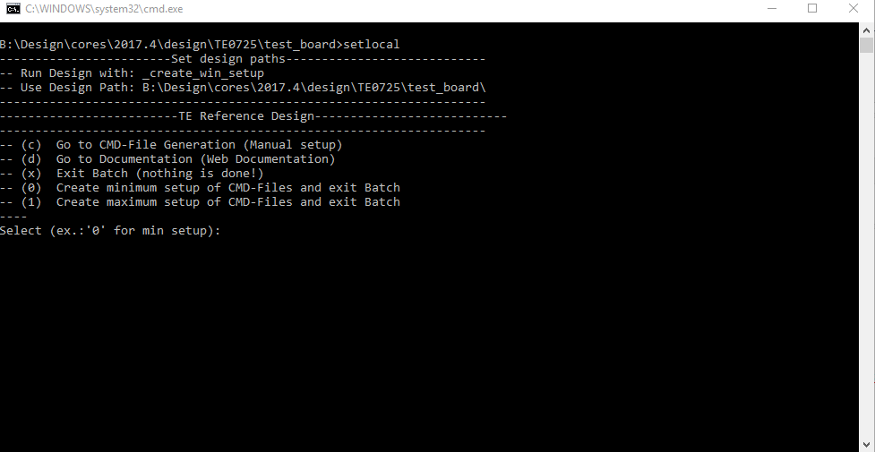
Run _create_win_setup.cmd/_create_linux_setup.sh and follow instructions on shell:
Code Block language bash theme Midnight title _create_win_setup.cmd/_create_linux_setup.sh ------------------------Set design paths---------------------------- -- Run Design with: _create_win_setup -- Use Design Path: <absolute project path> -------------------------------------------------------------------- -------------------------TE Reference Design--------------------------- -------------------------------------------------------------------- -- (0) Module selection guide, project creation...prebuilt export... -- (1) Create minimum setup of CMD-Files and exit Batch -- (2) Create maximum setup of CMD-Files and exit Batch -- (3) (internal only) Dev -- (4) (internal only) Prod -- (c) Go to CMD-File Generation (Manual setup) -- (d) Go to Documentation (Web Documentation) -- (g) Install Board Files from Xilinx Board Store (beta) -- (a) Start design with unsupported Vivado Version (beta) -- (x) Exit Batch (nothing is done!) ---- Select (ex.:'0' for module selection guide):- Press 0 and enter to start "Module Selection Guide"
- Createproject and follow instructions of the product selection guide, settings file will be configured automatically during this process.
optional for manual changes: Select correct device and Xilinx install path on "design_basic_settings.cmd" and create Vivado project with "vivado_create_project_guimode.cmd"
Note Note: Select correct one, see also Vivado Board Part Flow
Create hardware description file (.xsa file) for PetaLinux project and export to prebuilt folder
Code Block language py theme Midnight title run on Vivado TCL (Script generates design and export files into "<project folder>\prebuilt\hardware\<short name>") TE::hw_build_design -export_prebuiltInfo Using Vivado GUI is the same, except file export to prebuilt folder.
Generate Programming Files with Vitis
Code Block language py theme Midnight title run on Vivado TCL (Script generates applications and bootable files, which are defined in "test_board\sw_lib\apps_list.csv") TE::sw_run_vitis -all TE::sw_run_vitis (optional; Start Vitis from Vivado GUI or start with TE Scripts on Vivado TCL)Info Note: Scripts generate applications and bootable files, which are defined in "sw_lib\apps_list.csv"
App from Firmware folder will be add into BlockRAM. If you add other app, you must select *.elf
manually on Vivado
Note TCL scripts generate also platform project, this must be done manually in case GUI is used. See Vitis
(optional) Copy Application (spi_bootloader.elf) from prebuilt-folder into \firmware\microblaze_0\ and regenerate design with
Code Block language py theme Midnight title run on Vivado TCL (Script generates design and export files into "<project folder>\prebuilt\hardware\<short name>") TE::hw_build_design -export_prebuilt
Launch
| Scroll Ignore | ||||||||||||||
|---|---|---|---|---|---|---|---|---|---|---|---|---|---|---|
| ||||||||||||||
Programming
| Page properties | ||||
|---|---|---|---|---|
| ||||
Note:
|
| Note |
|---|
Check Module and Carrier TRMs for proper HW configuration before you try any design. Reference Design is also available with prebuilt files. It's recommended to use TE prebuilt files for first launch. |
Get prebuilt boot binaries
- Run _create_win_setup.cmd/_create_linux_setup.sh and follow instructions on shell
- Press 0 and enter to start "Module Selection Guide"
- Select assembly version
- Validate selection
Select create and open delivery binary folder
Info Note: Folder "<project folder>\_binaries_<Article Name>" with subfolder "boot_<app name>" for different applications will be generated
QSPI
- Connect JTAG and power on carrier with module
Open Vivado Project with "vivado_open_existing_project_guimode.cmd" or if not created, create with "vivado_create_project_guimode.cmd"
Code Block language py theme Midnight title run on Vivado TCL (Script programs .mcs-File on QSPI flash) TE::pr_program_flash -swapp hello_te0725- Press the reset button to start the application and see the output in the console
SD
Not used on this Example.
JTAG
- Connect JTAG and power on PCB
- Open Vivado HW Manager
- Program FPGA with Bitfile from "prebuilt\hardware\<short dir>\"
Usage
| Info |
|---|
HBMC IP is a 10 minute run-time limited evaluation version of the full-edition |
- Prepare HW like described on section Programming
- Connect UART USB (most cases same as JTAG)
Expand title boot process 1. FPGA Loads Bitfile from Flash
3. Hello Trenz will be run on UART console.
info: Do not reboot, if Bitfile programming over JTAG is used as programming method.
UART
Open Serial Console (e.g. putty) Hello TE0725 will run on endless loop.
- Speed: 9600
- COM Port: Win OS, see device manager, Linux OS see dmesg |grep tty (UART is *USB1)
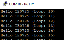
Power On PCB (Do not restart, if you use Bitfile programming)
System Design - Vivado
| Scroll Ignore | ||||||||||||||
|---|---|---|---|---|---|---|---|---|---|---|---|---|---|---|
| ||||||||||||||
| Page properties | ||||
|---|---|---|---|---|
| ||||
Note:
|
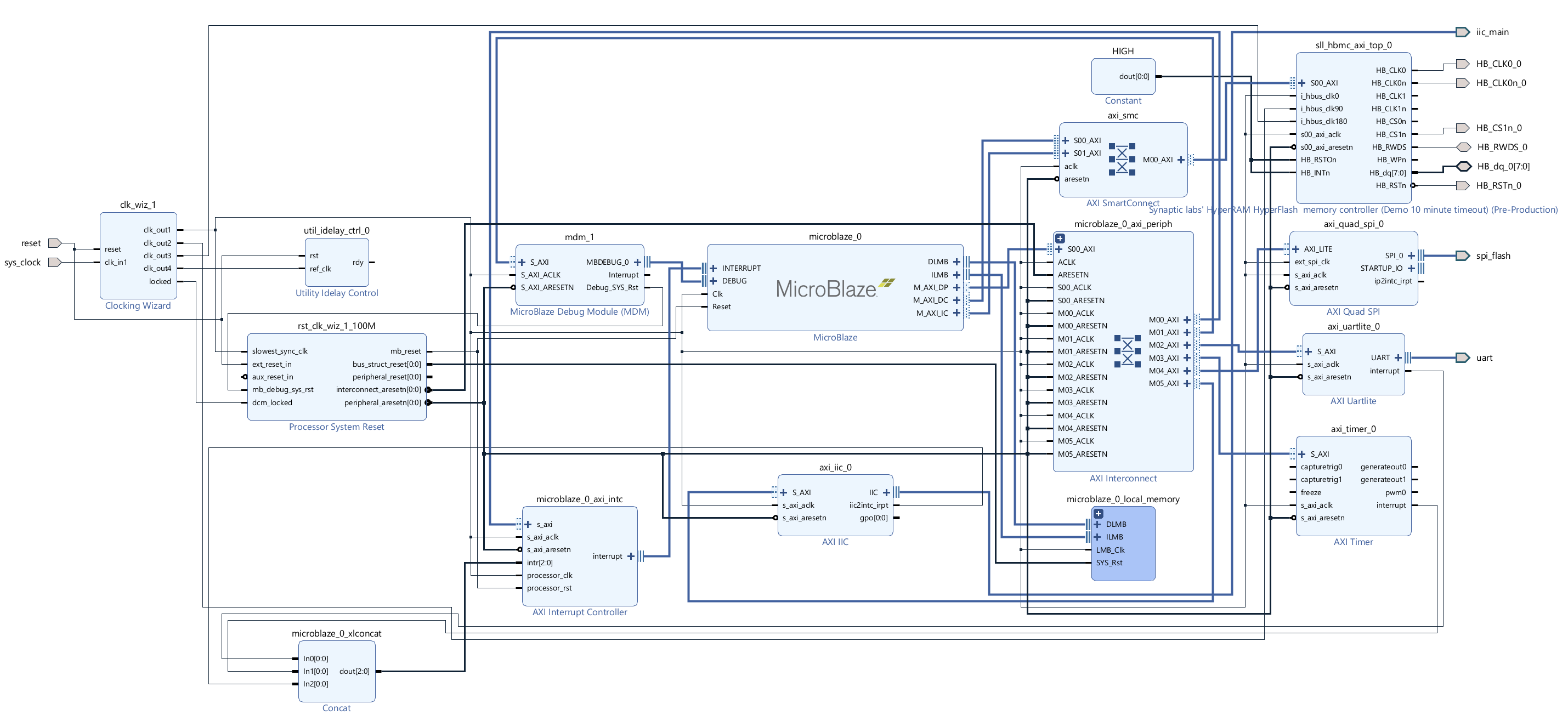
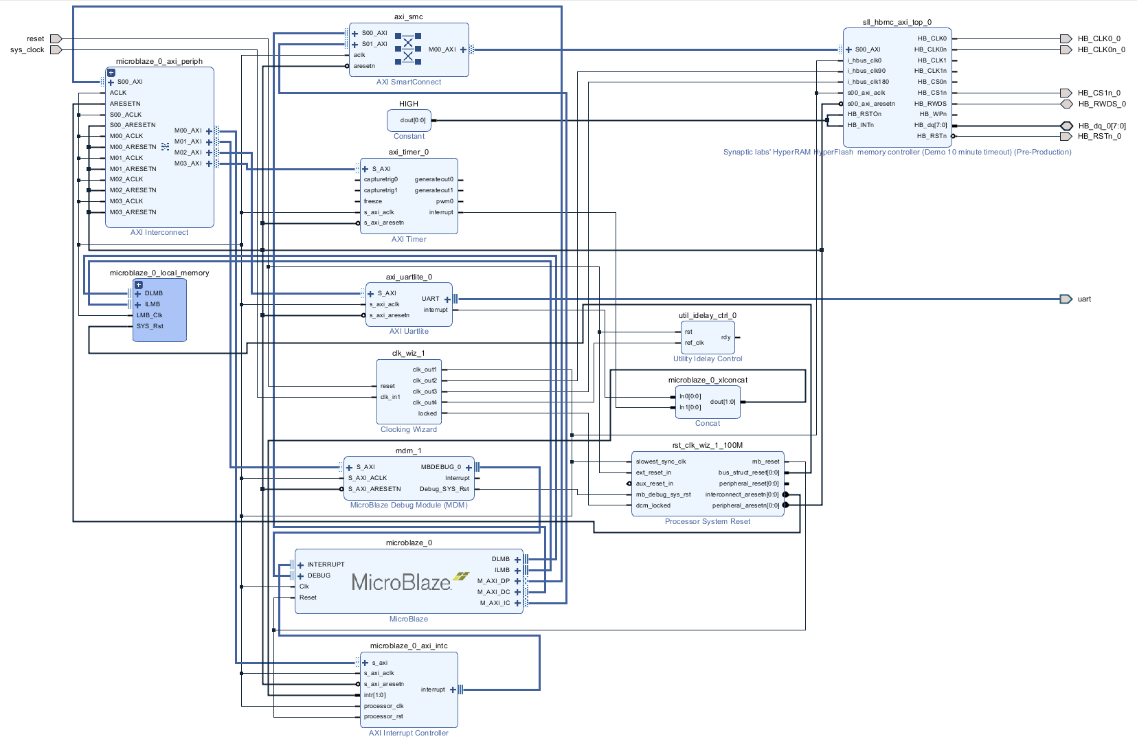
Block Design
Constraints
Basic module constraints
| Code Block | ||||
|---|---|---|---|---|
| ||||
set_property BITSTREAM.GENERAL.COMPRESS TRUE [current_design]
set_property BITSTREAM.CONFIG.CONFIGRATE 50 [current_design]
set_property CONFIG_VOLTAGE 3.3 [current_design]
set_property CFGBVS VCCO [current_design]
set_property BITSTREAM.CONFIG.SPI_32BIT_ADDR YES [current_design]
set_property BITSTREAM.CONFIG.SPI_BUSWIDTH 4 [current_design]
set_property BITSTREAM.CONFIG.M1PIN PULLNONE [current_design]
set_property BITSTREAM.CONFIG.M2PIN PULLNONE [current_design]
set_property BITSTREAM.CONFIG.M0PIN PULLNONE [current_design]

set_property BITSTREAM.CONFIG.USR_ACCESS TIMESTAMP [current_design]
|
Design specific constraints
| Code Block | ||||
|---|---|---|---|---|
| ||||
set_property PACKAGE_PIN A13 [get_ports HB_CLK0_0]
set_property PACKAGE_PIN A14 [get_ports HB_CLK0n_0]

set_property PACKAGE_PIN E17 [get_ports {HB_dq_0[0]}]
set_property PACKAGE_PIN B17 [get_ports {HB_dq_0[1]}]
set_property PACKAGE_PIN F18 [get_ports {HB_dq_0[2]}]
set_property PACKAGE_PIN F16 [get_ports {HB_dq_0[3]}]
set_property PACKAGE_PIN G17 [get_ports {HB_dq_0[4]}]
set_property PACKAGE_PIN D18 [get_ports {HB_dq_0[5]}]
set_property PACKAGE_PIN B18 [get_ports {HB_dq_0[6]}]
set_property PACKAGE_PIN A16 [get_ports {HB_dq_0[7]}]


set_property PACKAGE_PIN E18 [get_ports HB_RWDS_0]

set_property PACKAGE_PIN D17 [get_ports HB_CS1n_0]
set_property PACKAGE_PIN J17 [get_ports HB_RSTn_0]

#set_property PACKAGE_PIN A18 [get_ports HB_CS0n_0 ]
#set_property PACKAGE_PIN J18 [get_ports HB_INTn_0 ]
#set_property PACKAGE_PIN C17 [get_ports HB_RSTOn_0]


#
# FPGA Pin Voltage assignment
#
set_property IOSTANDARD LVCMOS18 [get_ports HB_CLK0_0]
set_property IOSTANDARD LVCMOS18 [get_ports HB_CLK0n_0]
set_property IOSTANDARD LVCMOS18 [get_ports {HB_dq_0[*]}]
set_property IOSTANDARD LVCMOS18 [get_ports HB_CS1n_0]
set_property IOSTANDARD LVCMOS18 [get_ports HB_RSTn_0]
set_property IOSTANDARD LVCMOS18 [get_ports HB_RWDS_0]

#set_property IOSTANDARD LVCMOS18 [get_ports HB_CS0n_0]
#set_property IOSTANDARD LVCMOS18 [get_ports HB_INTn_0]
#set_property IOSTANDARD LVCMOS18 [get_ports HB_RSTOn_0]

#set_property PULLUP true [get_ports HB_RSTOn_0]
#set_property PULLUP true [get_ports HB_INTn_0]

#
#Hyperbus Clock - change according to clk pin on PLL
#
create_generated_clock -name clk_0   -source [get_pins msys_i/clk_wiz_0/inst/mmcm_adv_inst/CLKIN1] -master_clock sys_clock [get_pins msys_i/clk_wiz_0/inst/mmcm_adv_inst/CLKOUT0]
create_generated_clock -name clk_90  -source [get_pins msys_i/clk_wiz_0/inst/mmcm_adv_inst/CLKIN1] -master_clock sys_clock [get_pins msys_i/clk_wiz_0/inst/mmcm_adv_inst/CLKOUT1]
create_generated_clock -name clk_180 -source [get_pins msys_i/clk_wiz_0/inst/mmcm_adv_inst/CLKIN1] -master_clock sys_clock [get_pins msys_i/clk_wiz_0/inst/mmcm_adv_inst/CLKOUT2]

#
#100Mhz clock freqeuncy - change accordingly
#
set hbus_freq_ns   10

set dqs_in_min_dly -0.5
set dqs_in_max_dly  0.5

set HB_dq_ports    [get_ports HB_dq_0[*]]

#
#Create RDS clock and RDS virtual clock
#
create_clock -period $hbus_freq_ns -name rwds_clk      [get_ports HB_RWDS_0]
create_clock -period $hbus_freq_ns -name virt_rwds_clk

#
#Input Delay Constraint -  HB_RWDS-HB_DQ
#
set_input_delay -clock [get_clocks virt_rwds_clk]             -max ${dqs_in_max_dly} ${HB_dq_ports}
set_input_delay -clock [get_clocks virt_rwds_clk] -clock_fall -max ${dqs_in_max_dly} ${HB_dq_ports} -add_delay

set_input_delay -clock [get_clocks virt_rwds_clk]             -min ${dqs_in_min_dly} ${HB_dq_ports} -add_delay
set_input_delay -clock [get_clocks virt_rwds_clk] -clock_fall -min ${dqs_in_min_dly} ${HB_dq_ports} -add_delay

set_multicycle_path -setup -end -rise_from [get_clocks virt_rwds_clk] -rise_to [get_clocks rwds_clk] 0
set_multicycle_path -setup -end -fall_from [get_clocks virt_rwds_clk] -fall_to [get_clocks rwds_clk] 0

set_false_path  -fall_from [get_clocks virt_rwds_clk] -rise_to [get_clocks rwds_clk] -setup
set_false_path  -rise_from [get_clocks virt_rwds_clk] -fall_to [get_clocks rwds_clk] -setup
set_false_path  -fall_from [get_clocks virt_rwds_clk] -fall_to [get_clocks rwds_clk] -hold
set_false_path  -rise_from [get_clocks virt_rwds_clk] -rise_to [get_clocks rwds_clk] -hold

set_false_path -from [get_clocks clk_0] -to [get_clocks rwds_clk]
set_false_path -from [get_clocks rwds_clk] -to [get_clocks clk_0]

#
#Output Delay Constraint -  HB_CLK0-HB_DQ
#

create_generated_clock -name HB_CLK0_0 -source [get_pins */*/*/U_IO/U_CLK0/dq_idx_[0].ODDR_inst/C] -multiply_by 1 -invert [get_ports HB_CLK0_0]

set_output_delay -clock [get_clocks HB_CLK0_0] -min -1.000 ${HB_dq_ports}
set_output_delay -clock [get_clocks HB_CLK0_0] -max  1.000 ${HB_dq_ports}
set_output_delay -clock [get_clocks HB_CLK0_0] -min -1.000 ${HB_dq_ports} -clock_fall -add_delay
set_output_delay -clock [get_clocks HB_CLK0_0] -max  1.000 ${HB_dq_ports} -clock_fall -add_delay


set_false_path -from [get_pins */*/*/U_HBC/*/dq_io_tri_reg/C] -to ${HB_dq_ports}

set_false_path -from * -to [get_pins */*/inst/*/i_iavs0_270_rstn_1_reg/CLR]
set_false_path -from * -to [get_pins */*/inst/*/i_iavs0_270_rstn_2_reg/CLR]
set_false_path -from * -to [get_pins */*/inst/*/i_iavs0_270_rstn_3_reg/CLR]


set_false_path -from [get_clocks rwds_clk] -to [get_clocks -of_objects [get_pins msys_i/clk_wiz_1/inst/mmcm_adv_inst/CLKOUT0]]
set_false_path -from [get_clocks virt_rwds_clk] -to [get_clocks rwds_clk] |
Software Design - Vitis
| Scroll Ignore | ||||||||||||||
|---|---|---|---|---|---|---|---|---|---|---|---|---|---|---|
| ||||||||||||||
| Page properties | ||||
|---|---|---|---|---|
| ||||
Note:
|
For SDK project creation, follow instructions from:
Application
| Page properties | ||||
|---|---|---|---|---|
| ||||
---------------------------------------------------------- FPGA Example scuMCS Firmware to configure SI5338 and Reset System. srec_spi_bootloaderTE modified 2019.2 SREC Bootloader to load app or second bootloader from flash into DDR Descriptions:
xilisf_v5_11TE modified 2019.2 xilisf_v5_11
---------------------------------------------------------- Zynq Example: zynq_fsblTE modified 2019.2 FSBL General:
Module Specific:
zynq_fsbl_flashTE modified 2019.2 FSBL General:
ZynqMP Example: ---------------------------------------------------------- zynqmp_fsblTE modified 2019.2 FSBL General:
Module Specific:
zynqmp_fsbl_flashTE modified 2019.2 FSBL General:
zynqmp_pmufwXilinx default PMU firmware. ---------------------------------------------------------- General Example: hello_te0820Hello TE0820 is a Xilinx Hello World example as endless loop instead of one console output. u-bootU-Boot.elf is generated with PetaLinux. Vitis is used to generate Boot.bin. |
Template location: ./sw_lib/sw_apps/
spi_bootloader
TE modified SPI Bootloader from Henrik Brix Andersen.
Bootloader to load app or second bootloader from flash into DDR.
Here it loads the hello_te0725.elf from QSPI-Flash to RAM. Hence *.srec becomes redundant.
Descriptions:
- Modified Files: bootloader.c
- Changes:
- Change the SPI defines in the header
- Add some reiteration in the frist spi read call
hello_te0725
Hello TE0725 is a Xilinx Hello World example as endless loop instead of one single console output.
memory_test
Xilinx default memory test.
Additional Software
| Scroll Ignore | ||||||||||||||
|---|---|---|---|---|---|---|---|---|---|---|---|---|---|---|
| ||||||||||||||
| Page properties | ||||
|---|---|---|---|---|
| ||||
| Note: |
No additional software is needed.
Appx. A: Change History and Legal Notices
| Scroll Ignore | ||||||||||||||
|---|---|---|---|---|---|---|---|---|---|---|---|---|---|---|
| ||||||||||||||
Document Change History
To get content of older revision got to "Change History" of this page and select older document revision number.
| Page properties | ||||
|---|---|---|---|---|
| ||||
|
| Scroll Title | ||||||||||||||||||||||||||||||||||||||||||||||||||||||||||||||||||||||||||||
|---|---|---|---|---|---|---|---|---|---|---|---|---|---|---|---|---|---|---|---|---|---|---|---|---|---|---|---|---|---|---|---|---|---|---|---|---|---|---|---|---|---|---|---|---|---|---|---|---|---|---|---|---|---|---|---|---|---|---|---|---|---|---|---|---|---|---|---|---|---|---|---|---|---|---|---|---|
| ||||||||||||||||||||||||||||||||||||||||||||||||||||||||||||||||||||||||||||
|
| HTML |
|---|
<!--
Template Revision 1.3
Basic Notes
 - export PDF to download, if vivado revision is changed!
 - Template is for different design and SDSoC and examples, remove unused or wrong description!
--> |
| Scroll Only (inline) |
|---|
Online version of this manual and other related documents can be found at https://wiki.trenz-electronic.de/display/PD/Trenz+Electronic+Documentation |
| Scroll pdf ignore | ||||
|---|---|---|---|---|
Table of contents
|
Overview
| HTML |
|---|
<!--
General Design description
--> |
MicroBlaze Design with HyperRAM memory test example.
This reference designs is bundled with a FREE evaluation edition of the commercially proven, low-cost, low-circuit area, high performance, HyperBus Memory Controller (HBMC) IP supplied by Synaptic Laboratories Ltd. Synaptic Labs HBMC IP is commercially proven in both Intel and Xilinx projects, and was selected by Intel. This FREE HBMC IP evaluation license never expires, and no customer registration or NIC ID is required.
You can check for and obtain the latest version of the FREE evaluation HBMC IP from S/Labs website for Xilinx on S/Labs HBMC IP (Free Trail IP) . Please send your HBMC IP support questions to info@synaptic-labs.com
Key Features
| HTML |
|---|
<!--
Add Basic Key Features of the design (should be tested)
--> |
| Excerpt |
|---|
|
Revision History
| HTML |
|---|
<!--
- Add changes from design
- Export PDF to download, if vivado revision is changed!
--> |
...
- 2018.2 update
- new HBMC IP version (v1_3_57)
...
- initial release
Release Notes and Know Issues
| HTML |
|---|
<!--
- add known Design issues and general Notes for the current revision
--> |
...
Requirements
Software
| HTML |
|---|
<!--
Add needed external Software
--> |
...
Hardware
| HTML |
|---|
<!--
Hardware Support
--> |
Basic description of TE Board Part Files is available on TE Board Part Files.
Complete List is available on <design name>/board_files/*_board_files.csv
Design supports following modules:
...
Design supports following carriers:
...
Additional HW Requirements:
...
Content
| HTML |
|---|
<!--
Remove unused content
--> |
For general structure and of the reference design, see Project Delivery - Xilinx devices
Design Sources
...
Additional Sources
...
Prebuilt
| HTML |
|---|
<!--

<table width="100%">
<tr> <th>File                                 </th> <th>File-Extension</th>  <th>Description                                                                              </th> </tr>
<tr> <td>BIF-File                             </td> <td>*.bif         </td>  <td>File with description to generate Bin-File                                               </td> </tr>
<tr> <td>BIN-File                             </td> <td>*.bin         </td>  <td>Flash Configuration File with Boot-Image (Zynq-FPGAs)                                    </td> </tr>
<tr> <td>BIT-File                             </td> <td>*.bit         </td>  <td>FPGA Configuration File                                                                  </td> </tr>
<tr> <td>DebugProbes-File                     </td> <td>*.ltx         </td>  <td>Definition File for Vivado/Vivado Labtools Debugging Interface                           </td> </tr>
<tr> <td>Debian SD-Image                      </td> <td>*.img         </td>  <td>Debian Image for SD-Card                                                                </td> </tr>
<tr> <td>Diverse Reports                      </td> <td>  ---         </td>  <td>Report files in different formats                                                        </td> </tr>
<tr> <td>Hardware-Platform-Specification-Files</td> <td>*.hdf         </td>  <td>Exported Vivado Hardware Specification for SDK/HSI                                       </td> </tr>
<tr> <td>LabTools Project-File                </td> <td>*.lpr         </td>  <td>Vivado Labtools Project File                                                             </td> </tr>
<tr> <td>MCS-File                             </td> <td>*.mcs         </td>  <td>Flash Configuration File with Boot-Image (MicroBlaze or FPGA part only)                  </td> </tr>
<tr> <td>MMI-File                             </td> <td>*.mmi         </td>  <td>File with BRAM-Location to generate MCS or BIT-File with *.elf content (MicroBlaze only) </td> </tr>
<tr> <td>OS-Image                             </td> <td>*.ub          </td>  <td>Image with Linux Kernel (On Petalinux optional with Devicetree and RAM-Disk)             </td> </tr>
<tr> <td>Software-Application-File            </td> <td>*.elf         </td>  <td>Software Application for Zynq or MicroBlaze Processor Systems                            </td> </tr>
<tr> <td>SREC-File                            </td> <td>*.srec        </td>  <td>Converted Software Application for MicroBlaze Processor Systems                          </td> </tr>
</table>
-->
|
...
File
...
File-Extension
...
Description
...
MCS-File
...
*.mcs
...
Flash Configuration File with Boot-Image (MicroBlaze or FPGA part only)
...
MMI-File
...
*.mmi
...
File with BRAM-Location to generate MCS or BIT-File with *.elf content (MicroBlaze only)
...
Download
Reference Design is only usable with the specified Vivado/SDK/PetaLinux/SDx version. Do never use different Versions of Xilinx Software for the same Project.
| HTML |
|---|
<!--
Add correct path:https://shop.trenz-electronic.de/en/Download/?path=Trenz_Electronic/TE0803/Reference_Design/2017.1/Starterkit
--> |
Reference Design is available on:
Design Flow
| HTML |
|---|
<!--
Basic Design Steps
Add/ Remove project specific
--> |
| Note |
|---|
Reference Design is available with and without prebuilt files. It's recommended to use TE prebuilt files for first lunch. |
Trenz Electronic provides a tcl based built environment based on Xilinx Design Flow.
See also:
The Trenz Electronic FPGA Reference Designs are TCL-script based project. Command files for execution will be generated with "_create_win_setup.cmd" on Windows OS and "_create_linux_setup.sh" on Linux OS.
TE Scripts are only needed to generate the vivado project, all other additional steps are optional and can also executed by Xilinx Vivado/SDK GUI. For currently Scripts limitations on Win and Linux OS see: Project Delivery Currently limitations of functionality
- _create_win_setup.cmd/_create_linux_setup.sh and follow instructions on shell:
- Press 0 and enter for minimum setup
- (optional Win OS) Generate Virtual Drive or use short directory for the reference design (for example x:\<design name>)
- Create Project
- Select correct device and Xilinx install path on "design_basic_settings.cmd" and create Vivado project with "vivado_create_project_guimode.cmd"
Note: Select correct one, see TE Board Part Files
- Select correct device and Xilinx install path on "design_basic_settings.cmd" and create Vivado project with "vivado_create_project_guimode.cmd"
- Create HDF and export to prebuilt folder
- Run on Vivado TCL: TE::hw_build_design -export_prebuilt
Note: Script generate design and export files into \prebuilt\hardware\<short dir>. Use GUI is the same, except file export to prebuilt folder
- Run on Vivado TCL: TE::hw_build_design -export_prebuilt
- Generate Programming Files with HSI/SDK
- Run on Vivado TCL: TE::sw_run_hsi
Note: Scripts generate applications and bootable files, which are defined in "sw_lib\apps_list.csv" - (alternative) Start SDK with Vivado GUI or start with TE Scripts on Vivado TCL: TE::sw_run_sdk
Note: See SDK Projects
- Run on Vivado TCL: TE::sw_run_hsi
- Copy Application (memory_tests.elf) into \firmware\microblaze_0\
- Regenerate Design:
- Run on Vivado TCL: TE::hw_build_design -export_prebuilt
Note: App from Firmware folder will be add into BlockRAM. If you add other app, you must select *.elf manually on Vivado - (alternative) Use SDK or Vivado to update generate Bitfile with new Application and regenerate mcs manually.
- Run on Vivado TCL: TE::hw_build_design -export_prebuilt
Launch
Programming
| HTML |
|---|
<!--
Description of Block Design, Constrains...
BD Pictures from Export...
--> |
| Note |
|---|
Check Module and Carrier TRMs for proper HW configuration before you try any design. |
Xilinx documentation for programming and debugging: Vivado/SDK/SDSoC-Xilinx Software Programming and Debugging
QSPI
- Connect JTAG and power on PCB
- (if not done) Select correct device and Xilinx install path on "design_basic_settings.cmd" and create Vivado project with "vivado_create_project_guimode.cmd" or open with "vivado_open_project_guimode.cmd", if generated.
- Type on Vivado Console: TE::pr_program_flash_mcsfile
Note: Alternative use SDK or setup Flash on Vivado manually - Reboot (if not done automatically)
SD
Not used on this Example.
JTAG
- Connect JTAG and power on PCB
- (if not done) Select correct device and Xilinx install path on "design_basic_settings.cmd" and create Vivado project with "vivado_create_project_guimode.cmd" or open with "vivado_open_project_guimode.cmd", if generated.
- Open Vivado HW Manager
- Program Bitfile
Usage
| Info |
|---|
HBMC IP is a 10 minute run-time limited evaluation version of the full-edition |
- Prepare HW like described on section Programming
- Connect UART USB (most cases same as JTAG)
- Power On PCB (Do not restart, if you use Bitfile programming)
Note: FPGA Loads Bitfile from Flash
UART
- Open Serial Console (e.g. putty)
- Speed: 9600
- COM Port: Win OS, see device manager, Linux OS see dmesg |grep tty (UART is *USB1)
- Uart Console:
Xilinx Memory test on HyperRAM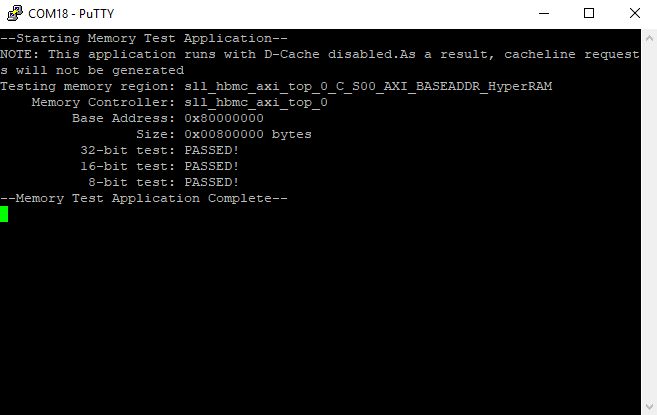
System Design - Vivado
| HTML |
|---|
<!--
Description of Block Design, Constrains...
BD Pictures from Export...
--> |
Block Design
Constrains
Basic module constrains
| Code Block | ||||
|---|---|---|---|---|
| ||||
set_property BITSTREAM.GENERAL.COMPRESS TRUE [current_design]
set_property BITSTREAM.CONFIG.CONFIGRATE 50 [current_design]
set_property CONFIG_VOLTAGE 3.3 [current_design]
set_property CFGBVS VCCO [current_design]
set_property BITSTREAM.CONFIG.SPI_32BIT_ADDR YES [current_design]
set_property BITSTREAM.CONFIG.SPI_BUSWIDTH 4 [current_design]
set_property BITSTREAM.CONFIG.M1PIN PULLNONE [current_design]
set_property BITSTREAM.CONFIG.M2PIN PULLNONE [current_design]
set_property BITSTREAM.CONFIG.M0PIN PULLNONE [current_design]

set_property BITSTREAM.CONFIG.USR_ACCESS TIMESTAMP [current_design]
|
Design specific constrain
| Code Block | ||||
|---|---|---|---|---|
| ||||
set_property PACKAGE_PIN A13 [get_ports HB_CLK0_0]
set_property PACKAGE_PIN A14 [get_ports HB_CLK0n_0]

set_property PACKAGE_PIN E17 [get_ports {HB_dq_0[0]}]
set_property PACKAGE_PIN B17 [get_ports {HB_dq_0[1]}]
set_property PACKAGE_PIN F18 [get_ports {HB_dq_0[2]}]
set_property PACKAGE_PIN F16 [get_ports {HB_dq_0[3]}]
set_property PACKAGE_PIN G17 [get_ports {HB_dq_0[4]}]
set_property PACKAGE_PIN D18 [get_ports {HB_dq_0[5]}]
set_property PACKAGE_PIN B18 [get_ports {HB_dq_0[6]}]
set_property PACKAGE_PIN A16 [get_ports {HB_dq_0[7]}]


set_property PACKAGE_PIN E18 [get_ports HB_RWDS_0]

set_property PACKAGE_PIN D17 [get_ports HB_CS1n_0]
set_property PACKAGE_PIN J17 [get_ports HB_RSTn_0]

#set_property PACKAGE_PIN A18 [get_ports HB_CS0n_0 ]
#set_property PACKAGE_PIN J18 [get_ports HB_INTn_0 ]
#set_property PACKAGE_PIN C17 [get_ports HB_RSTOn_0]


#
# FPGA Pin Voltage assignment
#
set_property IOSTANDARD LVCMOS18 [get_ports HB_CLK0_0]
set_property IOSTANDARD LVCMOS18 [get_ports HB_CLK0n_0]
set_property IOSTANDARD LVCMOS18 [get_ports {HB_dq_0[*]}]
set_property IOSTANDARD LVCMOS18 [get_ports HB_CS1n_0]
set_property IOSTANDARD LVCMOS18 [get_ports HB_RSTn_0]
set_property IOSTANDARD LVCMOS18 [get_ports HB_RWDS_0]

#set_property IOSTANDARD LVCMOS18 [get_ports HB_CS0n_0]
#set_property IOSTANDARD LVCMOS18 [get_ports HB_INTn_0]
#set_property IOSTANDARD LVCMOS18 [get_ports HB_RSTOn_0]

#set_property PULLUP true [get_ports HB_RSTOn_0]
#set_property PULLUP true [get_ports HB_INTn_0]

#
#Hyperbus Clock - change according to clk pin on PLL
#
create_generated_clock -name clk_0   -source [get_pins msys_i/clk_wiz_0/inst/mmcm_adv_inst/CLKIN1] -master_clock sys_clock [get_pins msys_i/clk_wiz_0/inst/mmcm_adv_inst/CLKOUT0]
create_generated_clock -name clk_90  -source [get_pins msys_i/clk_wiz_0/inst/mmcm_adv_inst/CLKIN1] -master_clock sys_clock [get_pins msys_i/clk_wiz_0/inst/mmcm_adv_inst/CLKOUT1]
create_generated_clock -name clk_180 -source [get_pins msys_i/clk_wiz_0/inst/mmcm_adv_inst/CLKIN1] -master_clock sys_clock [get_pins msys_i/clk_wiz_0/inst/mmcm_adv_inst/CLKOUT2]

#
#100Mhz clock freqeuncy - change accordingly
#
set hbus_freq_ns   10

set dqs_in_min_dly -0.5
set dqs_in_max_dly  0.5

set HB_dq_ports    [get_ports HB_dq_0[*]]

#
#Create RDS clock and RDS virtual clock
#
create_clock -period $hbus_freq_ns -name rwds_clk      [get_ports HB_RWDS_0]
create_clock -period $hbus_freq_ns -name virt_rwds_clk

#
#Input Delay Constraint -  HB_RWDS-HB_DQ
#
set_input_delay -clock [get_clocks virt_rwds_clk]             -max ${dqs_in_max_dly} ${HB_dq_ports}
set_input_delay -clock [get_clocks virt_rwds_clk] -clock_fall -max ${dqs_in_max_dly} ${HB_dq_ports} -add_delay

set_input_delay -clock [get_clocks virt_rwds_clk]             -min ${dqs_in_min_dly} ${HB_dq_ports} -add_delay
set_input_delay -clock [get_clocks virt_rwds_clk] -clock_fall -min ${dqs_in_min_dly} ${HB_dq_ports} -add_delay

set_multicycle_path -setup -end -rise_from [get_clocks virt_rwds_clk] -rise_to [get_clocks rwds_clk] 0
set_multicycle_path -setup -end -fall_from [get_clocks virt_rwds_clk] -fall_to [get_clocks rwds_clk] 0

set_false_path  -fall_from [get_clocks virt_rwds_clk] -rise_to [get_clocks rwds_clk] -setup
set_false_path  -rise_from [get_clocks virt_rwds_clk] -fall_to [get_clocks rwds_clk] -setup
set_false_path  -fall_from [get_clocks virt_rwds_clk] -fall_to [get_clocks rwds_clk] -hold
set_false_path  -rise_from [get_clocks virt_rwds_clk] -rise_to [get_clocks rwds_clk] -hold

set_false_path -from [get_clocks clk_0] -to [get_clocks rwds_clk]
set_false_path -from [get_clocks rwds_clk] -to [get_clocks clk_0]

#
#Output Delay Constraint -  HB_CLK0-HB_DQ
#

create_generated_clock -name HB_CLK0_0 -source [get_pins */*/*/U_IO/U_CLK0/dq_idx_[0].ODDR_inst/C] -multiply_by 1 -invert [get_ports HB_CLK0_0]

set_output_delay -clock [get_clocks HB_CLK0_0] -min -1.000 ${HB_dq_ports}
set_output_delay -clock [get_clocks HB_CLK0_0] -max  1.000 ${HB_dq_ports}
set_output_delay -clock [get_clocks HB_CLK0_0] -min -1.000 ${HB_dq_ports} -clock_fall -add_delay
set_output_delay -clock [get_clocks HB_CLK0_0] -max  1.000 ${HB_dq_ports} -clock_fall -add_delay


set_false_path -from [get_pins */*/*/U_HBC/*/dq_io_tri_reg/C] -to ${HB_dq_ports}

set_false_path -from * -to [get_pins */*/inst/*/i_iavs0_270_rstn_1_reg/CLR]
set_false_path -from * -to [get_pins */*/inst/*/i_iavs0_270_rstn_2_reg/CLR]
set_false_path -from * -to [get_pins */*/inst/*/i_iavs0_270_rstn_3_reg/CLR]
|
Software Design - SDK/HSI
| HTML |
|---|
<!--
optional chapter
separate sections for different apps
--> |
For SDK project creation, follow instructions from:
Application
memory_tests
Xilinx default memory test.
Additional Software
| HTML |
|---|
<!--
Add Description for other Software, for example SI CLK Builder ...
--> |
No additional software is needed.
Appx. A: Change History and Legal Notices
Document Change History
To get content of older revision got to "Change History" of this page and select older document revision number.
| HTML |
|---|
<!--
Generate new entry:
1:add new row below first
2:Copy Page Information Macro(date+user) Preview, Page Information Macro Preview
3.Update Metadate =Page Information Macro Preview+1
--> |
...
- 2018.2 release
...
...
- Documentation update
...
...
- 2017.4 release
...
Overview
Content Tools