Page History
...
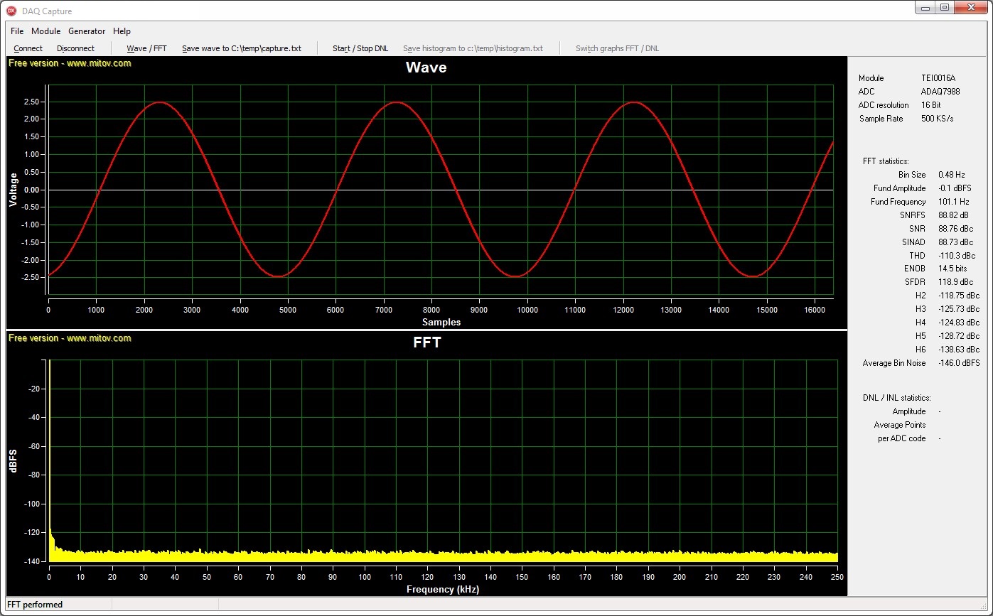
FFT - 101.09 Hz sine wave - 1024 kSamples
| Scroll Title | ||||
|---|---|---|---|---|
| ||||
|
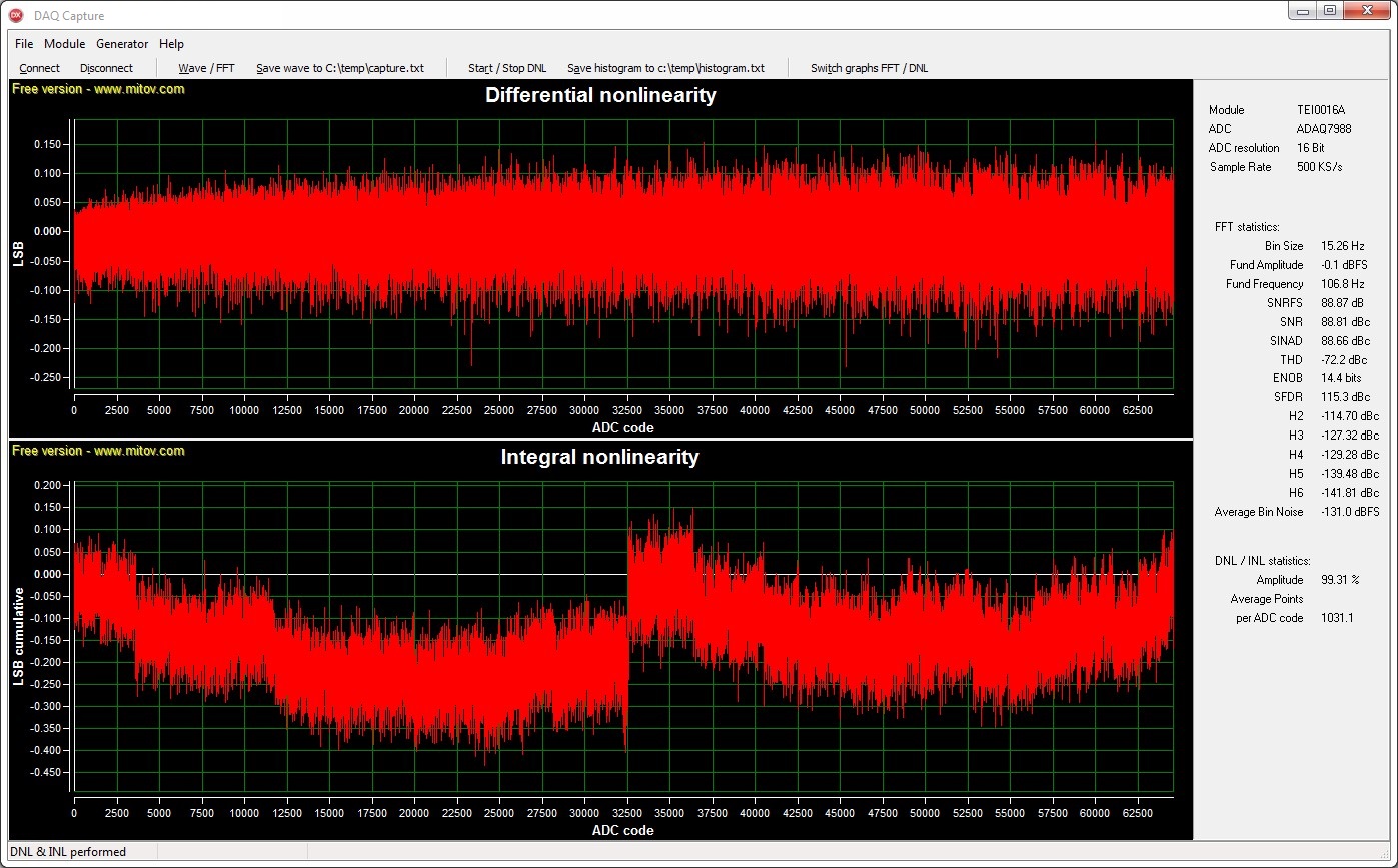
DNL - 101.09 Hz sine wave - 64 MSamples
| scroll-title | ||||
|---|---|---|---|---|
| anchor | Figure_OV_MC | |||
| title | ||||
|
Control elements
| scroll-title | ||||
|---|---|---|---|---|
| anchor | Figure_OV_MC | |||
| title | ||||
|

Top row:
The section Module contains radio buttons for setting up the parameters:
Gain - Select the signal / wave pre-amplification.
Samples FFT - Select the sample length of consecutive datapoints data points for the FFT analysis.
Samples DNL - Select the non consecutive size of datapoints data points for a DNL analysis.
Input Span ComporessionCompression - Feature of modules TEI0015 and TEI0023. Reduces , which reduces ADC reference voltage to 0.8.
High-Z Mode - Feature of modules TEI0015 and TEI0023. Reduces , which reduces ADC current consumption.
The section Generator controls the square wave generator.
The section Help contains links to the product page of every module and information about the program.
...
The DNL analysis assumes a sine wave input. The validity of its results depends heavily on the quality of the sine wave input signal. The better the sine wave input signal the more meaningfull meaningful the results will become.
The sine wave should have a SINAD (signal-to-interference ratio including noise and distortion) value of at leat 75 dBc and an amplitude just above 100 %. Therefore some clipping occurs and all ADC codes are present in the analysis. The sample length should ensure the average data points per ADC code to be well above 150.
An other aid for good results is the input frequency. The construction of the modules leads to a desired input frequency of 101.09 Hz. Best practice is to supply the input signal differentially.
BILD EINFÜGEN
Usage
Apply a signal to the modules inputs. Connect a single module to your PC and start the program. Press Connect for a connection to the module. A connection applies the default gain Gain of 1, enables the buttons Wave/FFT, DNL/INL and the sections Module and Generator.
Select values for pre-amplification
BILD EINFÜGEN
Gain, Sample FFT respectively Samples DNL gain, sample length and module specific features as you like. Press Wave / FFT or DNL / INL to run the analysis.
...
After a FFT analysis, the graphs are plotted, the signal statistics will be evaluated and the button Save wave to C:\temp\capture.txt is enabled. The button stores the Integer wave values from the ADC as text-file for interaction with the demo data capture Data Capture.
DNL analysis:
A DNL consists of two steps, first a FFT analysis, second the DNL analysis. Following the DNL analysis, the buttons Save DNL histogramm to c:\temp\histogram.txt and Show DNL / INL (Show Wave / FFT) will be enabled. The statistics for DNL are updated.
...
Overview
Content Tools