Page History
Table of Content
| Table of Contents | ||
|---|---|---|
|
Intention
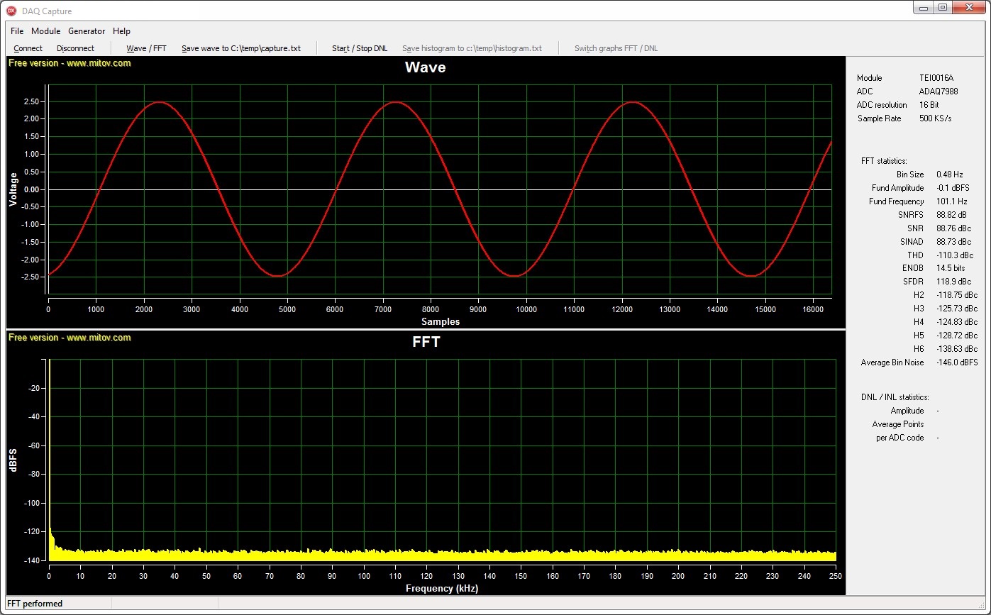
This tool is intended to show the capabilities of the ADCs of the module TEI0015 via FFT and DNL analysis. These two analyses complement each other.
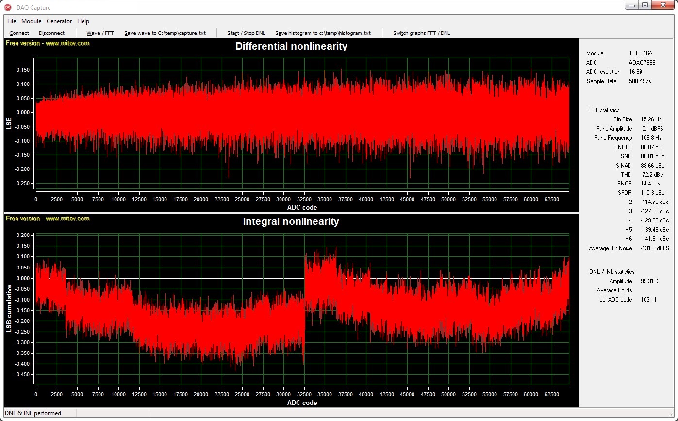
To show the quality of the input signal the well known FFT (Fast Fourier Transformation) can be used. The overall precision of the ADC can be evaluated by DNL and INL (Differential / Integral non linearity) analysis.
Download
Compressed folder, containing all necessary files for the demo - Download-Link
The compressed folder needs to be extracted, so that the contend can be used inside other programs.
The demo itself is an executable file and requires none additional software to be installed.
| Excerpt | ||||||||||||||||||||||||||||||||||||||||||
|---|---|---|---|---|---|---|---|---|---|---|---|---|---|---|---|---|---|---|---|---|---|---|---|---|---|---|---|---|---|---|---|---|---|---|---|---|---|---|---|---|---|---|
FFT - 101.09 Hz sine wave - 1024 kSamples
DNL - 101.09 Hz sine wave - 64 MSamples
Control elements
Top row: Bottom row: The following buttons are only enabled when a connection is established and after an analysis has been performed. During an analysis these buttons are disabled. Wave / FFT - Triggers a FFT analysis according to the parameters set in the section Module. Input Signal for a DNL analysisThe DNL analysis assumes a sine wave input. The validity of its results depends heavily on the quality of the sine wave input signal. The better the sine wave input signal the more meaningful the results will become. The sine wave should have an amplitude just above 100 %, therefore some clipping occurs and all ADC codes are present in the analysis. The sample length should ensure the average data points per ADC code to be well above 150. These values are visible in the lower part of the statistic section to the right under DNL / INL statistics: . An other aid for good results is the input frequency. The construction of the modules leads to a desired input frequency of 101.09 Hz. Best practice is to supply the input signal differentially. UsageApply a signal to the modules inputs. Connect a single module to your PC and start the program. Press Connect for a connection to the module. A connection applies the default Gain of 1, enables the buttons Wave / FFT, DNL / INL and the sections Module and Generator.
Select values for pre-amplification Gain, Sample FFT respectively Samples DNL and module specific features as you like. Press Wave / FFT or DNL / INL to run the analysis. During operation, the sections Module, Generator and most buttons will be disabled and afterwards re-enabled. Additional buttons / functions are available after an analysis. FFT analysis: DNL analysis: Disconnecting from the module or closing the program disables all module specific features and the square wave generator. |

Overview
Content Tools