Page History
...
The demo is offered in two variants, one which is stored into the embedded nonvolatile non-volatile memory (eNVM) and the other executed from the external DDR3/L SDRAM memory.
Refer to http://trenz.org/te0808tem0002-info for the current online version of this manual and other available documentation.
Key Features
| Page properties | ||||
|---|---|---|---|---|
| ||||
Notes :
|
...
| Excerpt |
|---|
|
...
| Scroll Title | |||||||||||||||||||||||||||||||||
|---|---|---|---|---|---|---|---|---|---|---|---|---|---|---|---|---|---|---|---|---|---|---|---|---|---|---|---|---|---|---|---|---|---|
| |||||||||||||||||||||||||||||||||
|
Release Notes and Know Issues
...
| Page properties | ||||
|---|---|---|---|---|
| ||||
Notes :
|
Basic description of TE Board Part Files is available on TE Board Part Files.
Complete List is available on <design name>/board_files/*_board_files.csv
Design supports following modules:
| Scroll Title | ||||||||||||||||||||||||||||||||||||
|---|---|---|---|---|---|---|---|---|---|---|---|---|---|---|---|---|---|---|---|---|---|---|---|---|---|---|---|---|---|---|---|---|---|---|---|---|
| ||||||||||||||||||||||||||||||||||||
|
<<============== ABKLÄREN OB BEIDE HW-Revisionen unterstütz werden
Note: Design contains also Board Part Files for TE0808 only configuration, this boart part files are not used for this reference design.
Hardware Requirements:
Hardware Requirements:
| Scroll Title | ||||||||||||||||||||||||||||||
|---|---|---|---|---|---|---|---|---|---|---|---|---|---|---|---|---|---|---|---|---|---|---|---|---|---|---|---|---|---|---|
| ||||||||||||||||||||||||||||||
|
...
| Page properties | ||||
|---|---|---|---|---|
| ||||
Notes :
|
...
Content of the zip archievearchive:
- Libero Hardware Project
- SoftConsole Software Project
- Board configuration file
- Manual
...
| Scroll Title | |||||||||||||||||||||||||||
|---|---|---|---|---|---|---|---|---|---|---|---|---|---|---|---|---|---|---|---|---|---|---|---|---|---|---|---|
| |||||||||||||||||||||||||||
|
...
| Scroll Title | ||||
|---|---|---|---|---|
|
...
Download
Reference Design is only usable with the specified Libero/SoftConsole version. Usage of a different Microsemi Software versions is not recommanded.
| Page properties | |||||
|---|---|---|---|---|---|
| |||||
| Scroll Title | |||||
| |||||
| Scroll Table Layout | |||||
| orientation | portrait | ||||
| sortDirection | ASC | ||||
| repeatTableHeaders | default | style | widths | ||
| sortByColumn | 1 | ||||
| sortEnabled | false | ||||
| cellHighlighting | true | ||||
File | File-Extension | Description | |||
| BIF-File | *.bif | File with description to generate Bin-File | |||
| BIN-File | *.bin | Flash Configuration File with Boot-Image (Zynq-FPGAs) | |||
| BIT-File | *.bit | FPGA (PL Part) Configuration File | |||
| DebugProbes-File | *.ltx | Definition File for Vivado/Vivado Labtools Debugging Interface | |||
Debian SD-Image | *.img | Debian Image for SD-Card | |||
| Diverse Reports | --- | Report files in different formats | |||
| Hardware-Platform-Specification-Files | *.xsa | Exported Vivado Hardware Specification for Vitis and PetaLinux | |||
| LabTools Project-File | *.lpr | Vivado Labtools Project File | |||
MCS-File | *.mcs | Flash Configuration File with Boot-Image (MicroBlaze or FPGA part only) | |||
MMI-File | *.mmi | File with BRAM-Location to generate MCS or BIT-File with *.elf content (MicroBlaze only) | |||
| OS-Image | *.ub | Image with Linux Kernel (On Petalinux optional with Devicetree and RAM-Disk) | |||
| Image | --- | Generic Linux kernel binary image file | |||
| Software-Application-File | *.elf | Software Application for Zynq or MicroBlaze Processor Systems | |||
SREC-File | *.srec | Converted Software Application for MicroBlaze Processor Systems | |||
| Device Tree Blob File | *.dtb | Contains a Device Tree Blob | |||
| Scroll Title | |||||
| |||||
| Scroll Table Layout | |||||
| orientation | portrait | ||||
| sortDirection | ASC | ||||
| repeatTableHeaders | default | style | widths | ||
| sortByColumn | 1 | ||||
| sortEnabled | false | ||||
| cellHighlighting | true | ||||
File | File-Extension | Description | |||
| Constrain files | .pdc | Pin constrain file | .sdc | Time constrain | |
| Programming files | .ipd | Libero SoC in system programming via JTAG, not exportable | .stp / .dat | In system programming via JTAG | .dat / .stp / .spi | In system programming of SPI-slave | .spi | In system programming of Cortex-M3 |
| SmartDesign component files | .sdb / . cfx | ||||
| Log files | .log / .rtp / .xml / .scv / .txt | ||||
| Simulation Files | .mem / .bfm / .dat /.txt / .do | ||||
| Designer directory | .adb | Microsemi Designer project files | .ba / .v(hd) / .stp / .tcl | Script-files to run designer | .prj_des | Local revision project file |
| Input source files (hdl directory ) | .vhd / .v / .h | .edn / _syn.prj / .srr | Synplify log file | .psp | Precision project file | precision.log | Precision logfile | .tcl | Script-files to runsynthesis | .edn | Synthesis output file |
| Generally software related | *.elf | Software Application file for Processor Systems | |||
Download
Reference Design is only usable with the specified Libero/SoftConsole version. Usage of a different Microsemi Software versions is not recommanded.
| Page properties | ||||
|---|---|---|---|---|
| ||||
|
Reference Design is available on:
- TEM0002 "Webserver Demo" Reference Design <<================ ADD / Convert to - LINK
Preparations
The reference design is available as a prebuild zip archive, which contains hard and soft ware project folders and the board configuration file "microsemi-smartfusion2-smartberry-ddr.cfg" . It was created and tested in windows environment.
The zip archive must to be extracted. The board configuration file needs to copied into your SoftConsole installation directory. When taking the required SoftConsole version into account, SoftConsole version 6.2, and the default installation path, copy the board configuration file into:
"C:\Microsemi\SoftConsole_v6.2\openocd\share\openocd\scripts\board\"
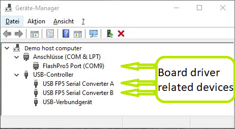
Connect the board via USB cable to your demo host computer. Check in the Windows Device Manager the appearance of the tree board driver related devices:
- FlashPro5 Port (ComX)
- USB FP5 Serial Converter A
- USB FP5 Serial Converter B
The Device Manager is accessible via "Right mouse click context menu" from the Windows Start Menu Button.
Connect the boards Ethernet port to your demo host computer. The demo is configured to establish a network connection via the DHCP protocol, therefore a free router / network port can be used.
A direct port to port connection between the demo host computer and the board is also possible but requires to reconfigure the software project.
Hardware design flashing
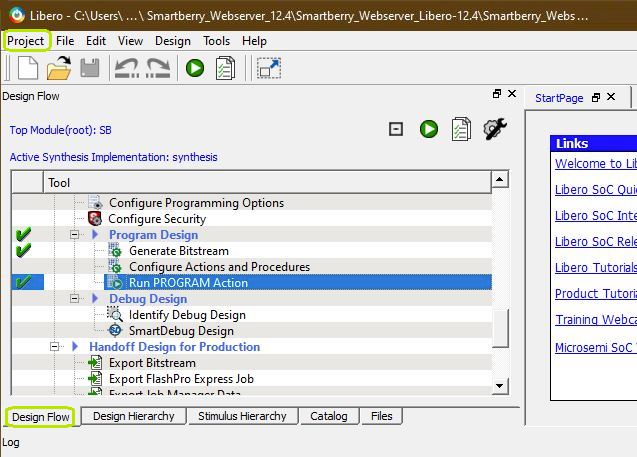
Open Libero 12.4, in the to left corner, open the demo hardware project via "Project > Open Project" and point to file dialog to the demo archives hardware project dicsk:\Path_to_the_hardware_project_inside_the_archive\ , double left mouse click onto the project file "Smartberry_Webserver.prjx" to open it.
The board is automatically selected and setup to be flashed by Libero.
In the upper left section of Libero, select the tab "Design Flow" and flash it to the board via "Program Design > and double left mouse click onto Run PROGRAM Action".
Warnings can be ignored.
The hardware design is volatile and therefore lost when powering the board down.
Software project flashing
Open SoftConsole 6.2 and point the "Workspace:" to the folder "SmartberrySoftconsole-6.2" inside the demo folder.
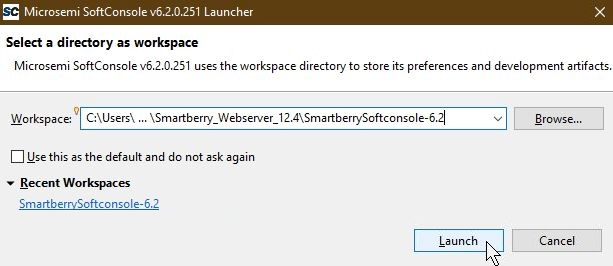
Subsequently the program opens.
The SoftConsole display to the left the projects which the Workspace contains.
The two demo projects "Smartberry_Webserver_6.2" and "Smartberry_Webserver_DDR_6.2" are identical variants of the demo, they only differ in the memory location. The first one is stored in embedded non volatile memory (eNVM) and the later is stored volatile in the external DDR ram and therefore lost during power down.
Before flashing the demo, open a comport terminal to the boards comport, so that its messages about the used IP Adress and Mode can be captured.
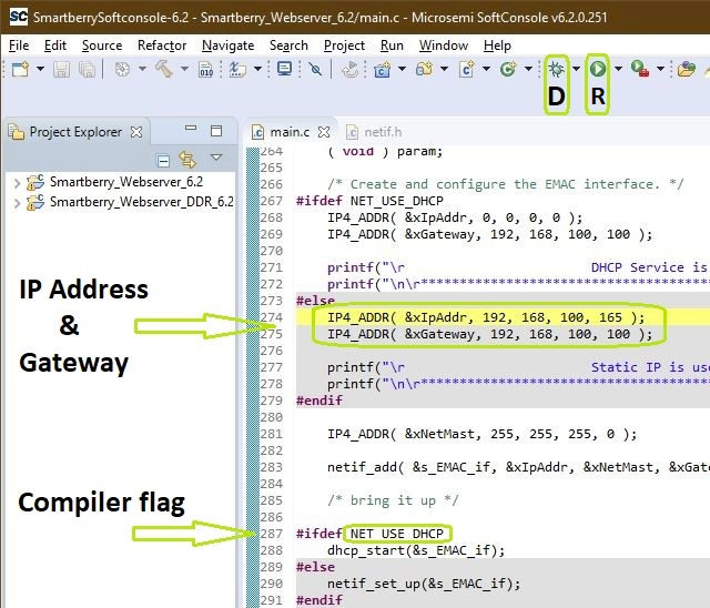
To simply run the demo press the triangle right to the button marked with a "R" in the picture above and select the variant of the demo.
Pressing the triangle next to the button marked with "D" let you select which variant to be executed in debug mode.
Debug controlls - Resume - Pause - Stop
![]()
Switch between Debug and Run perspective (upper right corner program window)
![]()
Static IP configuration
To disengaging the DHCP mode one has to setup up an IP Address in the code unit "main.c" line 274, a gateway address has is not required. Alternativly, the demo hosts IP Address can be changed.
Furthermore the corresponding compiler flag needs to be deleted in the project setting. To do so, in the "Project Explorer" tab, right mouse click onto the project and select Properties in the appearing menu.
In the left section of the properties window select "C/C++ Build > Settings" in the right section select the tab "Tool Settings > GNU ARM Cross C Compiler > Preprocessor" under "Defined symbols (-D)" delete the compiler flag "NET_USE_DHCP" and press "Apply". Confirm the following dialog and press "Cancel".
Lastly, the project needs to be recompiled. In the top menu of the SoftConsole select "Project > Build ALL / Build Project".
Warnings can be ignored.
Demo usage
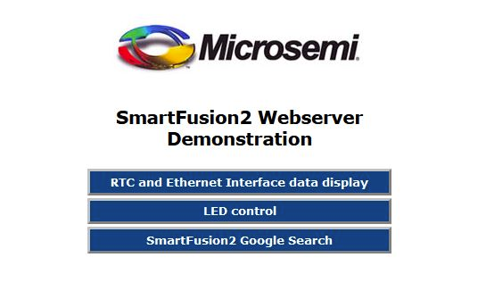
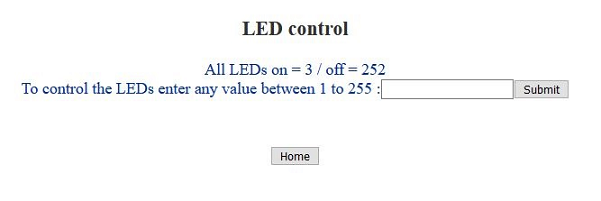
Open a new tab in a web browser and enter the IP Adress from the comport terminal.
Pictures of the servers pages.
...
Design Flow
| Page properties | ||||
|---|---|---|---|---|
| ||||
Notes :
|
| Note |
|---|
Reference Design is available with and without prebuilt files. It's recommended to use TE prebuilt files for first lunch. |
Trenz Electronic provides a tcl based built environment based on Xilinx Design Flow.
See also:
Xilinx Development Tools#XilinxSoftware-BasicUserGuidesVivado Projects - TE Reference DesignProject Delivery.
The Trenz Electronic FPGA Reference Designs are TCL-script based project. Command files for execution will be generated with "_create_win_setup.cmd" on Windows OS and "_create_linux_setup.sh" on Linux OS.
TE Scripts are only needed to generate the vivado project, all other additional steps are optional and can also executed by Xilinx Vivado/SDK GUI. For currently Scripts limitations on Win and Linux OS see: Project Delivery Currently limitations of functionality
_create_win_setup.cmd/_create_linux_setup.sh and follow instructions on shell: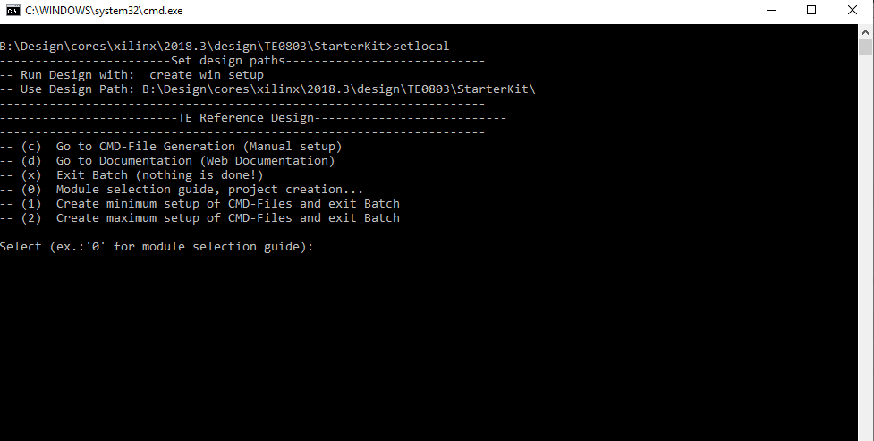
Press 0 and enter to start "Module Selection Guide"(optional Win OS) Generate Virtual Drive or use short directory for the reference design (for example x:\<design name>)Create Project (follow instruction of the product selection guide), settings file will be configured automatically during this process)(optional for manual changes) Select correct device and Xilinx install path on "design_basic_settings.cmd" and create Vivado project with "vivado_create_project_guimode.cmd"Note: Select correct one, see alsoTE Board Part FilesImportant: Use Board Part Files, which ends with *_tebf0808
Create XSA and export to prebuilt folderRun on Vivado TCL: TE::hw_build_design -export_prebuiltNote: Script generate design and export files into \prebuilt\hardware\<short dir>. Use GUI is the same, except file export to prebuilt folder
Create Linux (bl31.elf, uboot.elf , Image and system.dtb) with exported XSAXSA is exported to "prebuilt\hardware\<short name>"Note: HW Export from Vivado GUI create another path as default workspace.Create Linux images on VM, see PetaLinux KICKstartUse TE Template from /os/petalinux/Execute the script file for Debian/Ubuntu
Add Linux files (bl31.elf, uboot.elf , Image and system.dtb) to prebuilt folder"prebuilt\os\petalinux\<ddr size>" or "prebuilt\os\petalinux\<short name>"
Generate Programming Files with VitisRun on Vivado TCL: TE::sw_run_vitis -allNote: Scripts generate applications and bootable files, which are defined in "sw_lib\apps_list.csv"(alternative) Start SDK with Vivado GUI or start with TE Scripts on Vivado TCL: TE::sw_run_vitisNote: TCL scripts generate also platform project, this must be done manuelly in case GUI is used. See Vitis
Preparing SD card for SD Filesystem and hard disk for HD Filesystem → See Programming section
Launch
| Page properties | ||||
|---|---|---|---|---|
| ||||
Note:
|
For basic board setup, LEDs... see: TEBF0808 Getting Started
Programming
| Note |
|---|
Check Module and Carrier TRMs for proper HW configuration before you try any design. |
Xilinx documentation for programming and debugging: Vivado/SDK/SDSoC-Xilinx Software Programming and Debugging
Get prebuilt boot binaries
- _create_win_setup.cmd/_create_linux_setup.sh and follow instructions on shell
- Press 0 and enter to start "Module Selection Guide"
- Select assembly version
- Validate selection
- Select Create and open delivery binary folder
Note: Folder (<project foler>/_binaries_<Artikel Name>) with subfolder (boot_<app name>) for different applications will be generated
QSPI
Not used in this example.
SD
- Format the SD Card with SD Card Formatter or other tool
- Write the Debian image or Ubuntu image file on SD Card with Win32DiskImager
- It will automatically in BOOT directory two DTB file generated
- system_sd.dtb : This file ist used , if the root file system is located on SD card.
- system_harddisk.dtb : This file ist used , if the root file system is located on hard disk.
- Note: To use one of the DTB files, this file must be renamed to system.dtb
- Rename the system_sd.dtb file in BOOT directory to system.dtb
- Copy Petalinux Image (not use image.ub), system.dtb and Boot.bin files on SD-Card.
- use files from (<project foler>/_binaries_<Articel Name>)/boot_linux from generated binary folder,see: Get prebuilt boot binaries
- or use prebuilt file location, see <design_name>/prebuilt/readme_file_location.txt
- Set Boot Mode to SD-Boot.
- Depends on Carrier, see carrier TRM.
- Insert SD-Card in SD-Slot.
JTAG
Not used on this Example.
Usage
- Prepare HW like described on section TE0808 StarterKit#Programming
- Connect UART USB (JTAG XMOD)
- Select SD Card as Boot Mode (or QSPI - depending on step 1)
Note: See TRM of the Carrier, which is used. - (Optional) Insert PCIe Card (detection depends on Linux driver. Only some basic drivers are installed)
- (Optional) Connect Sata Disc
- (Optional) Connect DisplayPort Monitor (List of usable Monitors: https://www.xilinx.com/support/answers/68671.html)
- (Optional) Connect Network Cable
- Power On PCB
Note: 1. ZynqMP Boot ROM loads PMU Firmware and FSBL from SD into OCM, 2. FSBL loads ATF(bl31.elf) and U-boot from SD/QSPI into DDR, 3. U-boot load Linux from SD into DDR.
Linux
- Open Serial Console (e.g. putty)
- Speed: 115200
- COM Port: Win OS, see device manager, Linux OS see dmesg |grep tty (UART is *USB1)
- Linux Console:
Note: Wait until Linux boot finished For Linux Login use:- User Name: root
- Password: root
- You can use Linux shell now.
- Debian Desktop
- Use connected mouse + keyboard for interaction with GUI
- Start the GUI with the command : startx
- Web Browser Dillo open console and type dillo or use browser
- open console and start video or audio with "mplayer <video or audio file>"
- Ubuntu Desktop
- Use connected mouse + keyboard for interaction with GUI
- Start the GUI with the command : startx
- Web Browser Mozilla firefox can be used.
- Audio or Vider file can also be performed directly in GUI
Hard Disk (optional)
To locate root file system on Hard disk:
- Plug in SD Card that you have prepared mit root file system
- Plug in Hard Disk in Sata port on the carrier board
- Format the hard disk by the following command:
- mkfs.ext4 /dev/sda
- Edit the fstab file in directory /etc/ to mount hard disk by the following commands:
- mkdir /media/harddisk
- nano /etc/fstab
- Add this line to the fstab file and save it : /dev/sda /media/harddisk/ defaults 0 3
- Reboot
- Copy entire root file system in direcroty ROOTFS from SD card to hard disk by the following commands:
- cd /media/ROOTFS
- cp -r ./ /media/harddisk
- Edit the fstab file in directory /media/harddisk/etc/ by the following commands and save it:
- nano /media/harddisk/etc/fstab
- Edit this line to the fstab file : /dev/sda /media/harddisk/ defaults 0 1
- Comment this line: #/dev/mmcblk1p2 /media/ROOTFS defaults 0 1
- Shutdown the system
- Format the SD card
- Rename the Device Tree Blob file system_harddisk.dtb to system.dtb
- Copy the following files to SD Card:
- Image
- BOOT.bin
- system.dtb
- Plug in the SD Card and turn on the system
Vivado Hardware Manager
| Page properties | ||||
|---|---|---|---|---|
| ||||
Note:
|
System Design - Vivado
| Page properties | ||||
|---|---|---|---|---|
| ||||
Note:
|
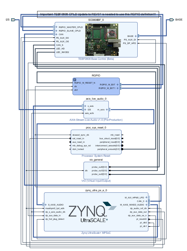
Block Design
| Scroll Title | ||||
|---|---|---|---|---|
| ||||
 |
PS Interfaces
| Page properties | ||||
|---|---|---|---|---|
| ||||
Note:
|
Activated interfaces:
...
| anchor | Table_PSI |
|---|---|
| title | PS Interfaces |
...
Constrains
Basic module constrains
| Code Block | ||||
|---|---|---|---|---|
| ||||
set_property BITSTREAM.GENERAL.COMPRESS TRUE [current_design]
set_property BITSTREAM.CONFIG.UNUSEDPIN PULLNONE [current_design]
|
| Code Block | ||||
|---|---|---|---|---|
| ||||
#System Controller IP
  #LED_HD SC0 J3:31
  #LED_XMOD SC17 J3:48
  #CAN RX SC19 J3:52 B47_L2_P in
  #CAN TX SC18 J3:50 B47_L2_N out
  #CAN S  SC16 J3:46 B47_L3_N out
set_property PACKAGE_PIN J14 [get_ports BASE_sc0]
set_property PACKAGE_PIN G13 [get_ports BASE_sc5]
set_property PACKAGE_PIN J15 [get_ports BASE_sc6]
set_property PACKAGE_PIN K15 [get_ports BASE_sc7]
set_property PACKAGE_PIN A15 [get_ports BASE_sc10_io]
set_property PACKAGE_PIN B15 [get_ports BASE_sc11]
set_property PACKAGE_PIN C13 [get_ports BASE_sc12]
set_property PACKAGE_PIN C14 [get_ports BASE_sc13]
set_property PACKAGE_PIN E13 [get_ports BASE_sc14]
set_property PACKAGE_PIN E14 [get_ports BASE_sc15]
set_property PACKAGE_PIN A13 [get_ports BASE_sc16]
set_property PACKAGE_PIN B13 [get_ports BASE_sc17]
set_property PACKAGE_PIN A14 [get_ports BASE_sc18]
set_property PACKAGE_PIN B14 [get_ports BASE_sc19]
set_property IOSTANDARD LVCMOS18 [get_ports BASE_sc0]
set_property IOSTANDARD LVCMOS18 [get_ports BASE_sc5]
set_property IOSTANDARD LVCMOS18 [get_ports BASE_sc6]
set_property IOSTANDARD LVCMOS18 [get_ports BASE_sc7]
set_property IOSTANDARD LVCMOS18 [get_ports BASE_sc10_io]
set_property IOSTANDARD LVCMOS18 [get_ports BASE_sc11]
set_property IOSTANDARD LVCMOS18 [get_ports BASE_sc12]
set_property IOSTANDARD LVCMOS18 [get_ports BASE_sc13]
set_property IOSTANDARD LVCMOS18 [get_ports BASE_sc14]
set_property IOSTANDARD LVCMOS18 [get_ports BASE_sc15]
set_property IOSTANDARD LVCMOS18 [get_ports BASE_sc16]
set_property IOSTANDARD LVCMOS18 [get_ports BASE_sc17]
set_property IOSTANDARD LVCMOS18 [get_ports BASE_sc18]
set_property IOSTANDARD LVCMOS18 [get_ports BASE_sc19]

# PLL
#set_property PACKAGE_PIN AH6 [get_ports {si570_clk_p[0]}]
#set_property IOSTANDARD LVDS [get_ports {si570_clk_p[0]}]
#set_property IOSTANDARD LVDS [get_ports {si570_clk_n[0]}]
# Clocks
#set_property PACKAGE_PIN J8 [get_ports {B229_CLK1_clk_p[0]}]
#set_property PACKAGE_PIN F25 [get_ports {B128_CLK0_clk_p[0]}]
# SFP
#set_property PACKAGE_PIN G8 [get_ports {B230_CLK0_clk_p}]
# B230_RX3_P
#set_property PACKAGE_PIN A4 [get_ports {SFP1_rxp}]
# B230_TX3_P
#set_property PACKAGE_PIN A8 [get_ports {SFP1_txp}]
# B230_RX2_P
#set_property PACKAGE_PIN B2 [get_ports {SFP2_rxp}]
# B230_TX2_P
#set_property PACKAGE_PIN B6 [get_ports {SFP2_txp}]

# Audio Codec
#LRCLK		  J3:49 B47_L9_N
#BCLK		    J3:51 B47_L9_P
#DAC_SDATA	J3:53 B47_L7_N
#ADC_SDATA	J3:55 B47_L7_P
set_property PACKAGE_PIN G14 [get_ports I2S_lrclk ]
set_property PACKAGE_PIN G15 [get_ports I2S_bclk ]
set_property PACKAGE_PIN E15 [get_ports I2S_sdin ]
set_property PACKAGE_PIN F15 [get_ports I2S_sdout ]
set_property IOSTANDARD LVCMOS18 [get_ports I2S_lrclk ]
set_property IOSTANDARD LVCMOS18 [get_ports I2S_bclk ]
set_property IOSTANDARD LVCMOS18 [get_ports I2S_sdin ]
set_property IOSTANDARD LVCMOS18 [get_ports I2S_sdout ]
|
Software Design - Vitis
| Page properties | ||||
|---|---|---|---|---|
| ||||
Note:
|
For SDK project creation, follow instructions from:
Application
...
| hidden | true |
|---|---|
| id | Comments |
----------------------------------------------------------
FPGA Example
scu
MCS Firmware to configure SI5338 and Reset System.
srec_spi_bootloader
TE modified 2019.2 SREC
Bootloader to load app or second bootloader from flash into DDR
Descriptions:
- Modified Files: blconfig.h, bootloader.c
- Changes:
- Add some console outputs and changed bootloader read address.
- Add bugfix for 2018.2 qspi flash
xilisf_v5_11
TE modified 2019.2 xilisf_v5_11
- Changed default Flash type to 5.
----------------------------------------------------------
Zynq Example:
zynq_fsbl
TE modified 2019.2 FSBL
General:
- Modified Files:main.c, fsbl_hooks.h/.c (search for 'TE Mod' on source code)
Add Files: te_fsbl_hooks.h/.c(for hooks and board)\n\
- General Changes:
- Display FSBL Banner and Device ID
Module Specific:
- Add Files: all TE Files start with te_*
- READ MAC from EEPROM and make Address accessible by UBOOT (need copy defines on uboot platform-top.h)
- CPLD access
- Read CPLD Firmware and SoC Type
- Configure Marvell PHY
zynq_fsbl_flash
TE modified 2019.2 FSBL
General:
- Modified Files: main.c
- General Changes:
- Display FSBL Banner
- Set FSBL Boot Mode to JTAG
- Disable Memory initialisation
ZynqMP Example:
----------------------------------------------------------
zynqmp_fsbl
TE modified 2019.2 FSBL
General:
- Modified Files: xfsbl_main.c, xfsbl_hooks.h/.c, xfsbl_board.h/.c(search for 'TE Mod' on source code)
- Add Files: te_xfsbl_hooks.h/.c (for hooks and board)\n\
- General Changes:
- Display FSBL Banner and Device Name
Module Specific:
- Add Files: all TE Files start with te_*
- Si5338 Configuration
- ETH+OTG Reset over MIO
zynqmp_fsbl_flash
TE modified 2019.2 FSBL
General:
- Modified Files: xfsbl_initialisation.c, xfsbl_hw.h, xfsbl_handoff.c, xfsbl_main.c
- General Changes:
- Display FSBL Banner
- Set FSBL Boot Mode to JTAG
- Disable Memory initialisation
zynqmp_pmufw
Xilinx default PMU firmware.
----------------------------------------------------------
General Example:
hello_te0820
Hello TE0820 is a Xilinx Hello World example as endless loop instead of one console output.
u-boot
U-Boot.elf is generated with PetaLinux. SDK/HSI is used to generate Boot.bin.
|
Reference Design is available on:
- TEM0002 "Webserver Demo" Reference Design
Preparations
The reference design is available as a prebuild zip archive, which contains hard and soft ware project folders and the board configuration file "microsemi-smartfusion2-smartberry-ddr.cfg" . It was created and tested in windows environment.
The zip archive must to be extracted. The board configuration file needs to copied into your SoftConsole installation directory. When taking the required SoftConsole version into account, SoftConsole version 6.2, and the default installation path, copy the board configuration file into:
"C:\Microsemi\SoftConsole_v6.2\openocd\share\openocd\scripts\board\"
mit thomas bereden
Connect the board via USB cable to your demo host computer. Check in the Windows Device Manager the appearance of the tree board driver related devices:
- FlashPro5 Port (ComX)
- USB FP5 Serial Converter A
- USB FP5 Serial Converter B
The Device Manager is accessible via "Right mouse click context menu" from the Windows Start Menu Button.
Connect the boards Ethernet port to your demo host computer. The demo is configured to establish a network connection via the DHCP protocol, therefore a free router / network port can be used.
A direct port to port connection between the demo host computer and the board is also possible but requires to reconfigure the software project.
Hardware design flashing
Open Libero 12.4, in the to left corner, open the demo hardware project via "Project > Open Project" and point to file dialog to the demo archives hardware project dicsk:\Path_to_the_hardware_project_inside_the_archive\ , double left mouse click onto the project file "Smartberry_Webserver.prjx" to open it.
The board is automatically selected and setup to be flashed by Libero.
In the upper left section of Libero, select the tab "Design Flow" and flash it to the board via "Program Design > and double left mouse click onto Run PROGRAM Action".
Warnings can be ignored.
The hardware design is volatile and therefore lost when powering the board down.
Software project flashing
Open SoftConsole 6.2 and point the "Workspace:" to the folder "SmartberrySoftconsole-6.2" inside the demo folder.
Subsequently the program opens.
The SoftConsole display to the left the projects which the Workspace contains.
The two demo projects "Smartberry_Webserver_6.2" and "Smartberry_Webserver_DDR_6.2" are identical variants of the demo, they only differ in the memory location. The first one is stored in embedded non volatile memory (eNVM) and the later is stored volatile in the external DDR ram and therefore lost during power down.
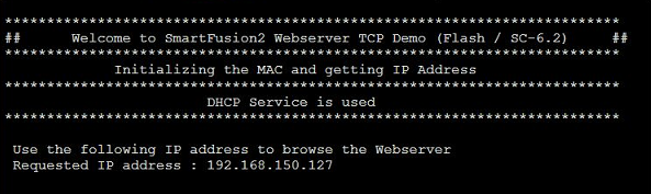
Before flashing the demo, open a comport terminal to the boards comport, so that its messages about the used IP Adress and Mode can be captured.
To simply run the demo press the triangle right to the button marked with a "R" in the picture above and select the variant of the demo.
Pressing the triangle next to the button marked with "D" let you select which variant to be executed in debug mode.
Debug controlls - Resume - Pause - Stop
![]()
Switch between Debug and Run perspective (upper right corner program window)
![]()
Static IP configuration
To disengaging the DHCP mode one has to setup up an IP Address in the code unit "main.c" line 274, a gateway address has is not required. Alternativly, the demo hosts IP Address can be changed.
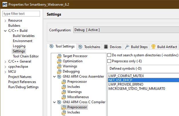
Furthermore the corresponding compiler flag needs to be deleted in the project setting. To do so, in the "Project Explorer" tab, right mouse click onto the project and select Properties in the appearing menu.
In the left section of the properties window select "C/C++ Build > Settings" in the right section select the tab "Tool Settings > GNU ARM Cross C Compiler > Preprocessor" under "Defined symbols (-D)" delete the compiler flag "NET_USE_DHCP" and press "Apply". Confirm the following dialog and press "Cancel".
Lastly, the project needs to be recompiled. In the top menu of the SoftConsole select "Project > Build ALL / Build Project".
Warnings can be ignored.
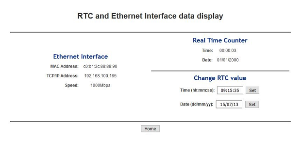
Demo usage
Open a new tab in a web browser and enter the IP Adress from the comport terminal.
Pictures of the servers pages.
Design Flow
| Page properties | ||||
|---|---|---|---|---|
| ||||
Notes :
|
| Note |
|---|
Reference Design is available with and without prebuilt files. It's recommended to use TE prebuilt files for first lunch. |
Trenz Electronic provides a tcl based built environment based on Xilinx Design Flow.
See also:
Xilinx Development Tools#XilinxSoftware-BasicUserGuidesVivado Projects - TE Reference DesignProject Delivery.
The Trenz Electronic FPGA Reference Designs are TCL-script based project. Command files for execution will be generated with "_create_win_setup.cmd" on Windows OS and "_create_linux_setup.sh" on Linux OS.
TE Scripts are only needed to generate the vivado project, all other additional steps are optional and can also executed by Xilinx Vivado/SDK GUI. For currently Scripts limitations on Win and Linux OS see: Project Delivery Currently limitations of functionality
_create_win_setup.cmd/_create_linux_setup.sh and follow instructions on shell:Press 0 and enter to start "Module Selection Guide"(optional Win OS) Generate Virtual Drive or use short directory for the reference design (for example x:\<design name>)Create Project (follow instruction of the product selection guide), settings file will be configured automatically during this process)(optional for manual changes) Select correct device and Xilinx install path on "design_basic_settings.cmd" and create Vivado project with "vivado_create_project_guimode.cmd"Note: Select correct one, see alsoTE Board Part FilesImportant: Use Board Part Files, which ends with *_tebf0808
Create XSA and export to prebuilt folderRun on Vivado TCL: TE::hw_build_design -export_prebuiltNote: Script generate design and export files into \prebuilt\hardware\<short dir>. Use GUI is the same, except file export to prebuilt folder
Create Linux (bl31.elf, uboot.elf , Image and system.dtb) with exported XSAXSA is exported to "prebuilt\hardware\<short name>"Note: HW Export from Vivado GUI create another path as default workspace.Create Linux images on VM, see PetaLinux KICKstartUse TE Template from /os/petalinux/Execute the script file for Debian/Ubuntu
Add Linux files (bl31.elf, uboot.elf , Image and system.dtb) to prebuilt folder"prebuilt\os\petalinux\<ddr size>" or "prebuilt\os\petalinux\<short name>"
Generate Programming Files with VitisRun on Vivado TCL: TE::sw_run_vitis -allNote: Scripts generate applications and bootable files, which are defined in "sw_lib\apps_list.csv"(alternative) Start SDK with Vivado GUI or start with TE Scripts on Vivado TCL: TE::sw_run_vitisNote: TCL scripts generate also platform project, this must be done manuelly in case GUI is used. See Vitis
Preparing SD card for SD Filesystem and hard disk for HD Filesystem → See Programming section
Launch
| Page properties | ||||
|---|---|---|---|---|
| ||||
Note:
|
Programming
Usage
System Design - Libero
| Page properties | ||||
|---|---|---|---|---|
| ||||
Note:
|
Smart Design
| Scroll Title | ||||
|---|---|---|---|---|
| ||||
|
Constrains
| Code Block | ||||
|---|---|---|---|---|
| ||||
set_property BITSTREAM.GENERAL.COMPRESS TRUE [current_design]
set_property BITSTREAM.CONFIG.UNUSEDPIN PULLNONE [current_design]
|
Software Design - SoftConsole
| Page properties | ||||
|---|---|---|---|---|
| ||||
Note:
|
Application
| Page properties | ||||
|---|---|---|---|---|
| ||||
---------------------------------------------------------- FPGA Example scuMCS Firmware to configure SI5338 and Reset System. srec_spi_bootloaderTE modified 2019.2 SREC Bootloader to load app or second bootloader from flash into DDR Descriptions:
xilisf_v5_11TE modified 2019.2 xilisf_v5_11
---------------------------------------------------------- Zynq Example: zynq_fsblTE modified 2019.2 FSBL General:
Module Specific:
zynq_fsbl_flashTE modified 2019.2 FSBL General:
ZynqMP Example: ---------------------------------------------------------- zynqmp_fsblTE modified 2019.2 FSBL General:
Module Specific:
zynqmp_fsbl_flashTE modified 2019.2 FSBL General:
zynqmp_pmufwXilinx default PMU firmware. ---------------------------------------------------------- General Example: hello_te0820Hello TE0820 is a Xilinx Hello World example as endless loop instead of one console output. u-bootU-Boot.elf is generated with PetaLinux. SDK/HSI is used to generate Boot.bin. |
SDK template in ./sw_lib/sw_apps/ available.
zynqmp_fsbl
TE modified 2019.2 FSBL
General:
- Modified Files: xfsbl_main.c, xfsbl_hooks.h/.c, xfsbl_board.h/.c(search for 'TE Mod' on source code)
- Add Files: te_xfsbl_hooks.h/.c (for hooks and board)\n\
- General Changes:
- Display FSBL Banner and Device Name
Module Specific:
- Add Files: all TE Files start with te_*
- Si5345 Configuration
- OTG+PCIe Reset over MIO
- I2C MUX for EEPROM MAC
zynqmp_fsbl_flash
TE modified 2019.2 FSBL
General:
- Modified Files: xfsbl_initialisation.c, xfsbl_hw.h, xfsbl_handoff.c, xfsbl_main.c
- General Changes:
- Display FSBL Banner
- Set FSBL Boot Mode to JTAG
- Disable Memory initialisation
zynqmp_pmufw
Xilinx default PMU firmware.
hello_te0808
Hello TE0808 is a Xilinx Hello World example as endless loop instead of one console output.
u-boot
U-Boot.elf is generated with PetaLinux. Vitis is used to generate Boot.bin.
Software Design - PetaLinux
| Page properties | ||||
|---|---|---|---|---|
| ||||
Note:
|
For PetaLinux installation and project creation, follow instructions from:
Config
Start with petalinux-config or petalinux-config --get-hw-description
Select Image Packaging Configuration ==> Root filesystem type ==> Select SD Card
Changes:
- CONFIG_SUBSYSTEM_PRIMARY_SD_PSU_SD_1_SELECT=y
- CONFIG_SUBSYSTEM_ETHERNET_PSU_ETHERNET_3_MAC=""
# CONFIG_SUBSYSTEM_BOOTARGS_AUTO is not set
CONFIG_SUBSYSTEM_USER_CMDLINE="console=ttyPS0,115200 earlycon clk_ignore_unused earlyprintk root=/dev/mmcblk1p2 rootfstype=ext4 rw rootwait cma=1024M"
CONFIG_SUBSYSTEM_DEVICETREE_FLAGS=""
# CONFIG_SUBSYSTEM_IMAGES_ADVANCED_AUTOCONFIG_DTB_MEDIA_BOOTIMAGE_SELECT is not set
# CONFIG_SUBSYSTEM_IMAGES_ADVANCED_AUTOCONFIG_DTB_MEDIA_FLASH_SELECT is not set
CONFIG_SUBSYSTEM_IMAGES_ADVANCED_AUTOCONFIG_DTB_MEDIA_SD_SELECT=y
# CONFIG_SUBSYSTEM_IMAGES_ADVANCED_AUTOCONFIG_DTB_MEDIA_ETHERNET_SELECT is not set
# CONFIG_SUBSYSTEM_IMAGES_ADVANCED_AUTOCONFIG_DTB_MEDIA_MANUAL_SELECT is not set
CONFIG_SUBSYSTEM_IMAGES_ADVANCED_AUTOCONFIG_DTB_IMAGE_NAME="system.dtb"
CONFIG_SUBSYSTEM_ENDIAN_LITTLE=y
# CONFIG_SUBSYSTEM_IMAGES_ADVANCED_AUTOCONFIG_KERNEL_MEDIA_FLASH_SELECT is not set
CONFIG_SUBSYSTEM_IMAGES_ADVANCED_AUTOCONFIG_KERNEL_MEDIA_SD_SELECT=y
# CONFIG_SUBSYSTEM_IMAGES_ADVANCED_AUTOCONFIG_KERNEL_MEDIA_ETHERNET_SELECT is not set
# CONFIG_SUBSYSTEM_IMAGES_ADVANCED_AUTOCONFIG_KERNEL_MEDIA_MANUAL_SELECT is not set
CONFIG_SUBSYSTEM_IMAGES_ADVANCED_AUTOCONFIG_KERNEL_IMAGE_NAME="Image"
U-Boot
Start with petalinux-config -c u-boot
Changes:
- CONFIG_ENV_IS_NOWHERE=y
# CONFIG_ENV_IS_IN_SPI_FLASH is not set
CONFIG_I2C_EEPROM=y
CONFIG_ZYNQ_GEM_I2C_MAC_OFFSET=0xFA
CONFIG_SYS_I2C_EEPROM_ADDR=0x50
CONFIG_SYS_I2C_EEPROM_BUS=2
CONFIG_SYS_EEPROM_SIZE=256
CONFIG_SYS_EEPROM_PAGE_WRITE_BITS=0
CONFIG_SYS_EEPROM_PAGE_WRITE_DELAY_MS=0
CONFIG_SYS_I2C_EEPROM_ADDR_LEN=1
CONFIG_SYS_I2C_EEPROM_ADDR_OVERFLOW=0
Device Tree
| Code Block | ||
|---|---|---|
| ||
/include/ "system-conf.dtsi"
/ {
  chosen {
    	xlnx,eeprom = &eeprom;
		bootargs= "console=ttyPS0,115200 earlycon clk_ignore_unused earlyprintk root=/dev/mmcblk1p2 rootfstype=ext4 rw rootwait cma=1024M";
		/* notes: root=/dev/mmcblk1p2 for SD and root=/dev/sda for hard disk will be changed automatically by executing the debian/ubuntu script*/
  };
};

/* notes:
serdes: // PHY TYP see: dt-bindings/phy/phy.h
*/

/* default */

/* SD */

&sdhci1 {
	disable-wp;
	no-1-8-v;

};


/* USB  */


&dwc3_0 {
    status = "okay";
    dr_mode = "host";
    snps,usb3_lpm_capable;
    snps,dis_u3_susphy_quirk;
    snps,dis_u2_susphy_quirk;
    phy-names = "usb2-phy","usb3-phy";
    phys = <&lane1 4 0 2 100000000>;
    maximum-speed = "super-speed";
};

/* ETH PHY */

&gem3 {
	phy-handle = <&phy0>;
	phy0: phy0@1 {
		device_type = "ethernet-phy";
		reg = <1>;
	};
};

/* QSPI */

&qspi {
    #address-cells = <1>;
    #size-cells = <0>;
    status = "okay";
    flash0: flash@0 {
        compatible = "jedec,spi-nor";
        reg = <0x0>;
        #address-cells = <1>;
        #size-cells = <1>;
    };
};

/* I2C */

&i2c0 {
    i2cswitch@73 { // u
        compatible = "nxp,pca9548";
        #address-cells = <1>;
        #size-cells = <0>;
        reg = <0x73>;
        i2c-mux-idle-disconnect;
        i2c@0 { // MCLK TEBF0808 SI5338A, 570FBB000290DG_unassembled
            #address-cells = <1>;
            #size-cells = <0>;
            reg = <0>;
        };
        i2c@1 { // SFP TEBF0808 PCF8574DWR
            #address-cells = <1>;
            #size-cells = <0>;
            reg = <1>;
        };
        i2c@2 { // PCIe
            #address-cells = <1>;
            #size-cells = <0>;
            reg = <2>;
        };
        i2c@3 { // SFP1 TEBF0808
            #address-cells = <1>;
            #size-cells = <0>;
            reg = <3>;
        };
        i2c@4 {// SFP2 TEBF0808
            #address-cells = <1>;
            #size-cells = <0>;
            reg = <4>;
        };
        i2c@5 { // TEBF0808 EEPROM
            #address-cells = <1>;
            #size-cells = <0>;
            reg = <5>;
            eeprom: eeprom@50 {
	            compatible = "atmel,24c08";
	            reg = <0x50>;
	          };
        };
        i2c@6 { // TEBF0808 FMC
            #address-cells = <1>;
            #size-cells = <0>;
            reg = <6>;
        };
        i2c@7 { // TEBF0808 USB HUB
            #address-cells = <1>;
            #size-cells = <0>;
            reg = <7>;
        };
    };
    i2cswitch@77 { // u
        compatible = "nxp,pca9548";
        #address-cells = <1>;
        #size-cells = <0>;
        reg = <0x77>;
        i2c-mux-idle-disconnect;
        i2c@0 { // TEBF0808 PMOD P1
            #address-cells = <1>;
            #size-cells = <0>;
            reg = <0>;
        };
        i2c@1 { // i2c Audio Codec
            #address-cells = <1>;
            #size-cells = <0>;
            reg = <1>;
			/*
            adau1761: adau1761@38 {
                compatible = "adi,adau1761";
                reg = <0x38>;
            };
			*/
        };
        i2c@2 { // TEBF0808 Firefly A
            #address-cells = <1>;
            #size-cells = <0>;
            reg = <2>;
        };
        i2c@3 { // TEBF0808 Firefly B
            #address-cells = <1>;
            #size-cells = <0>;
            reg = <3>;
        };
        i2c@4 { //Module PLL Si5338 or SI5345
            #address-cells = <1>;
            #size-cells = <0>;
            reg = <4>;
        };
        i2c@5 { //TEBF0808 CPLD
            #address-cells = <1>;
            #size-cells = <0>;
            reg = <5>;
        };
        i2c@6 { //TEBF0808 Firefly PCF8574DWR
            #address-cells = <1>;
            #size-cells = <0>;
            reg = <6>;
        };
        i2c@7 { // TEBF0808 PMOD P3
            #address-cells = <1>;
            #size-cells = <0>;
            reg = <7>;
        };
    };
};
|
Kernel
Start with petalinux-config -c kernel
Changes:
CONFIG_CPU_IDLE is not set (only needed to fix JTAG Debug issue)
CONFIG_CPU_FREQ is not set (only needed to fix JTAG Debug issue)
- CONFIG_EDAC_CORTEX_ARM64=y
Rootfs
Applications will be generated with Debian script or Ubuntu script (mkdebian_stretch.sh/mkubuntu_BionicBeaver.sh)
Applications
Applications will be generated with Debian script or Ubuntu script (mkdebian_stretch.sh/mkubuntu_BionicBeaver.sh)
Additional Software
| Page properties | ||||
|---|---|---|---|---|
| ||||
| Note: |
No additional software is needed.
SI5345
File location <design name>/misc/Si5345/Si5345-*.slabtimeproj
General documentation how you work with these project will be available on Si5345
Appx. A: Change History and Legal Notices
...
| Scroll Title | ||||||||||||||||||||||||||||||||||||||||||||||||||||||||||||||||
|---|---|---|---|---|---|---|---|---|---|---|---|---|---|---|---|---|---|---|---|---|---|---|---|---|---|---|---|---|---|---|---|---|---|---|---|---|---|---|---|---|---|---|---|---|---|---|---|---|---|---|---|---|---|---|---|---|---|---|---|---|---|---|---|---|
| ||||||||||||||||||||||||||||||||||||||||||||||||||||||||||||||||
|
...
Overview
Content Tools