Page History
| Page properties | ||||||||||||||||||||||||||||||||||||||||||||||||||||||||||||||||||||||||||||||||||||
|---|---|---|---|---|---|---|---|---|---|---|---|---|---|---|---|---|---|---|---|---|---|---|---|---|---|---|---|---|---|---|---|---|---|---|---|---|---|---|---|---|---|---|---|---|---|---|---|---|---|---|---|---|---|---|---|---|---|---|---|---|---|---|---|---|---|---|---|---|---|---|---|---|---|---|---|---|---|---|---|---|---|---|---|---|
| ||||||||||||||||||||||||||||||||||||||||||||||||||||||||||||||||||||||||||||||||||||
Design Name is always "TE Series Name" + Design name, for example "TE0720 Test Board"
|
| Custom_table_size_100 |
|---|
| Page properties | ||||||||||||||||||||||||||||||||||||||||
|---|---|---|---|---|---|---|---|---|---|---|---|---|---|---|---|---|---|---|---|---|---|---|---|---|---|---|---|---|---|---|---|---|---|---|---|---|---|---|---|---|
| ||||||||||||||||||||||||||||||||||||||||
Important General Note:
|
Overview
| Scroll Ignore | ||||||||||||||
|---|---|---|---|---|---|---|---|---|---|---|---|---|---|---|
| ||||||||||||||
| Page properties | ||||
|---|---|---|---|---|
| ||||
Notes :
|
TE0729 Basic-System with Watchdog example via VIO Interface.
Refer to http://trenz.org/te0729-info for the current online version of this manual and other available documentation.
Key Features
| Page properties | ||||
|---|---|---|---|---|
| ||||
Notes :
|
| Excerpt |
|---|
|
Revision History
| Page properties | ||||
|---|---|---|---|---|
| ||||
Notes :
|
| Scroll Title | ||||||||||||||||||||||||||||||||||||||
|---|---|---|---|---|---|---|---|---|---|---|---|---|---|---|---|---|---|---|---|---|---|---|---|---|---|---|---|---|---|---|---|---|---|---|---|---|---|---|
| ||||||||||||||||||||||||||||||||||||||
|
Release Notes and Know Issues
| Page properties | ||||
|---|---|---|---|---|
| ||||
Notes :
|
| Scroll Title | ||||||||||||||||||||||||||
|---|---|---|---|---|---|---|---|---|---|---|---|---|---|---|---|---|---|---|---|---|---|---|---|---|---|---|
| ||||||||||||||||||||||||||
|
Requirements
Software
| Page properties | ||||
|---|---|---|---|---|
| ||||
Notes :
|
| Scroll Title | ||||||||||||||||||||||||||
|---|---|---|---|---|---|---|---|---|---|---|---|---|---|---|---|---|---|---|---|---|---|---|---|---|---|---|
| ||||||||||||||||||||||||||
|
Hardware
| Page properties | ||||
|---|---|---|---|---|
| ||||
Notes :
|
Basic description of TE Board Part Files is available on TE Board Part Files.
Complete List is available on <design name>/board_files/*_board_files.csv
Design supports following modules:
| Scroll Title | ||||||||||||||||||||||||||||||||||||||||||||||||||||||||||||||||||||||||||
|---|---|---|---|---|---|---|---|---|---|---|---|---|---|---|---|---|---|---|---|---|---|---|---|---|---|---|---|---|---|---|---|---|---|---|---|---|---|---|---|---|---|---|---|---|---|---|---|---|---|---|---|---|---|---|---|---|---|---|---|---|---|---|---|---|---|---|---|---|---|---|---|---|---|---|
| ||||||||||||||||||||||||||||||||||||||||||||||||||||||||||||||||||||||||||
*used as reference |
Design supports following carriers:
| Scroll Title | ||||||||||||||||||||||
|---|---|---|---|---|---|---|---|---|---|---|---|---|---|---|---|---|---|---|---|---|---|---|
| ||||||||||||||||||||||
|
Additional HW Requirements:
| Scroll Title | ||||||||||||||||||||||||
|---|---|---|---|---|---|---|---|---|---|---|---|---|---|---|---|---|---|---|---|---|---|---|---|---|
| ||||||||||||||||||||||||
|
Content
| Page properties | ||||
|---|---|---|---|---|
| ||||
Notes :
|
For general structure and of the reference design, see Project Delivery - AMD devices
Design Sources
| Scroll Title | ||||||||||||||||||||||||||
|---|---|---|---|---|---|---|---|---|---|---|---|---|---|---|---|---|---|---|---|---|---|---|---|---|---|---|
| ||||||||||||||||||||||||||
|
Additional Sources
| Scroll Title | ||||||||||||||||||||||||
|---|---|---|---|---|---|---|---|---|---|---|---|---|---|---|---|---|---|---|---|---|---|---|---|---|
| ||||||||||||||||||||||||
|
Prebuilt
| Page properties | |||||||||||||||||||||||||||||||||||||||||||||||||||||||||||||||||||
|---|---|---|---|---|---|---|---|---|---|---|---|---|---|---|---|---|---|---|---|---|---|---|---|---|---|---|---|---|---|---|---|---|---|---|---|---|---|---|---|---|---|---|---|---|---|---|---|---|---|---|---|---|---|---|---|---|---|---|---|---|---|---|---|---|---|---|---|
| |||||||||||||||||||||||||||||||||||||||||||||||||||||||||||||||||||
Notes :
|
| Scroll Title | ||||||||||||||||||||||||||||||||||||||||||||||||
|---|---|---|---|---|---|---|---|---|---|---|---|---|---|---|---|---|---|---|---|---|---|---|---|---|---|---|---|---|---|---|---|---|---|---|---|---|---|---|---|---|---|---|---|---|---|---|---|---|
| ||||||||||||||||||||||||||||||||||||||||||||||||
|
Download
Reference Design is only usable with the specified Vivado/Vitis/PetaLinux version. Do never use different Versions of AMD Software for the same Project.
| Page properties | ||||
|---|---|---|---|---|
| ||||
|
Reference Design is available on:
Design Flow
| Scroll Ignore | ||||||||||||||
|---|---|---|---|---|---|---|---|---|---|---|---|---|---|---|
| ||||||||||||||
| Page properties | ||||
|---|---|---|---|---|
| ||||
Notes :
|
| Note |
|---|
Reference Design is available with and without prebuilt files. It's recommended to use TE prebuilt files for first lunch. |
Trenz Electronic provides a tcl based built environment based on AMD Design Flow.
See also:
- AMD Development Tools#XilinxSoftware-BasicUserGuides
- Vivado Projects - TE Reference Design
- Project Delivery.
The Trenz Electronic FPGA Reference Designs are TCL-script based project. Command files for execution will be generated with "_create_win_setup.cmd" on Windows OS and "_create_linux_setup.sh" on Linux OS.
TE Scripts are only needed to generate the vivado project, all other additional steps are optional and can also executed by AMD Vivado/Vitis GUI. For currently Scripts limitations on Win and Linux OS see: Project Delivery Currently limitations of functionality
| Note |
|---|
Caution! Win OS has a 260 character limit for path lengths which can affect the Vivado tools. To avoid this issue, use Virtual Drive or the shortest possible names and directory locations for the reference design (for example "x:\<project folder>") |
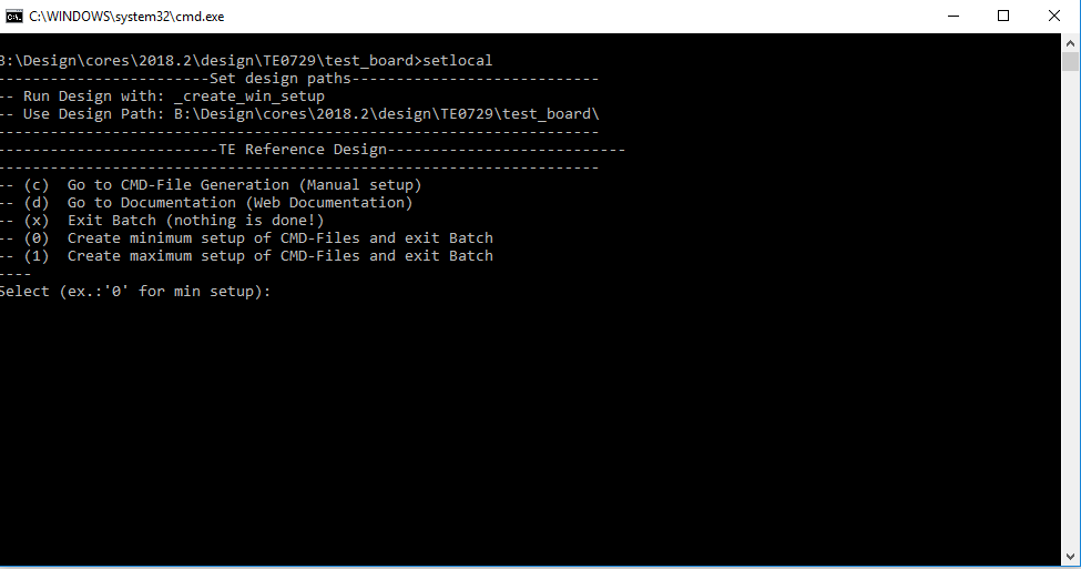
Run _create_win_setup.cmd/_create_linux_setup.sh and follow instructions on shell:
Code Block language bash theme Midnight title _create_win_setup.cmd/_create_linux_setup.sh ------------------------Set design paths---------------------------- -- Run Design with: _create_win_setup -- Use Design Path: <absolute project path> -------------------------------------------------------------------- -------------------------TE Reference Design--------------------------- -------------------------------------------------------------------- -- (0) Module selection guide, project creation...prebuilt export... -- (1) Create minimum setup of CMD-Files and exit Batch -- (2) Create maximum setup of CMD-Files and exit Batch -- (3) (internal only) Dev -- (4) (internal only) Prod -- (c) Go to CMD-File Generation (Manual setup) -- (d) Go to Documentation (Web Documentation) -- (g) Install Board Files from Xilinx Board Store (beta) -- (a) Start design with unsupported Vivado Version (beta) -- (x) Exit Batch (nothing is done!) ---- Select (ex.:'0' for module selection guide):- Press 0 and enter to start "Module Selection Guide"
- Createproject and follow instructions of the product selection guide, settings file will be configured automatically during this process.
optional for manual changes: Select correct device and Vitis install path on "design_basic_settings.cmd" and create Vivado project with "vivado_create_project_guimode.cmd"
Note Note: Select correct one, see also Vivado Board Part Flow
Create hardware description file (.xsa file) for PetaLinux project and export to prebuilt folder
Code Block language py theme Midnight title run on Vivado TCL (Script generates design and export files into "<project folder>\prebuilt\hardware\<short name>") TE::hw_build_design -export_prebuiltInfo Using Vivado GUI is the same, except file export to prebuilt folder.
- Create and configure your PetaLinux project with exported .xsa-file, see PetaLinux KICKstart
- use TE Template from "<project folder>\os\petalinux"
use exported .xsa file from "<project folder>\prebuilt\hardware\<short name>" . Note: HW Export from Vivado GUI creates another path as default workspace.
The build images are located in the "<plnx-proj-root>/images/linux" directory
(Optional) Configure the boot.scr file as needed, see Distro Boot with Boot.scr
- Generate Programming Files with Vitis (recommended)
- Copy PetaLinux build image files to prebuilt folder
copy u-boot.elf, system.dtb, image.ub and boot.scr from "<plnx-proj-root>/images/linux" to prebuilt folder
Info "<project folder>\prebuilt\os\petalinux\<ddr size>" or "<project folder>\prebuilt\os\petalinux\<short name>"
Page properties hidden true id Comments This step depends on Xilinx Device/Hardware
for Zynq-7000 series
- copy u-boot.elf, system.dtb, image.ub and boot.scr from "<plnx-proj-root>/images/linux" to prebuilt folder
for ZynqMP
- copy u-boot.elf, system.dtb, bl31.elf, image.ub and boot.scr from "<plnx-proj-root>/images/linux" to prebuilt folder
for Microblaze
- ...
- Generate Programming Files with Vitis
Code Block language py theme Midnight title run on Vivado TCL (Script generates applications and bootable files, which are defined in "test_board\sw_lib\apps_list.csv") TE::sw_run_vitis -all TE::sw_run_vitis (optional; Start Vitis from Vivado GUI or start with TE Scripts on Vivado TCL)Note TCL scripts generate also platform project, this must be done manually in case GUI is used. See Vitis
- Copy PetaLinux build image files to prebuilt folder
- Generate Programming Files with Petalinux (alternative), see PetaLinux KICKstart
Launch
| Scroll Ignore | ||||||||||||||
|---|---|---|---|---|---|---|---|---|---|---|---|---|---|---|
| ||||||||||||||
| Page properties | ||||
|---|---|---|---|---|
| ||||
Note:
|
Programming
| Note |
|---|
Check Module and Carrier TRMs for proper HW configuration before you try any design. |
AMD documentation for programming and debugging: Vivado/SDK/SDSoC-Xilinx Software Programming and Debugging
Get prebuilt boot binaries
- _create_win_setup.cmd/_create_linux_setup.sh and follow instructions on shell
- Press 0 and enter to start "Module Selection Guide"
- Select assembly version
- Validate selection
- Select Create and open delivery binary folder
Note: Folder (<project foler>/_binaries_<Artikel Name>) with subfolder (boot_<app name>) for different applications will be generated
QSPI-Boot mode
Option for Boot.bin on QSPI Flash and image.ub and boot.scr on SD.
- Connect JTAG and power on carrier with module
Open Vivado Project with "vivado_open_existing_project_guimode.cmd" or if not created, create with "vivado_create_project_guimode.cmd"
Code Block language py theme Midnight title run on Vivado TCL (Script programs BOOT.bin on QSPI flash) TE::pr_program_flash -swapp u-boot TE::pr_program_flash -swapp hello_te0820 (optional)- Copy image.ub and boot.scr on SD
- use files from "<project folder>\_binaries_<Article Name>\boot_linux" from generated binary folder,see: Get prebuilt boot binaries
- or use prebuilt file location, see "<project folder>\prebuilt\file_location.txt"
- Set Boot Mode to QSPI-Boot and insert SD
- Depends on Carrier, see carrier TRM.
- insert SD-Card.
SD-Boot mode
- Copy image.ub, boot.scr and Boot.bin on SD
- use files from "<project folder>\_binaries_<Article Name>\boot_linux" from generated binary folder, see: Get prebuilt boot binaries
- or use prebuilt file location, see "<project folder>\prebuilt\file_location.txt"
- Set Boot Mode to SD-Boot.
- Depends on Carrier, see carrier TRM.
- Insert SD-Card in SD-Slot.
JTAG
Not used on this Example.
Usage
- Prepare HW like described on section Programming
- Connect UART USB (most cases same as JTAG)
Select SD Card as Boot Mode (or QSPI - depending on step 1)
Info Note: See TRM of the Carrier, which is used.
Tip Starting with Petalinux version 2020.1, the industry standard "Distro-Boot" boot flow for U-Boot was introduced, which significantly expands the possibilities of the boot process and has the primary goal of making booting much more standardised and predictable.
The boot options described above describe the common boot processes for this hardware; other boot options are possible.
For more information see Distro Boot with Boot.scrPower On PCB
Expand title boot process 1. Zynq Boot ROM loads FSBL from SD/QSPI into OCM,
2. FSBL init PS, programs PL using the bitstream and loads U-boot from SD into DDR,
3. U-boot loads Linux (image.ub) from SD/QSPI/... into DDR
Page properties hidden true id Comments This step depends on Xilinx Device/Hardware
for Zynq-7000 series
1. Zynq Boot ROM loads FSBL from SD/QSPI into OCM,
2. FSBL init the PS, programs the PL using the bitstream and loads U-boot from SD/QSPI into DDR,
3. U-boot loads Linux (image.ub) from SD/QSPI/... into DDR
for ZynqMP???
1. ZynqMP Boot ROM loads FSBL from SD/QSPI into OCM,
2. FSBL init the PS, programs the PL using the bitstream and loads PMU, ATF and U-boot from SD/QSPI into DDR,
3. U-boot loads Linux (image.ub) from SD/QSPI/... into DDR
for Microblaze with Linux
1. FPGA Loads Bitfile from Flash,
2. MCS Firmware configure SI5338 and starts Microblaze, (only if mcs is available)
3. SREC Bootloader from Bitfile Firmware loads U-Boot into DDR (This takes a while),
4. U-boot loads Linux from QSPI Flash into DDR
for native FPGA
...
Linux
- Open Serial Console (e.g. putty)
- Speed: 115200
select COM Port
Info Win OS, see device manager, Linux OS see dmesg |grep tty (UART is *USB1)
Linux Console(not needed if autologin activated):
Code Block language bash theme Midnight # password disabled petalinux login: root Password: rootYou can use Linux shell now.
Code Block language bash theme Midnight i2cdetect -y -r 0 (check I2C 0 Bus) dmesg | grep rtc (RTC check) udhcpc (ETH0 check) lsusb (USB check)Optional Features
- Webserver to get access to Zynq
- insert IP on web browser to start web interface
- init.sh scripts
- add init.sh script on SD, content will be load automatically on startup (template included in "<project folder>\misc\SD")
- Webserver to get access to Zynq
Vivado HW Manager
| Page properties | ||||
|---|---|---|---|---|
| ||||
Note:
|
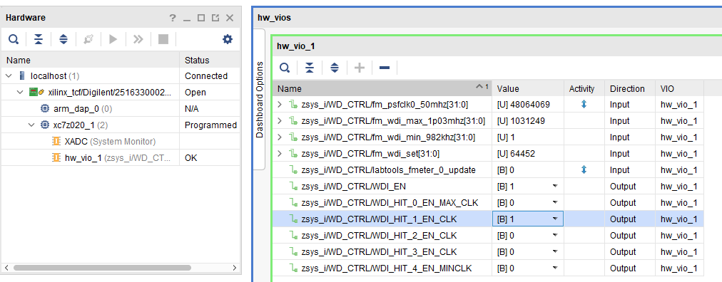
Open Vivado HW-Manager and add VIO signal to dashboard (*.ltx located on prebuilt folder)
- Control:
- "WDI_EN" and "WDI_HIT_*_EN_CLK" enables FPGA watchdog control.
- Force WD to system reboot:
- Check on Hardware window VIO status is ok. (right click on vio symbol and click "commit output values to VIO core" for update).
- Enable one of the "WDI_HIT_*_EN_CLK" signals
- Enable "WDI_EN"
- To force system to reboot, disable WDI_HIT clocks.
- Monitoring:
- Set radix for "fm_*" signals to unsigned integer to see frequ in Hz. PSFCLK0 50MHz was increased to 100MHz with version update 2023.2
- "fm_*" shows some clk frequencies (unit Hz). Note: inaccurate Reference CLK is used for frequency measurement.
| Scroll Title | ||||
|---|---|---|---|---|
| ||||
|

System Design - Vivado
| Scroll Ignore | ||||||||||||||
|---|---|---|---|---|---|---|---|---|---|---|---|---|---|---|
| ||||||||||||||
| Page properties | ||||
|---|---|---|---|---|
| ||||
Note:
|
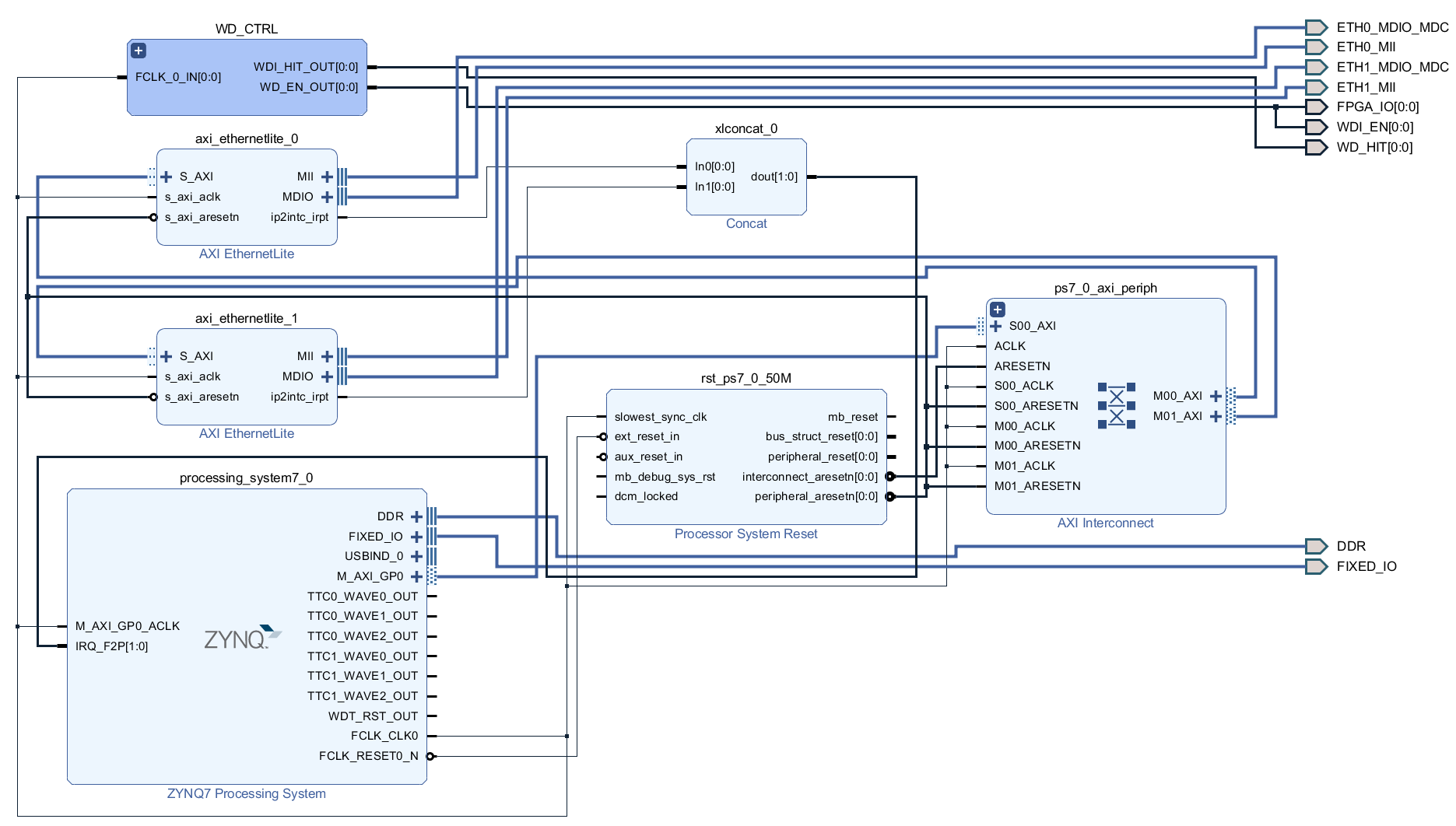
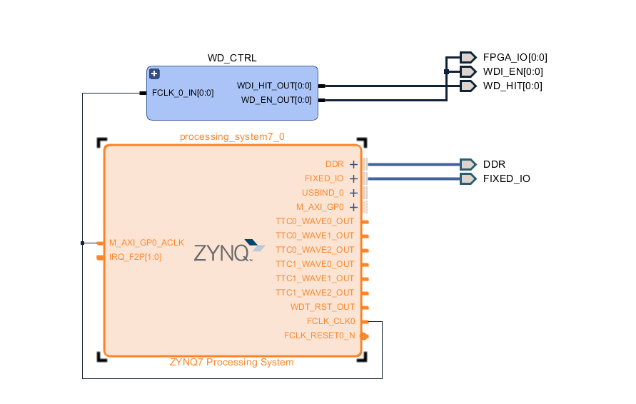
Block Design
| Scroll Title | ||||
|---|---|---|---|---|
| ||||
 |
PS Interfaces
| Scroll Title | ||||||||||||||||||||||||||||||||||||||||||||||
|---|---|---|---|---|---|---|---|---|---|---|---|---|---|---|---|---|---|---|---|---|---|---|---|---|---|---|---|---|---|---|---|---|---|---|---|---|---|---|---|---|---|---|---|---|---|---|
| ||||||||||||||||||||||||||||||||||||||||||||||
|
Constraints
Basic module constraints
| Code Block | ||||
|---|---|---|---|---|
| ||||
#
# Common bitgen related settings
#

set_property BITSTREAM.GENERAL.COMPRESS TRUE [current_design]
#set_property BITSTREAM.CONFIG.CONFIGRATE 66 [current_design]
set_property CONFIG_VOLTAGE 3.3 [current_design]
set_property CFGBVS VCCO [current_design]

set_property BITSTREAM.CONFIG.USR_ACCESS TIMESTAMP [current_design] |
| Code Block | ||||
|---|---|---|---|---|
| ||||
#
# Set unused pin pullup: PULLNONE, PULLUP, PULLDOWN
#

set_property BITSTREAM.CONFIG.UNUSEDPIN PULLNONE [current_design]

#set_property BITSTREAM.CONFIG.UNUSEDPIN PULLUP [current_design]
#set_property BITSTREAM.CONFIG.UNUSEDPIN PULLDONE [current_design] |
Design specific constraints
| Code Block | ||||
|---|---|---|---|---|
| ||||
set_property PACKAGE_PIN F16 [get_ports {FPGA_IO[0]}]
set_property IOSTANDARD LVCMOS33 [get_ports {FPGA_IO[0]}]
set_property PACKAGE_PIN H15 [get_ports {WDI_EN[0]}]
set_property IOSTANDARD LVCMOS25 [get_ports {WDI_EN[0]}]
set_property PACKAGE_PIN R15 [get_ports {WD_HIT[0]}]
set_property IOSTANDARD LVCMOS25 [get_ports {WD_HIT[0]}] |
Software Design - Vitis
| Scroll Ignore | ||||||||||||||
|---|---|---|---|---|---|---|---|---|---|---|---|---|---|---|
| ||||||||||||||
| Page properties | ||||
|---|---|---|---|---|
| ||||
Note:
|
For Vitis project creation, follow instructions from:
Application
| Page properties | ||||
|---|---|---|---|---|
| ||||
---------------------------------------------------------- FPGA Example scuMCS Firmware to configure SI5338 and Reset System. srec_spi_bootloaderTE modified 2019.2 SREC Bootloader to load app or second bootloader from flash into DDR Descriptions:
xilisf_v5_11TE modified 2019.2 xilisf_v5_11
---------------------------------------------------------- Zynq Example: zynq_fsblTE modified 2019.2 FSBL General:
Module Specific:
zynq_fsbl_flashTE modified 2019.2 FSBL General:
ZynqMP Example: ---------------------------------------------------------- zynqmp_fsblTE modified 2019.2 FSBL General:
Module Specific:
zynqmp_fsbl_flashTE modified 2019.2 FSBL General:
|
| HTML |
|---|
<!--
Template Revision 1.4.1
Basic Notes
 - export PDF to download, if vivado revision is changed!
 - Template is for different design and SDSoC and examples, remove unused or wrong description!
--> |
| Scroll Only (inline) |
|---|
Online version of this manual and other related documents can be found at https://wiki.trenz-electronic.de/display/PD/Trenz+Electronic+Documentation |
| Scroll pdf ignore | ||||
|---|---|---|---|---|
Table of contents
|
Overview
| HTML |
|---|
<!--
General Design description
--> |
TE0729 Basic-System with Watchdog example via VIO Interface.
Key Features
| HTML |
|---|
<!--
Add Basic Key Features of the design (should be tested)
--> |
| Excerpt |
|---|
|
Revision History
| HTML |
|---|
<!--
- Add changes from design
- Export PDF to download, if vivado revision is changed!
--> |
...
Release Notes and Know Issues
| HTML |
|---|
<!--
- add known Design issues and general Notes for the current revision
--> |
...
Requirements
Software
| HTML |
|---|
<!--
Add needed external Software
--> |
...
Hardware
| HTML |
|---|
<!--
Hardware Support
--> |
Basic description of TE Board Part Files is available on TE Board Part Files.
Complete List is available on <design name>/board_files/*_board_files.csv
Design supports following modules:
...
Design supports following carriers:
...
Additional HW Requirements:
...
Content
| HTML |
|---|
<!--
Remove unused content
--> |
For general structure and of the reference design, see Project Delivery - Xilinx devices
Design Sources
...
Additional Sources
...
Prebuilt
| HTML |
|---|
<!--

<table width="100%">
<tr> <th>File                                 </th> <th>File-Extension</th>  <th>Description                                                                              </th> </tr>
<tr> <td>BIF-File                             </td> <td>*.bif         </td>  <td>File with description to generate Bin-File                                               </td> </tr>
<tr> <td>BIN-File                             </td> <td>*.bin         </td>  <td>Flash Configuration File with Boot-Image (Zynq-FPGAs)                                    </td> </tr>
<tr> <td>BIT-File                             </td> <td>*.bit         </td>  <td>FPGA Configuration File                                                                  </td> </tr>
<tr> <td>DebugProbes-File                     </td> <td>*.ltx         </td>  <td>Definition File for Vivado/Vivado Labtools Debugging Interface                           </td> </tr>
<tr> <td>Debian SD-Image                      </td> <td>*.img         </td>  <td>Debian Image for SD-Card                                                                </td> </tr>
<tr> <td>Diverse Reports                      </td> <td>  ---         </td>  <td>Report files in different formats                                                        </td> </tr>
<tr> <td>Hardware-Platform-Specification-Files</td> <td>*.hdf         </td>  <td>Exported Vivado Hardware Specification for SDK/HSI                                       </td> </tr>
<tr> <td>LabTools Project-File                </td> <td>*.lpr         </td>  <td>Vivado Labtools Project File                                                             </td> </tr>
<tr> <td>MCS-File                             </td> <td>*.mcs         </td>  <td>Flash Configuration File with Boot-Image (MicroBlaze or FPGA part only)                  </td> </tr>
<tr> <td>MMI-File                             </td> <td>*.mmi         </td>  <td>File with BRAM-Location to generate MCS or BIT-File with *.elf content (MicroBlaze only) </td> </tr>
<tr> <td>OS-Image                             </td> <td>*.ub          </td>  <td>Image with Linux Kernel (On Petalinux optional with Devicetree and RAM-Disk)             </td> </tr>
<tr> <td>Software-Application-File            </td> <td>*.elf         </td>  <td>Software Application for Zynq or MicroBlaze Processor Systems                            </td> </tr>
<tr> <td>SREC-File                            </td> <td>*.srec        </td>  <td>Converted Software Application for MicroBlaze Processor Systems                          </td> </tr>
</table>
-->
|
...
File
...
File-Extension
...
Description
...
Download
Reference Design is only usable with the specified Vivado/SDK/PetaLinux/SDx version. Do never use different Versions of Xilinx Software for the same Project.
| HTML |
|---|
<!--
Add correct path:https://shop.trenz-electronic.de/en/Download/?path=Trenz_Electronic/TE0803/Reference_Design/2017.1/Starterkit
--> |
Reference Design is available on:
Design Flow
| HTML |
|---|
<!--
Basic Design Steps
Add/ Remove project specific
--> |
| Note |
|---|
Reference Design is available with and without prebuilt files. It's recommended to use TE prebuilt files for first lunch. |
Trenz Electronic provides a tcl based built environment based on Xilinx Design Flow.
See also:
The Trenz Electronic FPGA Reference Designs are TCL-script based project. Command files for execution will be generated with "_create_win_setup.cmd" on Windows OS and "_create_linux_setup.sh" on Linux OS.
TE Scripts are only needed to generate the vivado project, all other additional steps are optional and can also executed by Xilinx Vivado/SDK GUI. For currently Scripts limitations on Win and Linux OS see: Project Delivery Currently limitations of functionality
- _create_win_setup.cmd/_create_linux_setup.sh and follow instructions on shell:
- Press 0 and enter for minimum setup
- (optional Win OS) Generate Virtual Drive or use short directory for the reference design (for example x:\<design name>)
- Create Project
- Select correct device and Xilinx install path on "design_basic_settings.cmd" and create Vivado project with "vivado_create_project_guimode.cmd"
Note: Select correct one, see TE Board Part Files
- Select correct device and Xilinx install path on "design_basic_settings.cmd" and create Vivado project with "vivado_create_project_guimode.cmd"
- Create HDF and export to prebuilt folder
- Run on Vivado TCL: TE::hw_build_design -export_prebuilt
Note: Script generate design and export files into \prebuilt\hardware\<short dir>. Use GUI is the same, except file export to prebuilt folder
- Run on Vivado TCL: TE::hw_build_design -export_prebuilt
- Create Linux (uboot.elf and image.ub) with exported HDF
- HDF is exported to "prebuilt\hardware\<short name>"
Note: HW Export from Vivado GUI create another path as default workspace. - Create Linux images on VM, see PetaLinux KICKstart
- Use TE Template from /os/petalinux
Note: run init_config.sh before you start petalinux config. This will set correct temporary path variable.
- Use TE Template from /os/petalinux
- HDF is exported to "prebuilt\hardware\<short name>"
- Add Linux files (uboot.elf and image.ub) to prebuilt folder
- "prebuilt\os\petalinux\default" or "prebuilt\os\petalinux\<short name>"
Notes: Scripts select "prebuilt\os\petalinux\<short name>", if exist, otherwise "prebuilt\os\petalinux\default"
- "prebuilt\os\petalinux\default" or "prebuilt\os\petalinux\<short name>"
- Generate Programming Files with HSI/SDK
- Run on Vivado TCL: TE::sw_run_hsi
Note: Scripts generate applications and bootable files, which are defined in "sw_lib\apps_list.csv" - (alternative) Start SDK with Vivado GUI or start with TE Scripts on Vivado TCL: TE::sw_run_sdk
Note: See SDK Projects
- Run on Vivado TCL: TE::sw_run_hsi
Launch
Programming
| HTML |
|---|
<!--
Description of Block Design, Constrains...
BD Pictures from Export...
--> |
| Note |
|---|
Check Module and Carrier TRMs for proper HW configuration before you try any design. |
Xilinx documentation for programming and debugging: Vivado/SDK/SDSoC-Xilinx Software Programming and Debugging
QSPI
Optional for Boot.bin on QSPI Flash and image.ub on SD.
- Connect JTAG and power on carrier with module
- Open Vivado Project with "vivado_open_existing_project_guimode.cmd" or if not created, create with "vivado_create_project_guimode.cmd"
- Type on Vivado TCL Console: TE::pr_program_flash_binfile -swapp u-boot
Note: To program with SDK/Vivado GUI, use special FSBL (zynqmp_fsbl_flash) on setup
optional "TE::pr_program_flash_binfile -swapp hello_te0729" possible - Copy image.ub on SD-Card
- For correct prebuilt file location, see <design_name>/prebuilt/readme_file_location.txt
- Insert SD-Card
SD
- Copy image.ub and Boot.bin on SD-Card.
- For correct prebuilt file location, see <design_name>/prebuilt/readme_file_location.txt
- Set Boot Mode to SD-Boot.
- Depends on Carrier, see carrier TRM.
- Insert SD-Card in SD-Slot.
JTAG
Not used on this Example.
Usage
- Prepare HW like described on section Programming
- Connect UART USB (most cases same as JTAG)
- Select SD Card as Boot Mode
Note: See TRM of the Carrier, which is used. - Power On PCB
Note: 1. Zynq Boot ROM loads FSBL from SD into OCM, 2. FSBL loads U-boot from SD into DDR, 3. U-boot load Linux from SD into DDR
Linux
- Open Serial Console (e.g. putty)
- Speed: 115200
- COM Port: Win OS, see device manager, Linux OS see dmesg |grep tty (UART is *USB1)
- Linux Console:
Note: Wait until Linux boot finished For Linux Login use:- User Name: root
- Password: root
- You can use Linux shell now.
- I2C 0 Bus type: i2cdetect -y -r 0
- I2C 0 Bus type: i2cdetect -y -r 1
- ETH0 works with udhcpc
- ETH1 must be configured manually
- ifconfig eth1 up
- ifconfig eth1 <ip>
- ETH1 must be configured manually
- ifconfig eth1 up
- ifconfig eth1 <ip>
- RTC check: dmesg | grep rtc
- USB: insert USB Stick or lsusb
...
- Open Vivado Hardware Manager with auto connect.
- Use probe specification (*.ltx) from prebuilt folder.
- Add VIO signals to dashboard.
- Set radix for "fm_*" signals to unsigned integer.
- "fm_*" shows some clk frequencies (unit Hz). Note: inaccurate Reference CLK is used for frequency measurement.
- "WDI_EN" and "WDI_HIT_*_EN_CLK" enables FPGA watchdog control.
- Force WD to system reboot:
- Check on Hardware window VIO status is ok. (right click on vio symbol and click "commit output values to VIO core" for update).
- Enable one of the "WDI_HIT_*_EN_CLK" signals
- Enable "WDI_EN"
- To force system to reboot, disable WDI_HIT clocks.
System Design - Vivado
| HTML |
|---|
<!--
Description of Block Design, Constrains...
BD Pictures from Export...
--> |
Block Design
R Variant:
PS Interfaces
...
Constrains
Basic module constrains
| Code Block | ||||
|---|---|---|---|---|
| ||||
#
# Common bitgen related settings
#

set_property BITSTREAM.GENERAL.COMPRESS TRUE [current_design]
#set_property BITSTREAM.CONFIG.CONFIGRATE 66 [current_design]
set_property CONFIG_VOLTAGE 3.3 [current_design]
set_property CFGBVS VCCO [current_design]

set_property BITSTREAM.CONFIG.USR_ACCESS TIMESTAMP [current_design] |
| Code Block | ||||
|---|---|---|---|---|
| ||||
#
# Set unused pin pullup: PULLNONE, PULLUP, PULLDOWN
#

set_property BITSTREAM.CONFIG.UNUSEDPIN PULLNONE [current_design]

#set_property BITSTREAM.CONFIG.UNUSEDPIN PULLUP [current_design]
#set_property BITSTREAM.CONFIG.UNUSEDPIN PULLDONE [current_design] |
Design specific constrain
| Code Block | ||||
|---|---|---|---|---|
| ||||
set_property PACKAGE_PIN F16 [get_ports {FPGA_IO[0]}]
set_property IOSTANDARD LVCMOS33 [get_ports {FPGA_IO[0]}]
set_property PACKAGE_PIN H15 [get_ports {WDI_EN[0]}]
set_property IOSTANDARD LVCMOS25 [get_ports {WDI_EN[0]}]
set_property PACKAGE_PIN R15 [get_ports {WD_HIT[0]}]
set_property IOSTANDARD LVCMOS25 [get_ports {WD_HIT[0]}] |
Software Design - SDK/HSI
| HTML |
|---|
<!--
optional chapter
separate sections for different apps
--> |
For SDK project creation, follow instructions from:
Application
Source location: \sw_lib\sw_apps
zynqmp_fsbl
TE modified 2018.2 FSBL. Xilinx default FSBL on default setup. eMMC selection with FSBL possible.
Changes:
- Optional define for eMMC selection with FSBL (default SD selected)
- uncomment #define USE_EMMC on fsbl_hooks.c to select eMMC instead of SD
- See: fsbl_hooks.c, main.c
zynqmp_fsbl_flash
TE modified 2018.2 FSBL
...
...
...
Hello TE0729 is a Xilinx Hello World example as endless loop instead of one console output.
u-boot
U-Boot.elf is generated with PetaLinux. SDK/HSI is used to generate Boot.bin.
Software Design - PetaLinux
| HTML |
|---|
<!--
optional chapter
Add "No changes." or "Activate: and add List"
--> |
For PetaLinux installation and project creation, follow instructions from:
Config
No changes.
U-Boot
Change platform-top.h
| Code Block | ||
|---|---|---|
| ||
#include <configs/platform-auto.h>
#define CONFIG_SYS_BOOTM_LEN 0xF000000
#define DFU_ALT_INFO_RAM \
                "dfu_ram_info=" \
        "setenv dfu_alt_info " \
        "image.ub ram $netstart 0x1e00000\0" \
        "dfu_ram=run dfu_ram_info && dfu 0 ram 0\0" \
        "thor_ram=run dfu_ram_info && thordown 0 ram 0\0"

#define DFU_ALT_INFO_MMC \
        "dfu_mmc_info=" \
        "set dfu_alt_info " \
        "${kernel_image} fat 0 1\\\\;" \
        "dfu_mmc=run dfu_mmc_info && dfu 0 mmc 0\0" \
        "thor_mmc=run dfu_mmc_info && thordown 0 mmc 0\0"


/*Required for uartless designs */
#ifndef CONFIG_BAUDRATE
#define CONFIG_BAUDRATE 115200
#ifdef CONFIG_DEBUG_UART
#undef CONFIG_DEBUG_UART
#endif
#endif

/*Define CONFIG_ZYNQ_EEPROM here and its necessaries in u-boot menuconfig if you had EEPROM memory. */
#ifdef CONFIG_ZYNQ_EEPROM
#define CONFIG_SYS_I2C_EEPROM_ADDR_LEN         1
#define CONFIG_SYS_I2C_EEPROM_ADDR             0x54
#define CONFIG_SYS_EEPROM_PAGE_WRITE_BITS      4
#define CONFIG_SYS_EEPROM_PAGE_WRITE_DELAY_MS  5
#define CONFIG_SYS_EEPROM_SIZE                 1024 /* Bytes */
#define CONFIG_SYS_I2C_MUX_ADDR                0x74
#define CONFIG_SYS_I2C_MUX_EEPROM_SEL          0x4
#endif |
Device Tree
Note: for R assembly variant, remove ETH1, ETH2 and RTC
...
...
...
...
...
...
...
...
...
...
...
...
...
Kernel
Activate:
- RTC_DRV_ISL12022 (Not needed for R assembly variant, remove)
Rootfs
Activate:
- i2c-tools
Applications
...
...
...
Additional Software
| HTML |
|---|
<!--
Add Description for other Software, for example SI CLK Builder ...
--> |
No additional software is needed.
...
...
...
...
...
...
...
...
...
...
...
...
...
Overview
Content Tools