Page History
...
| Excerpt |
|---|
|
...
| Scroll Title | ||||||||||||||||||||||||||||||
|---|---|---|---|---|---|---|---|---|---|---|---|---|---|---|---|---|---|---|---|---|---|---|---|---|---|---|---|---|---|---|
| ||||||||||||||||||||||||||||||
|
Release Notes and Know Issues
...
| Scroll Title | |||||||||||||||||||||||||||||
|---|---|---|---|---|---|---|---|---|---|---|---|---|---|---|---|---|---|---|---|---|---|---|---|---|---|---|---|---|---|
| |||||||||||||||||||||||||||||
|
Hardware
| Page properties | ||||
|---|---|---|---|---|
| ||||
Notes :
|
...
| Scroll Title | ||||||||||||||||||||||||||||||||||
|---|---|---|---|---|---|---|---|---|---|---|---|---|---|---|---|---|---|---|---|---|---|---|---|---|---|---|---|---|---|---|---|---|---|---|
| ||||||||||||||||||||||||||||||||||
|
Design supports following carriers:
| Scroll Title | ||||||||||||||||||||||
|---|---|---|---|---|---|---|---|---|---|---|---|---|---|---|---|---|---|---|---|---|---|---|
| ||||||||||||||||||||||
|
Additional HW Requirements:
| Scroll Title | ||||||||||||||||||||
|---|---|---|---|---|---|---|---|---|---|---|---|---|---|---|---|---|---|---|---|---|
| ||||||||||||||||||||
|
Content
|
Content
| Page properties | ||||
|---|---|---|---|---|
| ||||
Notes :
|
...
| Scroll Title | ||||||||||||||||||||||||||||||
|---|---|---|---|---|---|---|---|---|---|---|---|---|---|---|---|---|---|---|---|---|---|---|---|---|---|---|---|---|---|---|
| ||||||||||||||||||||||||||||||
|
Prebuilt
| Page properties | ||||||||||||||||||||||||||||||||||||||||||||||||||||||||||||||||||||||
|---|---|---|---|---|---|---|---|---|---|---|---|---|---|---|---|---|---|---|---|---|---|---|---|---|---|---|---|---|---|---|---|---|---|---|---|---|---|---|---|---|---|---|---|---|---|---|---|---|---|---|---|---|---|---|---|---|---|---|---|---|---|---|---|---|---|---|---|---|---|---|
| ||||||||||||||||||||||||||||||||||||||||||||||||||||||||||||||||||||||
Notes :
|
| Scroll Title | |||||||||||||||||||||||||||||||||||||||||||||||||||||||||||||||
|---|---|---|---|---|---|---|---|---|---|---|---|---|---|---|---|---|---|---|---|---|---|---|---|---|---|---|---|---|---|---|---|---|---|---|---|---|---|---|---|---|---|---|---|---|---|---|---|---|---|---|---|---|---|---|---|---|---|---|---|---|---|---|---|
| |||||||||||||||||||||||||||||||||||||||||||||||||||||||||||||||
|
Download
Reference Design is only usable with the specified Vivado/Vitis/PetaLinux version. Do never use different Versions of Xilinx Software for the same Project.
...
Reference Design is available on:
Design Flow
| Page properties | ||||
|---|---|---|---|---|
| ||||
Notes :
|
| Note |
|---|
Reference Design is available with and without prebuilt files. It's recommended to use TE prebuilt files for first lunch. |
Trenz Electronic provides a tcl based built environment based on Xilinx Design Flow.
See also:
- Xilinx Development Tools#XilinxSoftware-BasicUserGuides
- Vivado Projects - TE Reference Design
- Project Delivery.
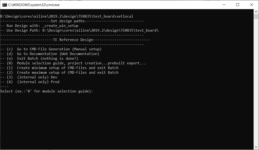
The Trenz Electronic FPGA Reference Designs are TCL-script based project. Command files for execution will be generated with "_create_win_setup.cmd" on Windows OS and "_create_linux_setup.sh" on Linux OS.
TE Scripts are only needed to generate the vivado project, all other additional steps are optional and can also executed by Xilinx Vivado/SDK GUI. For currently Scripts limitations on Win and Linux OS see: Project Delivery Currently limitations of functionality
- _create_win_setup.cmd/_create_linux_setup.sh and follow instructions on shell:
- Press 0 and enter to start "Module Selection Guide"
- (optional Win OS) Generate Virtual Drive or use short directory for the reference design (for example x:\<design name>)
- Create Project (follow instruction of the product selection guide), settings file will be configured automatically during this process)
- (optional for manual changes) Select correct device and Xilinx install path on "design_basic_settings.cmd" and create Vivado project with "vivado_create_project_guimode.cmd"
Note: Select correct one, see alsoTE Board Part Files
- (optional for manual changes) Select correct device and Xilinx install path on "design_basic_settings.cmd" and create Vivado project with "vivado_create_project_guimode.cmd"
- Create XSA and export to prebuilt folder
- Run on Vivado TCL: TE::hw_build_design -export_prebuilt
Note: Script generate design and export files into \prebuilt\hardware\<short dir>. Use GUI is the same, except file export to prebuilt folder
- Run on Vivado TCL: TE::hw_build_design -export_prebuilt
- Create Linux (uboot.elf and image.ub) with exported XSA
- XSA is exported to "prebuilt\hardware\<short name>"
Note: HW Export from Vivado GUI create another path as default workspace. - Create Linux images on VM, see PetaLinux KICKstart
- Use TE Template from /os/petalinux
- XSA is exported to "prebuilt\hardware\<short name>"
- Add Linux files (uboot.elf and image.ub) to prebuilt folder
- "prebuilt\os\petalinux\<ddr size>" or "prebuilt\os\petalinux\<short name>"
- Generate Programming Files with Vitis
- Run on Vivado TCL: TE::sw_run_vitis -all
Note: Scripts generate applications and bootable files, which are defined in "sw_lib\apps_list.csv" - (alternative) Start SDK with Vivado GUI or start with TE Scripts on Vivado TCL: TE::sw_run_vitis
Note: TCL scripts generate also platform project, this must be done manuelly in case GUI is used. See Vitis
- Run on Vivado TCL: TE::sw_run_vitis -all
Launch
| Page properties | ||||
|---|---|---|---|---|
| ||||
Note:
|
Programming
| Note |
|---|
Check Module and Carrier TRMs for proper HW configuration before you try any design. |
Xilinx documentation for programming and debugging: Vivado/SDK/SDSoC-Xilinx Software Programming and Debugging
Get prebuilt boot binaries
- _create_win_setup.cmd/_create_linux_setup.sh and follow instructions on shell
- Press 0 and enter to start "Module Selection Guide"
- Select assembly version
- Validate selection
- Select Create and open delivery binary folder
Note: Folder (<project foler>/_binaries_<Artikel Name>) with subfolder (boot_<app name>) for different applications will be generated
QSPI
Optional for Boot.bin on QSPI Flash and image.ub on SD.
- Connect JTAG and power on carrier with module
- Open Vivado Project with "vivado_open_existing_project_guimode.cmd" or if not created, create with "vivado_create_project_guimode.cmd"
- Type on Vivado TCL Console: TE::pr_program_flash -swapp u-boot
Note: To program with SDK/Vivado GUI, use special FSBL (zynqmp_fsbl_flash) on setup
optional "TE::pr_program_flash -swapp hello_te0820" possible - Copy image.ub on SD-Card
- use files from (<project foler>/_binaries_<Articel Name>)/boot_linux from generated binary folder,see: Get prebuilt boot binaries
- or use prebuilt file location, see <design_name>/prebuilt/readme_file_location.txt
- Insert SD-Card
SD
- Copy image.ub and Boot.bin on SD-Card
- use files from (<project foler>/_binaries_<Articel Name>)/boot_linux from generated binary folder,see: Get prebuilt boot binaries
- or use prebuilt file location, see <design_name>/prebuilt/readme_file_location.txt
- Set Boot Mode to SD-Boot.
- Depends on Carrier, see carrier TRM.
- Insert SD-Card in SD-Slot.
JTAG
Not used on this Example.
Usage
- Prepare HW like described on section 43680037
- Connect UART USB (most cases same as JTAG)
- Select SD Card as Boot Mode (or QSPI - depending on step 1)
Note: See TRM of the Carrier, which is used. - Power On PCB
Note: 1. Zynq Boot ROM loads FSBL from SD into OCM, 2. FSBL loads U-boot from SD into DDR, 3. U-boot load Linux from SD into DDR
Linux
- Open Serial Console (e.g. putty)
- Speed: 115200
- COM Port: Win OS, see device manager, Linux OS see dmesg |grep tty (UART is *USB1)
- Linux Console:
Note: Wait until Linux boot finished For Linux Login use:- User Name: root
- Password: root
- You can use Linux shell now.
- I2C 0 Bus type: i2cdetect -y -r 0
- RTC check: dmesg | grep rtc
- ETH0 works with udhcpc
- USB type "lsusb" or connect USB2.0 device
- Option Features
- Webserver to get access to Zynq
- insert IP on web browser to start web interface
- init.sh scripts
- add init.sh script on SD, content will be load automatically on startup (template included in ./misc/SD)
- add init.sh script on SD, content will be load automatically on startup (template included in ./misc/SD)
- Webserver to get access to Zynq
Vivado HW Manager
| Page properties | ||||
|---|---|---|---|---|
| ||||
Note:
|
Open Vivado HW-Manager and add VIO signal to dashboard (*.ltx located on prebuilt folder)
- Control:
- Monitoring:
...
| anchor | Figure_VHM |
|---|---|
| title | Vivado Hardware Manager |
System Design - Vivado
| Page properties | ||||
|---|---|---|---|---|
| ||||
Note:
|
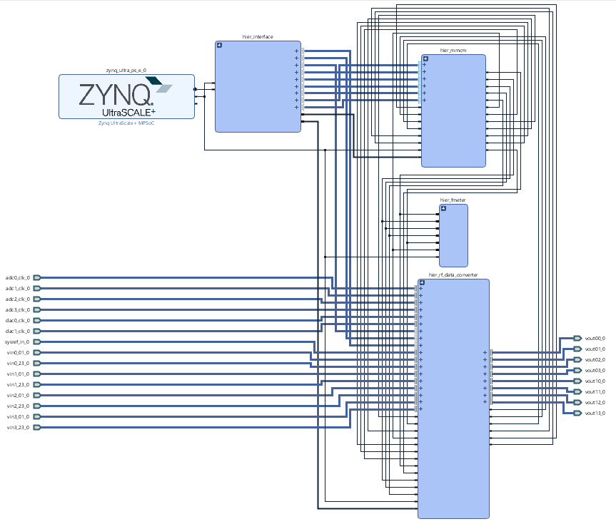
Block Design
...
| anchor | Figure_BD |
|---|---|
| title | Block Design |
PS Interfaces
| Page properties | ||||
|---|---|---|---|---|
| ||||
Note:
|
Activated interfaces:
...
| anchor | Table_PSI |
|---|---|
| title | PS Interfaces |
...
Constrains
Basic module constrains
| Code Block | ||||
|---|---|---|---|---|
| ||||
set_property BITSTREAM.GENERAL.COMPRESS TRUE [current_design]
set_property CONFIG_VOLTAGE 3.3 [current_design]
set_property CFGBVS VCCO [current_design]

set_property BITSTREAM.CONFIG.USR_ACCESS TIMESTAMP [current_design] |
Design specific constrain
| Code Block | ||||
|---|---|---|---|---|
| ||||
set_property PACKAGE_PIN K2 [get_ports {fclk[0]}]
set_property IOSTANDARD LVCMOS18 [get_ports {fclk[0]}]
set_property CLOCK_DEDICATED_ROUTE FALSE [get_nets fclk_IBUF[0]] |
Software Design - Vitis
| Page properties | ||||
|---|---|---|---|---|
| ||||
Note:
|
For SDK project creation, follow instructions from:
Application
...
| hidden | true |
|---|---|
| id | Comments |
----------------------------------------------------------
FPGA Example
scu
MCS Firmware to configure SI5338 and Reset System.
srec_spi_bootloader
TE modified 2019.2 SREC
Bootloader to load app or second bootloader from flash into DDR
Descriptions:
- Modified Files: blconfig.h, bootloader.c
- Changes:
- Add some console outputs and changed bootloader read address.
- Add bugfix for 2018.2 qspi flash
xilisf_v5_11
TE modified 2019.2 xilisf_v5_11
- Changed default Flash type to 5.
----------------------------------------------------------
Zynq Example:
zynq_fsbl
TE modified 2019.2 FSBL
General:
- Modified Files:main.c, fsbl_hooks.h/.c (search for 'TE Mod' on source code)
Add Files: te_fsbl_hooks.h/.c(for hooks and board)\n\
- General Changes:
- Display FSBL Banner and Device ID
Module Specific:
- Add Files: all TE Files start with te_*
- READ MAC from EEPROM and make Address accessible by UBOOT (need copy defines on uboot platform-top.h)
- CPLD access
- Read CPLD Firmware and SoC Type
- Configure Marvell PHY
zynq_fsbl_flash
TE modified 2019.2 FSBL
General:
- Modified Files: main.c
- General Changes:
- Display FSBL Banner
- Set FSBL Boot Mode to JTAG
- Disable Memory initialisation
ZynqMP Example:
----------------------------------------------------------
zynqmp_fsbl
TE modified 2019.2 FSBL
General:
- Modified Files: xfsbl_main.c, xfsbl_hooks.h/.c, xfsbl_board.h/.c(search for 'TE Mod' on source code)
- Add Files: te_xfsbl_hooks.h/.c (for hooks and board)\n\
- General Changes:
- Display FSBL Banner and Device Name
Module Specific:
- Add Files: all TE Files start with te_*
- Si5338 Configuration
- ETH+OTG Reset over MIO
zynqmp_fsbl_flash
TE modified 2019.2 FSBL
General:
- Modified Files: xfsbl_initialisation.c, xfsbl_hw.h, xfsbl_handoff.c, xfsbl_main.c
- General Changes:
- Display FSBL Banner
- Set FSBL Boot Mode to JTAG
- Disable Memory initialisation
zynqmp_pmufw
Xilinx default PMU firmware.
----------------------------------------------------------
General Example:
hello_te0820
Hello TE0820 is a Xilinx Hello World example as endless loop instead of one console output.
u-boot
U-Boot.elf is generated with PetaLinux. Vitis is used to generate Boot.bin.
Software Setup
Download RF Analyzer GUI from the following link and install it.
Hardware Setup
The Hardware contains of a TE0835 module and TEB0835 carrier board and has 8 ADC inputs and 8 DAC outputs.
- Plug the TE0835 module on the TEB0835 carrier board
- Connect the micro USB cable to the J29 connector
- Plug the power supply cable to the J19 connector
- Plug the prepared SD card on the SD card socket (J28)
- Connect a cable with SMA or SMT connector to one of the DAC connector( for example DAC0 J9) and feed it back to the related ADC input (for example ADC0 J1)
- (optional) A signal generator can be used to feed desired sinal to ADC input.
- (optional) An oscilloscope can be used to monitor the output signal of DAC.
| Designator | PIN | ADC/DAC Tile | Footprint |
|---|---|---|---|
| J1 | ADC0_IN | 224 ADC0 | SMA |
| J2 | ADC1_IN | 224 ADC1 | SMT |
| J3 | ADC2_IN | 225 ADC0 | SMA |
| J4 | ADC3_IN | 225 ADC1 | SMT |
| J5 | ADC4_IN | 226 ADC0 | SMA |
| J6 | ADC5_IN | 226 ADC1 | SMT |
| J7 | ADC6_IN | 227 ADC0 | SMA |
| J8 | ADC7_IN | 227 ADC1 | SMT |
| J9 | DAC0_OUT | 228 Pair0,1 | SMA |
| J10 | DAC1_OUT | 228 Pair0,1 | SMT |
| J11 | DAC2_OUT | 228 Pair2,3 | SMA |
| J12 | DAC3_OUT | 228 Pair2,3 | SMT |
| J13 | DAC4_OUT | 229 Pair0,1 | SMT |
| J14 | DAC5_OUT | 229 Pair0,1 | SMT |
| J15 | DAC6_OUT | 229 Pair2,3 | SMT |
| J16 | DAC7_OUT | 228 Pair2,3 | SMT |
| draw.io Diagram | ||||||||||||||||||||
|---|---|---|---|---|---|---|---|---|---|---|---|---|---|---|---|---|---|---|---|---|
|
Design Flow
| Page properties | ||||
|---|---|---|---|---|
| ||||
Notes :
|
| Note |
|---|
Reference Design is available with and without prebuilt files. It's recommended to use TE prebuilt files for first lunch. |
Trenz Electronic provides a tcl based built environment based on Xilinx Design Flow.
See also:
- Xilinx Development Tools#XilinxSoftware-BasicUserGuides
- Vivado Projects - TE Reference Design
- Project Delivery.
The Trenz Electronic FPGA Reference Designs are TCL-script based project. Command files for execution will be generated with "_create_win_setup.cmd" on Windows OS and "_create_linux_setup.sh" on Linux OS.
TE Scripts are only needed to generate the vivado project, all other additional steps are optional and can also executed by Xilinx Vivado/SDK GUI. For currently Scripts limitations on Win and Linux OS see: Project Delivery Currently limitations of functionality
- _create_win_setup.cmd/_create_linux_setup.sh and follow instructions on shell:
- Press 0 and enter to start "Module Selection Guide"
- (optional Win OS) Generate Virtual Drive or use short directory for the reference design (for example x:\<design name>)
- Create Project (follow instruction of the product selection guide), settings file will be configured automatically during this process)
- (optional for manual changes) Select correct device and Xilinx install path on "design_basic_settings.cmd" and create Vivado project with "vivado_create_project_guimode.cmd"
Note: Select correct one, see alsoTE Board Part Files
- (optional for manual changes) Select correct device and Xilinx install path on "design_basic_settings.cmd" and create Vivado project with "vivado_create_project_guimode.cmd"
- Create XSA and export to prebuilt folder
- Run on Vivado TCL: TE::hw_build_design -export_prebuilt
Note: Script generate design and export files into \prebuilt\hardware\<short dir>. Use GUI is the same, except file export to prebuilt folder
- Run on Vivado TCL: TE::hw_build_design -export_prebuilt
- Create Linux (bl31.elf, uboot.elf and image.ub) with exported XSA
- XSA is exported to "prebuilt\hardware\<short name>"
Note: HW Export from Vivado GUI create another path as default workspace. - Create Linux images on VM, see PetaLinux KICKstart
- Use TE Template from /os/petalinux
- XSA is exported to "prebuilt\hardware\<short name>"
- Add Linux files (bl31.elf, uboot.elf and image.ub) to prebuilt folder
- "prebuilt\os\petalinux\<ddr size>" or "prebuilt\os\petalinux\<short name>"
- Generate Programming Files with Vitis
- Run on Vivado TCL: TE::sw_run_vitis -all
Note: Scripts generate applications and bootable files, which are defined in "sw_lib\apps_list.csv" - (alternative) Start SDK with Vivado GUI or start with TE Scripts on Vivado TCL: TE::sw_run_vitis
Note: TCL scripts generate also platform project, this must be done manuelly in case GUI is used. See Vitis
- Run on Vivado TCL: TE::sw_run_vitis -all
Launch
| Page properties | ||||
|---|---|---|---|---|
| ||||
Note:
|
Programming
| Note |
|---|
Check Module and Carrier TRMs for proper HW configuration before you try any design. |
Xilinx documentation for programming and debugging: Vivado/SDK/SDSoC-Xilinx Software Programming and Debugging
Get prebuilt boot binaries
- _create_win_setup.cmd/_create_linux_setup.sh and follow instructions on shell
- Press 0 and enter to start "Module Selection Guide"
- Select assembly version
- Validate selection
- Select Create and open delivery binary folder
Note: Folder (<project foler>/_binaries_<Artikel Name>) with subfolder (boot_<app name>) for different applications will be generated
QSPI
Optional for Boot.bin on QSPI Flash and image.ub on SD.
- Connect JTAG and power on carrier with module
- Open Vivado Project with "vivado_open_existing_project_guimode.cmd" or if not created, create with "vivado_create_project_guimode.cmd"
- Type on Vivado TCL Console: TE::pr_program_flash -swapp u-boot
Note: To program with SDK/Vivado GUI, use special FSBL (zynqmp_fsbl_flash) on setup
optional "TE::pr_program_flash -swapp hello_te0835" possible - Copy image.ub on SD-Card
- use files from (<project foler>/_binaries_<Articel Name>)/boot_linux from generated binary folder,see: Get prebuilt boot binaries
- or use prebuilt file location, see <design_name>/prebuilt/readme_file_location.txt
- Insert SD-Card
SD
- Copy image.ub and Boot.bin on SD-Card
- use files from (<project foler>/_binaries_<Articel Name>)/boot_linux from generated binary folder,see: Get prebuilt boot binaries
- or use prebuilt file location, see <design_name>/prebuilt/readme_file_location.txt
- Set Boot Mode to SD-Boot.
- Depends on Carrier, see carrier TRM.
- Insert SD-Card in SD-Slot.
JTAG
Not used on this Example.
Usage
- Prepare HW like described on section TE0835 Test Board#Programming
- Connect UART USB (most cases same as JTAG)
- Select SD Card as Boot Mode (or QSPI - depending on step 1)
Note: See TRM of the Carrier, which is used. - Power On PCB
Note: 1. Zynqmp Boot ROM loads FSBL from SD into OCM, 2. FSBL loads U-boot from SD into DDR, 3. U-boot load Linux from SD into DDR - Open the RF Analyzer GUI
- Click on Connect
- Adjust the desired JTAG frequency
- Give the bitstream file path
- Click on Download Bitstream on the FPGA
- When is the downloading finished, click on Select Target
- After the initilalisation, all ADCs/DACs tile are visible
- Click the desired DAC tile and choose a DAC (for example DAC0)
- Adjust the desired DAC property (for example output frequency)
- Click on Generation to generate the signal in output of DAC
- Click the related ADC tile and choose the related ADC (for example ADC0)
- Click on Acquisition to aqcuire the input signal
- The spectum of the DAC output signal can be seen now. The signal can be visible in time domain too.
Linux
- Open Serial Console (e.g. putty)
- Speed: 115200
- COM Port: Win OS, see device manager, Linux OS see dmesg |grep tty (UART is *USB1)
- Linux Console:
Note: Wait until Linux boot finished For Linux Login use:- User Name: root
- Password: root
- You can use Linux shell now.
- I2C 0 Bus type: i2cdetect -y -r 0
- I2C 1 Bus type: i2cdetect -y -r 1
- RTC check: dmesg | grep rtc
- ETH0 works with udhcpc
- USB type "lsusb" or connect USB2.0 device
- Option Features
- Webserver to get access to Zynqmp
- insert IP on web browser to start web interface
- init.sh scripts
- add init.sh script on SD, content will be load automatically on startup (template included in ./misc/SD)
- add init.sh script on SD, content will be load automatically on startup (template included in ./misc/SD)
- Webserver to get access to Zynqmp
Vivado HW Manager
| Page properties | ||||
|---|---|---|---|---|
| ||||
Note:
|
Open Vivado HW-Manager and add VIO signal to dashboard (*.ltx located on prebuilt folder)
- Monitoring:
- The output frequency of MMCM blocks can be monitored.
- Set radix from VIO signals to unsigned integer.
- The tempreature of ARM processor and FPGA can be measured too.
- The output frequency of MMCM blocks can be monitored.
| Scroll Title | ||||
|---|---|---|---|---|
| ||||
System Design - Vivado
| Page properties | ||||
|---|---|---|---|---|
| ||||
Note:
|
Block Design
| Scroll Title | ||||
|---|---|---|---|---|
| ||||
 |
PS Interfaces
| Page properties | ||||
|---|---|---|---|---|
| ||||
Note:
|
Activated interfaces:
| Scroll Title | ||||||||||||||||||||||||||||||||||||||||||||||||
|---|---|---|---|---|---|---|---|---|---|---|---|---|---|---|---|---|---|---|---|---|---|---|---|---|---|---|---|---|---|---|---|---|---|---|---|---|---|---|---|---|---|---|---|---|---|---|---|---|
| ||||||||||||||||||||||||||||||||||||||||||||||||
|
Constrains
Basic module constrains
| Code Block | ||||
|---|---|---|---|---|
| ||||
set_property BITSTREAM.GENERAL.COMPRESS TRUE [current_design]
set_property BITSTREAM.CONFIG.UNUSEDPIN PULLNONE [current_design] |
Design specific constrain
| Code Block | ||||
|---|---|---|---|---|
| ||||
set_false_path -from [get_pins -hier -filter {name=~*labtools_fmeter_0/U0/*/CLK}] -to [get_pins -hier -filter {name=~*labtools_fmeter_0/U0/F_reg[*]/D}]
set_false_path -from [get_pins -hier -filter {name=~*labtools_fmeter_0/U0/toggle_reg/C}] -to [get_pins -hier -filter {name=~*labtools_fmeter_0/U0/*/bl.DSP48E_2/*}]
set_false_path -from [get_pins -hier -filter {name=~*labtools_fmeter_0/U0/toggle_reg/C}] -to [get_pins -hier -filter {name=~*labtools_fmeter_0/U0/*/bl.DSP48E_2/DSP_A_B_DATA_INST/*}]
set_false_path -from [get_pins -hier -filter {name=~*labtools_fmeter_0/U0/toggle_reg/C}] -to [get_pins -hier -filter {name=~*labtools_fmeter_0/U0/*/bl.DSP48E_2/DSP_ALU_INST/*}]
set_false_path -from [get_pins -hier -filter {name=~*labtools_fmeter_0/U0/toggle_reg/C}] -to [get_pins -hier -filter {name=~*labtools_fmeter_0/U0/*/bl.DSP48E_2/DSP_OUTPUT_INST/*}]
set_false_path -from [get_pins -hier -filter {name=~*labtools_fmeter_0/U0/toggle_reg/C}] -to [get_pins -hier -filter {name=~*labtools_fmeter_0/U0/*/bl.DSP48E_2/DSP_C_DATA_INST/*}]
set_false_path -from [get_pins -hier -filter {name=~*labtools_fmeter_0/U0/FMETER_gen[4].COUNTER_F_inst/bl.DSP48E_2/DSP_ALU_INST/CLK}] -to [get_pins -hier -filter {name=~*labtools_fmeter_0/U0/FMETER_gen[4].COUNTER_F_inst/bl.DSP48E_2/DSP_OUTPUT_INST/*}]
set_false_path -from [get_pins -hier -filter {name=~*labtools_fmeter_0/U0/FMETER_gen[5].COUNTER_F_inst/bl.DSP48E_2/DSP_ALU_INST/CLK}] -to [get_pins -hier -filter {name=~*labtools_fmeter_0/U0/FMETER_gen[5].COUNTER_F_inst/bl.DSP48E_2/DSP_OUTPUT_INST/*}] |
| Code Block | ||||
|---|---|---|---|---|
| ||||
#----------------------------------------------------------------------
# Title      : Example top level constraints for UltraScale+ RF Data Converter
#----------------------------------------------------------------------
# File       : usp_rf_data_converter_0_example_design.xdc
#----------------------------------------------------------------------
# Description: Xilinx Constraint file for the example design for
#              UltraScale+ RF Data Converter core
#---------------------------------------------------------------------
#
# DISCLAIMER
# This disclaimer is not a license and does not grant any
# rights to the materials distributed herewith. Except as
# otherwise provided in a valid license issued to you by
# Xilinx, and to the maximum extent permitted by applicable
# law: (1) THESE MATERIALS ARE MADE AVAILABLE "AS IS" AND
# WITH ALL FAULTS, AND XILINX HEREBY DISCLAIMS ALL WARRANTIES
# AND CONDITIONS, EXPRESS, IMPLIED, OR STATUTORY, INCLUDING
# BUT NOT LIMITED TO WARRANTIES OF MERCHANTABILITY, NON-
# INFRINGEMENT, OR FITNESS FOR ANY PARTICULAR PURPOSE; and
# (2) Xilinx shall not be liable (whether in contract or tort,
# including negligence, or under any other theory of
# liability) for any loss or damage of any kind or nature
# related to, arising under or in connection with these
# materials, including for any direct, or any indirect,
# special, incidental, or consequential loss or damage
# (including loss of data, profits, goodwill, or any type of
# loss or damage suffered as a result of any action brought
# by a third party) even if such damage or loss was
# reasonably foreseeable or Xilinx had been advised of the
# possibility of the same.
#
# CRITICAL APPLICATIONS
# Xilinx products are not designed or intended to be fail-
# safe, or for use in any application requiring fail-safe
# performance, such as life-support or safety devices or
# systems, Class III medical devices, nuclear facilities,
# applications related to the deployment of airbags, or any
# other applications that could lead to death, personal
# injury, or severe property or environmental damage
# (individually and collectively, "Critical
# Applications"). Customer assumes the sole risk and
# liability of any use of Xilinx products in Critical
# Applications, subject only to applicable laws and
# regulations governing limitations on product liability.
#
# THIS COPYRIGHT NOTICE AND DISCLAIMER MUST BE RETAINED AS
# PART OF THIS FILE AT ALL TIMES.
#
#---------------------------------------------------------------------

#------------------------------------------
# TIMING CONSTRAINTS
#------------------------------------------
# Set AXI-Lite Clock to 100MHz
#create_clock -period 10.000 -name usp_rf_data_converter_0_axi_aclk [get_pins axi_aclk_i/CFGMCLK]

# ADC Reference Clock for Tile 0 running at 245.760 MHz
create_clock -period 4.069 -name usp_rf_data_converter_0_adc0_clk [get_ports adc0_clk_p]

# ADC Reference Clock for Tile 1 running at 245.760 MHz
create_clock -period 4.069 -name usp_rf_data_converter_0_adc1_clk [get_ports adc1_clk_p]

# ADC Reference Clock for Tile 2 running at 245.760 MHz
create_clock -period 4.069 -name usp_rf_data_converter_0_adc2_clk [get_ports adc2_clk_p]

# ADC Reference Clock for Tile 3 running at 245.760 MHz
create_clock -period 4.069 -name usp_rf_data_converter_0_adc3_clk [get_ports adc3_clk_p]

# DAC Reference Clock for Tile 0 running at 307.200 MHz
create_clock -period 3.255 -name usp_rf_data_converter_0_dac0_clk [get_ports dac0_clk_p]

# DAC Reference Clock for Tile 1 running at 307.200 MHz
create_clock -period 3.255 -name usp_rf_data_converter_0_dac1_clk [get_ports dac1_clk_p]

set_multicycle_path -to [get_pins -filter {REF_PIN_NAME== D} -of [get_cells -hier -filter {name =~ *usp_rf_data_converter_0_ex_i/ex_design/usp_rf_data_converter_0/inst/IP2Bus_Data_reg*}]] -setup 2
set_multicycle_path -to [get_pins -filter {REF_PIN_NAME== D} -of [get_cells -hier -filter {name =~ *usp_rf_data_converter_0_ex_i/ex_design/usp_rf_data_converter_0/inst/IP2Bus_Data_reg*}]] -hold 1
###############################################################################
# False paths
# For debug in synth use
# report_timing_summary -setup -slack_lesser_than 0
###############################################################################
# Data generator/capture constraints
set rfa_from_list   [get_cells -hier -regexp .*rf(?:da|ad)c_exdes_ctrl_i\/(?:da|ad)c_exdes_cfg_i\/.+num_samples_reg.*]
set rfa_dac_signal_list [get_cells -hier -filter {name=~*dg_slice_00*addrb_reg[*]}]
set_false_path -from $rfa_from_list -to $rfa_dac_signal_list
set rfa_dac_signal_list [get_cells -hier -filter {name=~*dg_slice_00*addrbend_reg}]
set_false_path -from $rfa_from_list -to $rfa_dac_signal_list
set rfa_dac_signal_list [get_cells -hier -filter {name=~*dg_slice_01*addrb_reg[*]}]
set_false_path -from $rfa_from_list -to $rfa_dac_signal_list
set rfa_dac_signal_list [get_cells -hier -filter {name=~*dg_slice_01*addrbend_reg}]
set_false_path -from $rfa_from_list -to $rfa_dac_signal_list
set rfa_dac_signal_list [get_cells -hier -filter {name=~*dg_slice_02*addrb_reg[*]}]
set_false_path -from $rfa_from_list -to $rfa_dac_signal_list
set rfa_dac_signal_list [get_cells -hier -filter {name=~*dg_slice_02*addrbend_reg}]
set_false_path -from $rfa_from_list -to $rfa_dac_signal_list
set rfa_dac_signal_list [get_cells -hier -filter {name=~*dg_slice_03*addrb_reg[*]}]
set_false_path -from $rfa_from_list -to $rfa_dac_signal_list
set rfa_dac_signal_list [get_cells -hier -filter {name=~*dg_slice_03*addrbend_reg}]
set_false_path -from $rfa_from_list -to $rfa_dac_signal_list
set rfa_dac_signal_list [get_cells -hier -filter {name=~*dg_slice_10*addrb_reg[*]}]
set_false_path -from $rfa_from_list -to $rfa_dac_signal_list
set rfa_dac_signal_list [get_cells -hier -filter {name=~*dg_slice_10*addrbend_reg}]
set_false_path -from $rfa_from_list -to $rfa_dac_signal_list
set rfa_dac_signal_list [get_cells -hier -filter {name=~*dg_slice_11*addrb_reg[*]}]
set_false_path -from $rfa_from_list -to $rfa_dac_signal_list
set rfa_dac_signal_list [get_cells -hier -filter {name=~*dg_slice_11*addrbend_reg}]
set_false_path -from $rfa_from_list -to $rfa_dac_signal_list
set rfa_dac_signal_list [get_cells -hier -filter {name=~*dg_slice_12*addrb_reg[*]}]
set_false_path -from $rfa_from_list -to $rfa_dac_signal_list
set rfa_dac_signal_list [get_cells -hier -filter {name=~*dg_slice_12*addrbend_reg}]
set_false_path -from $rfa_from_list -to $rfa_dac_signal_list
set rfa_dac_signal_list [get_cells -hier -filter {name=~*dg_slice_13*addrb_reg[*]}]
set_false_path -from $rfa_from_list -to $rfa_dac_signal_list
set rfa_dac_signal_list [get_cells -hier -filter {name=~*dg_slice_13*addrbend_reg}]
set_false_path -from $rfa_from_list -to $rfa_dac_signal_list
set rfa_from_list   [get_cells -hier -regexp .*rf(?:da|ad)c_exdes_ctrl_i\/(?:da|ad)c_exdes_cfg_i\/.+num_samples_reg.*]
set rfa_adc_signal_list [get_cells -hier -filter {name=~*ds_slice_00*addra_reg[*]}]
set_false_path -from $rfa_from_list -to $rfa_adc_signal_list
set rfa_adc_signal_list [get_cells -hier -filter {name=~*ds_slice_00*working_i_reg}]
set_false_path -from $rfa_from_list -to $rfa_adc_signal_list
set rfa_adc_signal_list [get_cells -hier -filter {name=~*ds_slice_00*cap_complete_reg}]
set_false_path -from $rfa_from_list -to $rfa_adc_signal_list
set rfa_adc_signal_list [get_cells -hier -filter {name=~*ds_slice_00*wea_r_reg}]
set_false_path -from $rfa_from_list -to $rfa_adc_signal_list
set rfa_adc_signal_list [get_cells -hier -filter {name=~*ds_slice_01*addra_reg[*]}]
set_false_path -from $rfa_from_list -to $rfa_adc_signal_list
set rfa_adc_signal_list [get_cells -hier -filter {name=~*ds_slice_01*working_i_reg}]
set_false_path -from $rfa_from_list -to $rfa_adc_signal_list
set rfa_adc_signal_list [get_cells -hier -filter {name=~*ds_slice_01*cap_complete_reg}]
set_false_path -from $rfa_from_list -to $rfa_adc_signal_list
set rfa_adc_signal_list [get_cells -hier -filter {name=~*ds_slice_01*wea_r_reg}]
set_false_path -from $rfa_from_list -to $rfa_adc_signal_list
set rfa_adc_signal_list [get_cells -hier -filter {name=~*ds_slice_02*addra_reg[*]}]
set_false_path -from $rfa_from_list -to $rfa_adc_signal_list
set rfa_adc_signal_list [get_cells -hier -filter {name=~*ds_slice_02*working_i_reg}]
set_false_path -from $rfa_from_list -to $rfa_adc_signal_list
set rfa_adc_signal_list [get_cells -hier -filter {name=~*ds_slice_02*cap_complete_reg}]
set_false_path -from $rfa_from_list -to $rfa_adc_signal_list
set rfa_adc_signal_list [get_cells -hier -filter {name=~*ds_slice_02*wea_r_reg}]
set_false_path -from $rfa_from_list -to $rfa_adc_signal_list
set rfa_adc_signal_list [get_cells -hier -filter {name=~*ds_slice_03*addra_reg[*]}]
set_false_path -from $rfa_from_list -to $rfa_adc_signal_list
set rfa_adc_signal_list [get_cells -hier -filter {name=~*ds_slice_03*working_i_reg}]
set_false_path -from $rfa_from_list -to $rfa_adc_signal_list
set rfa_adc_signal_list [get_cells -hier -filter {name=~*ds_slice_03*cap_complete_reg}]
set_false_path -from $rfa_from_list -to $rfa_adc_signal_list
set rfa_adc_signal_list [get_cells -hier -filter {name=~*ds_slice_03*wea_r_reg}]
set_false_path -from $rfa_from_list -to $rfa_adc_signal_list
set rfa_adc_signal_list [get_cells -hier -filter {name=~*ds_slice_10*addra_reg[*]}]
set_false_path -from $rfa_from_list -to $rfa_adc_signal_list
set rfa_adc_signal_list [get_cells -hier -filter {name=~*ds_slice_10*working_i_reg}]
set_false_path -from $rfa_from_list -to $rfa_adc_signal_list
set rfa_adc_signal_list [get_cells -hier -filter {name=~*ds_slice_10*cap_complete_reg}]
set_false_path -from $rfa_from_list -to $rfa_adc_signal_list
set rfa_adc_signal_list [get_cells -hier -filter {name=~*ds_slice_10*wea_r_reg}]
set_false_path -from $rfa_from_list -to $rfa_adc_signal_list
set rfa_adc_signal_list [get_cells -hier -filter {name=~*ds_slice_11*addra_reg[*]}]
set_false_path -from $rfa_from_list -to $rfa_adc_signal_list
set rfa_adc_signal_list [get_cells -hier -filter {name=~*ds_slice_11*working_i_reg}]
set_false_path -from $rfa_from_list -to $rfa_adc_signal_list
set rfa_adc_signal_list [get_cells -hier -filter {name=~*ds_slice_11*cap_complete_reg}]
set_false_path -from $rfa_from_list -to $rfa_adc_signal_list
set rfa_adc_signal_list [get_cells -hier -filter {name=~*ds_slice_11*wea_r_reg}]
set_false_path -from $rfa_from_list -to $rfa_adc_signal_list
set rfa_adc_signal_list [get_cells -hier -filter {name=~*ds_slice_12*addra_reg[*]}]
set_false_path -from $rfa_from_list -to $rfa_adc_signal_list
set rfa_adc_signal_list [get_cells -hier -filter {name=~*ds_slice_12*working_i_reg}]
set_false_path -from $rfa_from_list -to $rfa_adc_signal_list
set rfa_adc_signal_list [get_cells -hier -filter {name=~*ds_slice_12*cap_complete_reg}]
set_false_path -from $rfa_from_list -to $rfa_adc_signal_list
set rfa_adc_signal_list [get_cells -hier -filter {name=~*ds_slice_12*wea_r_reg}]
set_false_path -from $rfa_from_list -to $rfa_adc_signal_list
set rfa_adc_signal_list [get_cells -hier -filter {name=~*ds_slice_13*addra_reg[*]}]
set_false_path -from $rfa_from_list -to $rfa_adc_signal_list
set rfa_adc_signal_list [get_cells -hier -filter {name=~*ds_slice_13*working_i_reg}]
set_false_path -from $rfa_from_list -to $rfa_adc_signal_list
set rfa_adc_signal_list [get_cells -hier -filter {name=~*ds_slice_13*cap_complete_reg}]
set_false_path -from $rfa_from_list -to $rfa_adc_signal_list
set rfa_adc_signal_list [get_cells -hier -filter {name=~*ds_slice_13*wea_r_reg}]
set_false_path -from $rfa_from_list -to $rfa_adc_signal_list
set rfa_adc_signal_list [get_cells -hier -filter {name=~*ds_slice_20*addra_reg[*]}]
set_false_path -from $rfa_from_list -to $rfa_adc_signal_list
set rfa_adc_signal_list [get_cells -hier -filter {name=~*ds_slice_20*working_i_reg}]
set_false_path -from $rfa_from_list -to $rfa_adc_signal_list
set rfa_adc_signal_list [get_cells -hier -filter {name=~*ds_slice_20*cap_complete_reg}]
set_false_path -from $rfa_from_list -to $rfa_adc_signal_list
set rfa_adc_signal_list [get_cells -hier -filter {name=~*ds_slice_20*wea_r_reg}]
set_false_path -from $rfa_from_list -to $rfa_adc_signal_list
set rfa_adc_signal_list [get_cells -hier -filter {name=~*ds_slice_21*addra_reg[*]}]
set_false_path -from $rfa_from_list -to $rfa_adc_signal_list
set rfa_adc_signal_list [get_cells -hier -filter {name=~*ds_slice_21*working_i_reg}]
set_false_path -from $rfa_from_list -to $rfa_adc_signal_list
set rfa_adc_signal_list [get_cells -hier -filter {name=~*ds_slice_21*cap_complete_reg}]
set_false_path -from $rfa_from_list -to $rfa_adc_signal_list
set rfa_adc_signal_list [get_cells -hier -filter {name=~*ds_slice_21*wea_r_reg}]
set_false_path -from $rfa_from_list -to $rfa_adc_signal_list
set rfa_adc_signal_list [get_cells -hier -filter {name=~*ds_slice_22*addra_reg[*]}]
set_false_path -from $rfa_from_list -to $rfa_adc_signal_list
set rfa_adc_signal_list [get_cells -hier -filter {name=~*ds_slice_22*working_i_reg}]
set_false_path -from $rfa_from_list -to $rfa_adc_signal_list
set rfa_adc_signal_list [get_cells -hier -filter {name=~*ds_slice_22*cap_complete_reg}]
set_false_path -from $rfa_from_list -to $rfa_adc_signal_list
set rfa_adc_signal_list [get_cells -hier -filter {name=~*ds_slice_22*wea_r_reg}]
set_false_path -from $rfa_from_list -to $rfa_adc_signal_list
set rfa_adc_signal_list [get_cells -hier -filter {name=~*ds_slice_23*addra_reg[*]}]
set_false_path -from $rfa_from_list -to $rfa_adc_signal_list
set rfa_adc_signal_list [get_cells -hier -filter {name=~*ds_slice_23*working_i_reg}]
set_false_path -from $rfa_from_list -to $rfa_adc_signal_list
set rfa_adc_signal_list [get_cells -hier -filter {name=~*ds_slice_23*cap_complete_reg}]
set_false_path -from $rfa_from_list -to $rfa_adc_signal_list
set rfa_adc_signal_list [get_cells -hier -filter {name=~*ds_slice_23*wea_r_reg}]
set_false_path -from $rfa_from_list -to $rfa_adc_signal_list
set rfa_adc_signal_list [get_cells -hier -filter {name=~*ds_slice_30*addra_reg[*]}]
set_false_path -from $rfa_from_list -to $rfa_adc_signal_list
set rfa_adc_signal_list [get_cells -hier -filter {name=~*ds_slice_30*working_i_reg}]
set_false_path -from $rfa_from_list -to $rfa_adc_signal_list
set rfa_adc_signal_list [get_cells -hier -filter {name=~*ds_slice_30*cap_complete_reg}]
set_false_path -from $rfa_from_list -to $rfa_adc_signal_list
set rfa_adc_signal_list [get_cells -hier -filter {name=~*ds_slice_30*wea_r_reg}]
set_false_path -from $rfa_from_list -to $rfa_adc_signal_list
set rfa_adc_signal_list [get_cells -hier -filter {name=~*ds_slice_31*addra_reg[*]}]
set_false_path -from $rfa_from_list -to $rfa_adc_signal_list
set rfa_adc_signal_list [get_cells -hier -filter {name=~*ds_slice_31*working_i_reg}]
set_false_path -from $rfa_from_list -to $rfa_adc_signal_list
set rfa_adc_signal_list [get_cells -hier -filter {name=~*ds_slice_31*cap_complete_reg}]
set_false_path -from $rfa_from_list -to $rfa_adc_signal_list
set rfa_adc_signal_list [get_cells -hier -filter {name=~*ds_slice_31*wea_r_reg}]
set_false_path -from $rfa_from_list -to $rfa_adc_signal_list
set rfa_adc_signal_list [get_cells -hier -filter {name=~*ds_slice_32*addra_reg[*]}]
set_false_path -from $rfa_from_list -to $rfa_adc_signal_list
set rfa_adc_signal_list [get_cells -hier -filter {name=~*ds_slice_32*working_i_reg}]
set_false_path -from $rfa_from_list -to $rfa_adc_signal_list
set rfa_adc_signal_list [get_cells -hier -filter {name=~*ds_slice_32*cap_complete_reg}]
set_false_path -from $rfa_from_list -to $rfa_adc_signal_list
set rfa_adc_signal_list [get_cells -hier -filter {name=~*ds_slice_32*wea_r_reg}]
set_false_path -from $rfa_from_list -to $rfa_adc_signal_list
set rfa_adc_signal_list [get_cells -hier -filter {name=~*ds_slice_33*addra_reg[*]}]
set_false_path -from $rfa_from_list -to $rfa_adc_signal_list
set rfa_adc_signal_list [get_cells -hier -filter {name=~*ds_slice_33*working_i_reg}]
set_false_path -from $rfa_from_list -to $rfa_adc_signal_list
set rfa_adc_signal_list [get_cells -hier -filter {name=~*ds_slice_33*cap_complete_reg}]
set_false_path -from $rfa_from_list -to $rfa_adc_signal_list
set rfa_adc_signal_list [get_cells -hier -filter {name=~*ds_slice_33*wea_r_reg}]
set_false_path -from $rfa_from_list -to $rfa_adc_signal_list
|
Software Design - Vitis
| Page properties | ||||
|---|---|---|---|---|
| ||||
Note:
|
For SDK project creation, follow instructions from:
Application
| Page properties | ||||
|---|---|---|---|---|
| ||||
---------------------------------------------------------- FPGA Example scuMCS Firmware to configure SI5338 and Reset System. srec_spi_bootloaderTE modified 2019.2 SREC Bootloader to load app or second bootloader from flash into DDR Descriptions:
xilisf_v5_11TE modified 2019.2 xilisf_v5_11
---------------------------------------------------------- Zynq Example: zynq_fsblTE modified 2019.2 FSBL General:
Module Specific:
zynq_fsbl_flashTE modified 2019.2 FSBL General:
ZynqMP Example: ---------------------------------------------------------- zynqmp_fsblTE modified 2019.2 FSBL General:
Module Specific:
zynqmp_fsbl_flashTE modified 2019.2 FSBL General:
zynqmp_pmufwXilinx default PMU firmware. ---------------------------------------------------------- General Example: hello_te0820Hello TE0820 is a Xilinx Hello World example as endless loop instead of one console output. u-bootU-Boot.elf is generated with PetaLinux. Vitis is used to generate Boot.bin. |
Template location: ./sw_lib/sw_apps/
...
Software Design - PetaLinux
| Page properties | ||||
|---|---|---|---|---|
| ||||
Note:
|
For PetaLinux installation and project creation, follow instructions from:
Config
Start with petalinux-config or petalinux-config --get-hw-description
Changes:
- No changes.
U-Boot
Start with petalinux-config -c u-boot
Changes:
- No changes.
Change platform-top.h:
| Code Block | ||
|---|---|---|
| ||
Device Tree
| Code Block | ||
|---|---|---|
| ||
/include/ "system-conf.dtsi"
/ {
  chosen {
    xlnx,eeprom = &eeprom;
  };
};


/* SDIO */

&sdhci1 {
   disable-wp;
   no-1-8-v;
};

/* ETH PHY */
&gem3 {

	status = "okay";
  ethernet_phy0: ethernet-phy@0 {
		compatible = "marvell,88e1510";
		device_type = "ethernet-phy";
    		reg = <1>;
	};
};
/* USB 2.0 */

/* USB  */
&dwc3_0 {
    status = "okay";
    dr_mode = "host";
    maximum-speed = "high-speed";
    /delete-property/phy-names;
    /delete-property/phys;
    /delete-property/snps,usb3_lpm_capable;
 	 snps,dis_u2_susphy_quirk;
  	snps,dis_u3_susphy_quirk;
};

&usb0 {
    status = "okay";
    /delete-property/ clocks;
    /delete-property/ clock-names;
    clocks = <0x3 0x20>;
    clock-names = "bus_clk";
};


/* QSPI PHY */
&qspi {
    #address-cells = <1>;
    #size-cells = <0>;
    status = "okay";
    flash0: flash@0 {
        compatible = "jedec,spi-nor";
        reg = <0x0>;
        #address-cells = <1>;
        #size-cells = <1>;
    };
};

// This I2C Port can be found in the RFSoC Module TE0835 to control PLL chip SI5395A-A-GM on the
// RFSoC Module.

&i2c1 {
  eeprom: eeprom@50 {
     compatible = "atmel,24c08";
     reg = <0x50>;
  };
};

// This I2C Port connects RFSoC FPGA on the RFSoC Module and I2C multiplexer Chip on the carrier
// board through B2B connector.

&i2c0 {

	// This I2C multiplexer chip can be found in TEB0835 carrier board.

	i2c_mux@70 { /* TCA9544APWR U7 in the carrier board TEB0835 */
		compatible = "nxp,pca9544";
		#address-cells = <1>;
		#size-cells = <0>;
		reg = <0x70>;

		i2c@0 { /* FireFly_B*/
			#address-cells = <1>;
			#size-cells = <0>;
			reg = <0>;
		};
		i2c@1 { /* FireFly_A*/
			#address-cells = <1>;
			#size-cells = <0>;
			reg = <1>;
		};
		i2c@3 { /* LM96163CISD/NOPB U9 FAN Controller in the carrier board TEB0835*/
			#address-cells = <1>;
			#size-cells = <0>;
			reg = <3>;
			temp@4c {/* lm96163 - u9*/
			   	compatible = "national,lm96163";
			    	reg = <0x4c>;
			  };
		};
		i2c@4 { /* SI5395A-A-GM U5 DPLL in the carrier board TEB0835*/
			#address-cells = <1>;
			#size-cells = <0>;
			reg = <4>;
			clock-generator@68{/* SI5395A-A-GM U5 DPLL in the carrier board TEB0835 */
				      	compatible = "silabs,si5395";
				      	reg = <0x68>;
				    	};
		};
	};
};
|
Template location: ./sw_lib/sw_apps/
...
Software Design - PetaLinux
| Page properties | ||||
|---|---|---|---|---|
| ||||
Note:
|
For PetaLinux installation and project creation, follow instructions from:
Config
Start with petalinux-config or petalinux-config --get-hw-description
Changes:
- No changes.
U-Boot
Start with petalinux-config -c u-boot
Changes:
- No changes.
Change platform-top.h:
...
| language | js |
|---|
Device Tree
| Code Block | ||
|---|---|---|
| ||
/include/ "system-conf.dtsi"
/ {
};
|
Kernel
Start with petalinux-config -c kernel
...
Webserver application accemble for Zynq Zynqmp access. Need busybox-httpd
...
No additional software is needed.
...
SI5395 of RFSoC module
File location <design name>/misc/Si5338/Si5338Si5395/Si5395-*-835-*.slabtimeproj
General documentation how you work with these project will be available on Si5338
...
SI5395 of carrier board
File location <design name>/misc/Si5345/Si5345Si5395/Si5395-*-B835-*.slabtimeproj
General documentation how you work with these project will be available on Si5345 Si5395
Appx. A: Change History and Legal Notices
...
Overview
Content Tools