Versions Compared

Key

  • This line was added.
  • This line was removed.
  • Formatting was changed.

Custom_table_size_100


Page properties
hiddentrue
idComments

Design Name always "TE Series Name" + optional CPLD Name + "CPLD"

DateVersionChangesAuthor
2023-02-072.2
  • added column 'Firmware release' in 'Document Change History' table
  • changed template revision from list to table
ma
-2.1
  • Fix problem with pdf export and side scroll bar
-
-2.0
  • add fix table of content
  • add table size as macro
  • removed page initial creator
-
HTML
<!--
Template Revision 1.5
 -->
Scroll Only (inline)
Online version of this manual and other related documents can be found at https://wiki.trenz-electronic.de/display/PD/SC-CPLD-Firmware

...

Table of contents

...


Overview


Firmware for PCB CPLD with designator U14. CPLD Device in Chain: LCMX02-1200HC

Feature Summary

  • Power Management

  • Reset Management
  • Boot Mode

  • LED

  • I2C
  • UART

...

Firmware Revision and supported PCB Revision

See Document Change History

Product Specification

Port Description

Name / opt. VHD NameDirectionPinDescription
BM0/MIO5out47Boot Mode Pin
BM2/MIO4out48Boot Mode Pin
BM3/MIO2out49Boot Mode Pin
BOOTMODEin99

...

Boot Mode Pin from B2B / Used for UART as input to MIO9
CONFIGXout98

...

MIO8 to B2B / Used for UART as output from MIO8
CPLD_GPIO0
12/ currently_not_used
CPLD_GPIO1
11/ currently_not_used
CPLD_GPIO2
10/ currently_not_used
CPLD_GPIO3
9/ currently_not_used
CPLD_GPIO4
8/ currently_not_used
CPLD_GPIO5
7/ currently_not_used
CPLD_IO
54/ currently_not_used
DONEin34FPGA Done Pin
EN_1.0V_MGT / EN_1V0_MGTout20Power control
EN_1.2V_MGT / EN_1V2_MGTout18Power control
EN_1.8Vout16Power control
EN_1Vout21Power control
EN_3.3Vout15Power control
ETH1_RESETout53ETH Reset
ETH1_RESET33in43ETH Reset from MIO7
I2C_SCLin58I2C CLK /

...

I2C CLK connected to module I2C interface 
I2C_SDA

...

inout57I2C

...

DATA/ I2C SDA connected to module I2C interface 
INIT
36/ currently_not_used
JTAGENBin82

...

Is used here to set bootmode JTAG(low) or QSPI(high)
LED1 / GLEDout4green LED D2
LED2 / RLEDout3red LED  D1
M_TCKin91CPLD JTAG B2B 
M_TDIin94CPLD JTAG B2B
M_TDOout95CPLD JTAG B2B
M_TMSin90CPLD JTAG B2B 
MIO8in38used UART RS activity
MIO9out39User IO, connected to BOOTMODE Pin on B2B
MMC_RSTout40eMMC Reset
N.C. / dummy
1

...

/ currently_not_used
N.C.
2/ currently_not_used
N.C.
27/ currently_not_used
N.C.
28/ currently_not_used
N.C.
29/ currently_not_used
N.C.
30/ currently_not_used
N.C.
32/ currently_not_used
N.C.
41/ currently_not_used
N.C.
42/ currently_not_used
N.C.
59/ currently_not_used
N.C.
60/ currently_not_used
N.C.
61/ currently_not_used
N.C.
62/ currently_not_used
N.C.
63/ currently_not_used
N.C.
64/ currently_not_used
N.C.
65/ currently_not_used
N.C.
66/ currently_not_used
N.C.
67/ currently_not_used
N.C.
68/ currently_not_used
N.C.
69/ currently_not_used
N.C.
70/ currently_not_used
N.C.
71/ currently_not_used
N.C.
74/ currently_not_used
N.C.
75/ currently_not_used
N.C.
76/ currently_not_used
N.C.
77/ currently_not_used
N.C.
78/ currently_not_used
N.C.
81/ currently_not_used
N.C.
83/ currently_not_used
N.C.
84/ currently_not_used
N.C.
85/ currently_not_used
N.C.
86/ currently_not_used
N.C.
87/ currently_not_used
N.C.
88/ currently_not_used
N.C.
89/ currently_not_used
N.C.
96/ currently_not_used
OTG-RSTout52OTG Rest
OTG-RST33in45OTG Reset from MIO0
PG_1.0V_MGTin19Power control
PG_1.2V_MGTin17Power control
PG_1.8Vin14Power control
PG_1Vin25Power control
PG_1V5in24Power control
PG_3.3Vin13Power control
PROG_B
35/ currently_not_used
PS_PORout37PS_POR_B (Power

...

On Reset)
PS_SRSTout51PS_SRST_B (PS Reset)
RESINin97Reset from B2B
RTC_INT
31/ currently_not_used


Functional Description

JTAG

Used only for Firmware Update. Zynq has dedicated JTAG connection.

Power

Power enables (EN_1V, EN_1V8, EN_3V3, EN_1V2_MGT, EN_1V0_MGT) are all enabled

...

sequentially.
EN_1V → EN_1V8 → EN_3V3 → EN_1V0_MGT → EN_1V2_MGT

Power goods (PG_1V, PG_1V5, PG_1V8, PG_3V3, PG_1V2_MGT, PG_1V0_MGT) are

...

used for System Reset and LED Monitoring.

Boot Mode

...

JTAG or QSPI.
Bootmode is read through JTAGEN signal (can be set by DIP switch on carrier).
Can also be changed through software I2C after linux has bootet. (command: i2cset -y 0 0x20 0x03 <0x02 or 0x00>)

Reset

PS

...

_POR is triggered by soft_resetn when bootmode is changed by software (I2C interface) or main power failed

...

PS_SRST is triggered when user reset pressed (RESIN) or main power failed.

ETH1_RESET is triggered when ETH1_RESET33(e.g. by fsbl) or main power failed

...

.

OTG_RST is

...

triggered when ETH1_OTG_RST33

...

(e.g. by fsbl) or main power failed.

MMC_RST is triggered when main power

...

failed.

Info
titlemain power failed

main power failed - is triggered when at least one of the Power Good signals of the DCDCs goes down.

UART

...

MIO8 is connected to CONFIGX. UART TX from FPGA to RX XMOD.

BOOTMODE is connected to MIO9. UART RX.

LED

Red LED D1

Blink

...

sequencePriorityConditionDescription

********
Image Added

highestRESIN = LOW (low active)external reset "RESIN" is pressed
*******o

...


blink sequence not used
******oo

blink sequence not used
*****ooo

...


PG_1V or PG_1V5 or PG_1V8 or PG_3V3 is zero

...

One of the Power Good Signals of internal Voltages DCDCs LOW
****oooo

blink sequence not used
***ooooo

blink sequence not used
**oooooo
PG_1V2_MGT or PG_1V0_MGT is zeroOne of the Power Good Signals of MGT Voltages DCDCs LOW

*ooooooo
Image Added


DONE  = '0'FPGA not programmed, wrong Bootmode? Check JTAGEN signal.
No design on QSPI Flash?
continuously ONlowestsoftware controlled command:
i2cset -y 0 0x20 0x05 <0x00 or 0x01>
If none of the above condition is met

Green LED D2

Blink sequencePriorityConditionDescription

********

highestPG_1V or PG_1V5 or PG_1V8 or PG_3V3 or

PG_1V2_MGT or PG_1V0_MGT is zero

...

Power Good Signal of DCDCs deassertion occurred after power up.
 Look at content of power good register → i2cget -y 0 0x20 0x02
*******o

blink sequence not used
******oo

blink sequence not used
*****ooo

blink sequence not used

...

****oooo

...


blink sequence not used
***ooooo
bootmode was changed via I2C.command: i2cset -y 0 0x20 0x03 <0x02 or 0x00>
**oooooo

blink sequence not used

*ooooooo


blink sequence not used
UART activitylowestLED = MIO8If none of the above condition is met

I2C Interface

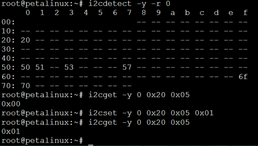
This subsystem provides 2 x 32-bit (8 x 8-bit) of general purpose parallel input and output (I/O) expansion for the I2C bus protocol.  Address of this module is 0x20. This module contains eight 8-bit registers for reading and writing (GPIO_register_1[7:0] to GPIO_register_1[31:24] and GPIO_register_2[7:0] to GPIO_register_2[31:24]) separately with address 0x00 to 0x07. These registers can be accessed with I2C commands in linux console or with i2c functions in FSBL code. To access these registers the following commands in linux console can be used:

  • To see the i2c bus addresses :                                     i2cdetect -y -r 0   
  • To read register of i2c to GPIO module:                            i2cget -y 0 0x20 <register address>     
  • To write data in a register of i2c to GPIO module:                 i2cset -y 0 0x20 <register address> <data>

Expand
titleexample, turn red LED D1 ON

Image Added

All eight registers can be read, but only two of them can be written from the linux console. 

I2C RegisterpermissionsaddressfunctionI2C command
GPIO_register_1(7 downto 0)readable0x00contains the CPLD Firmware Revision (not the PCB revision)read: i2cget -y 0 0x20 0x00
GPIO_register_1(15 downto 8) readable0x01contains the bootmode in bit 8 and bit 9. This register is read by the fsbl and printed
in the console as the bootmode during power up

GPIO_register_1(23 downto 16)readable0x02Bit 17 to 23 contain the DCDC power good signals and the DONE pin
GPIO_register_1(31 downto 24)readable/writeable0x03Bit 24 and 25 contain the bootmode, JTAG(b 00) or QSPI(b 10)write: i2cset -y 0 0x20 0x03 <0x02 or 0x00>
GPIO_register_2(7 downto 0)readable0x04Bit 0 to 3 show the state of the reset signals PS_POR, PS_SRST, ETH1_RESET, OTG_RST
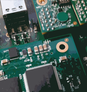
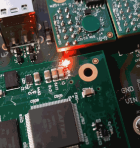
GPIO_register_2(15 downto 8)readable/writeable0x05Bit 8 can be controlled to change the state of the red LED D1 if no other red LED
condition is met
write: i2cset -y 0 0x20 0x05 <0x00 or 0x01>
GPIO_register_2(23 downto 16)readable0x06not used
GPIO_register_2(31 downto 24)readable0x07not used

...

Green LED D2

...


Appx. A: Change History and Legal Notices

Revision Changes

Document Change History

To get content of older revision  got to "Change History"  of this page and select older document revision number.

...

Page properties
hiddentrue
idComments
  • Note this list must be only updated, if the document is online on public doc!
  • It's semi automatically, so do following
    • Add new row below first

    • Copy "Page Information Macro(date)" Macro-Preview, Metadata Version number, Author Name and description to the empty row. Important Revision number must be the same as the Wiki document revision number Update Metadata = "Page Information Macro (current-version)" Preview+1 and add Author and change description. --> this point is will be deleted on newer pdf export template

    • Metadata is only used of compatibility of older exports

...


DateDocument RevisionCPLD Firmware RevisionSupported PCB RevisionAuthorsDescriptionFirmware release
Page info
modified-date
modified-date
dateFormatyyyy-MM-dd


Page info
current-version
current-version
prefixv.

...

REV02

...

REV02

Page info
modified-user
modified-user

  • CPLD Firmware Update
  • LED blinking


  • Power Sequencing 


  • I2C Interface to FPGA for status communication


Revision 02, 15.11.2023

2018-05-25


v.5

 REV01 RE02

John

Hartfiel


  • typo correction
  • add UART description

v.3REV01RE02John Hartfiel
  • REV01 , Firmware released  2016-06-27

2018-03-12

v.1


Page info
created-user
created-user

  • Initial release


All

Page info
modified-users
modified-users


Legal Notices

Include Page
IN:Legal Notices
IN:Legal Notices


Scroll Only


HTML
<style>
.wiki-content .columnLayout .cell.aside {
width: 0%;
}</style>


HTML
<style>
.wiki-content .columnLayout .cell.aside {
width: 20%;
}</style>


Scroll pdf ignore


Custom_fix_page_content

Table of contents

Table of Contents
outlinetrue