Page History
...
- _create_win_setup.cmd/_create_linux_setup.sh and follow instructions on shell:
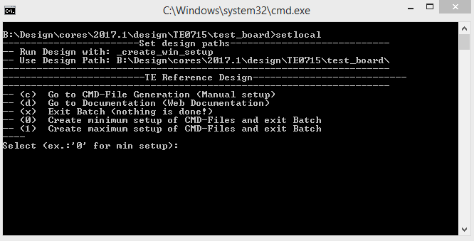
- Press 0 and enter for minimum setup
- (optional Win OS) Generate Virtual Drive or use short directory for the reference design (for example x:\<design name>)
- Create Project
- Select correct device and Xilinx install path on "design_basic_settings.cmd" and create Vivado project with "vivado_create_project_guimode.cmd"
Note: Select correct one, see TE Board Part Files
- Select correct device and Xilinx install path on "design_basic_settings.cmd" and create Vivado project with "vivado_create_project_guimode.cmd"
- Create HDF and export to prebuilt folder
- Run on Vivado TCL: TE::hw_build_design -export_prebuilt
Note: Script generate design and export files into \prebuilt\hardware\<short dir>. Use GUI is the same, except file export to prebuilt folder
- Run on Vivado TCL: TE::hw_build_design -export_prebuilt
- Create Linux (uboot.elf and image.ub) with exported HDF
- HDF is exported to "prebuilt\hardware\<short name>"
Note: HW Export from Vivado GUI create another path as default workspace. - Create Linux images on VM, see PetaLinux KICKstart
- Use TE Template from /os/petalinux
Note: run init_config.sh before you start petalinux config. This will set correct temporary path variable.
- Use TE Template from /os/petalinux
- HDF is exported to "prebuilt\hardware\<short name>"
- Add Linux files (uboot.elf and image.ub) to prebuilt folder
- "prebuilt\os\petalinux\default" or "prebuilt\os\petalinux\<short name>"
Notes: Scripts select "prebuilt\os\petalinux\<short name>", if exist, otherwise "prebuilt\os\petalinux\default"
- "prebuilt\os\petalinux\default" or "prebuilt\os\petalinux\<short name>"
- Gernerate Generate UBoot SREC:
- Create SDK Project with TE Scripts on Vivado TCL: TE::sw_run_sdk
- Create "uboot-dummy" application
Note: Use Hello World Example - Copy u.boot.elf into "\workspace\sdk\uboot-dummy\Debug"
- Open "uboot-dummy" properties → C/C++ Build → Settings and go into Build Steps Tap.
- Add to Post-build steps: mb-objcopy -O srec u-boot.elf u-boot.srec
- Press Apply or regenerate project
Note: srec is generated on "\workspace\sdk\uboot-dummy\Debug\u-boot.srec"
- Generate Programming Files with HSI/SDK
- Run on Vivado TCL: TE::sw_run_hsi
Note: Scripts generate applications and bootable files, which are defined in "sw_lib\apps_list.csv" - (alternative) Start SDK with Vivado GUI or start with TE Scripts on Vivado TCL: TE::sw_run_sdk
Note: See SDK Projects
- Run on Vivado TCL: TE::sw_run_hsi
- Copy "\prebuilt\software\<short name>\srec_spi_bootloader.elf" into "\firmware\microblaze_0\"
- Regernate Regenerate Vivado Project or Update Bitfile only with "srec_spi_bootloader.elf"
...
| Note |
|---|
Check Module and Carrier TRMs for proper HW configuration before you try any design. |
Programming
Xilinx documentation for programming and debugging: Vivado/SDK/SDSoC-Xilinx Software Programming and Debugging
...
- Connect JTAG and power on PCB
- (if not done) Select correct device and Xilinx install path on "design_basic_settings.cmd" and create Vivado project with "vivado_create_project_guimode.cmd" or open with "vivado_open_project_guimode.cmd", if generated.
- Type on Vivado Console: TE::pr_program_flash_mcsfile -swapp u-boot
Note: Alternative use SDK or setup Flash on Vivado manually - Reboot (if not done automatically)
...
- Prepare HW like described on section Programming
- Connect UART USB (most cases same as JTAG)
- Power on PCB
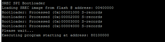
Note: 1. FPGA Loads Bitfile from Flash, SREC Bootloader from Bitfile Firmware loads U-Boot into DDR (This takes a while), U-boot loads LinuxU-boot load Linux from SD into DDRNote:
Boot process takes a while, please wait.
Linux
- Open Serial Console (e.g. putty)
- Speed: 9600
- COM Port: Win OS, see device manager, Linux OS see dmesg |grep tty (UART is *USB1)
- Linux Console:
Note: Wait until Linux boot finished For Linux Login use:- User Name: root
- Password: root
...
- Set kernel flash Address to 0x900000 and Kernel size to 0xA00000:
(--> Subsystem Auto Hardware Settings --> Flash Settings)- SUBSYSTEM_FLASH_AXI_QUAD_SPI_0_BANKLESS_PART0_SIZE = 0x400000
- SUBSYSTEM_FLASH_AXI_QUAD_SPI_0_BANKLESS_PART1_SIZE = 0x4E0000
- SUBSYSTEM_FLASH_AXI_QUAD_SPI_0_BANKLESS_PART2_SIZE = 0x20000
- SUBSYSTEM_FLASH_AXI_QUAD_SPI_0_BANKLESS_PART3_SIZE = 0xA00000
U-Boot
No changes.
Device Tree
...
Overview
Content Tools