Page History
| HTML |
|---|
<!-- Template Revision 1.0 Basic Notes - export PDF to download, if vivado revision is changed! - Template is for different design and SDSoC and examples, remove unused or wrong description! --> |
| Scroll Only (inline) |
|---|
Online version of this manual and other related documents can be found at https://wiki.trenz-electronic.de/display/PD/Trenz+Electronic+Documentation |
| Scroll pdf ignore | ||||
|---|---|---|---|---|
Table of contents
|
Overview
| HTML |
|---|
<!-- General Design description --> |
Key Features
| HTML |
|---|
<!-- Add Basic Key Features of the design (should be tested) --> |
- PetaLinux
- MicroBlaze
- SREC
- I2C
- Flash
- MIG
- FMeter
Revision History
| HTML |
|---|
<!-- - Add changes from design - Export PDF to download, if vivado revision is changed! --> |
| Date | Vivado | Project Built | Authors | Description |
|---|---|---|---|---|
| 2017-10-05 | 2017.2 | te0712-test_board-vivado_2017.2-build_03_20171005082148.zip te0712-test_board_noprebuilt-vivado_2017.2-build_03_20171005082225.zip | John Hartfiel | initial release |
Release Notes and Know Issues
| HTML |
|---|
<!-- - add known Design issues and general Notes for the current revision --> |
| Issues | Description | Workaround | To be fixed version |
|---|---|---|---|
| No known issues | --- | --- | --- |
Requirements
Software
| HTML |
|---|
<!-- Add needed external Software --> |
| Software | Version | Note |
|---|---|---|
| Vivado | 2017.2 | needed |
| SDK | 2017.2 | needed |
| PetaLinux | 2017.2 | needed |
Hardware
| HTML |
|---|
<!-- Hardware Support --> |
Basic description of TE Board Part Files is available on TE Board Part Files.
Complete List is available on <design name>/board_files/*_board_files.csv
Design supports following modules:
| Module Model | Board Part Short Name | PCB Revision Support | Notes |
|---|---|---|---|
| te0712-02-35-2i | 35_2i | 02 | |
| te0712-02-100-1i | 100_1i | 01,02 | |
| te0712-02-100-2c|3 | 100_2c | 01,02 | |
| te0712-02-200-1i|3 | 200_1i | 01,02 | |
| te0712-02-200-2i | 200_2i | 01,02 | |
| te0712-02-200-2c|3 | 200_2i | 01,02 |
Design supports following carriers:
| Carrier Model | Notes |
|---|---|
| TE0701 | |
| TE0703 | |
| TE0705 | |
| TE0706 | used as reference carrier |
| TEBA0841 |
Additional HW Requirements:
| Additional Hardware | Notes |
|---|---|
| USB Cable for JTAG/UART | Check Carrier Board and Programmer for correct typ |
| XMOD Programmer | Carrier Board dependent, only if carrier has no own FTDI |
Content
| HTML |
|---|
<!-- Remove unused content --> |
For general structure and of the reference design, see Project Delivery
Design Sources
| Type | Location | Notes |
|---|---|---|
| Vivado | <design name>/block_design <design name>/constraints <design name>/ip_lib <design name>/firmware | Vivado Project will be generated by TE Scripts |
| SDK/HSI | <design name>/sw_lib | Additional Software Template for SDK/HSI and apps_list.csv with settings for HSI |
| PetaLinux | <design name>/os/petalinux | PetaLinux template with current configuration |
Additional Sources
| Type | Location | Notes |
|---|---|---|
Prebuilt
| HTML |
|---|
<!-- <table width="100%"> <tr> <th>File </th> <th>File-Extension</th> <th>Description </th> </tr> <tr> <td>BIF-File </td> <td>*.bif </td> <td>File with description to generate Bin-File </td> </tr> <tr> <td>BIN-File </td> <td>*.bin </td> <td>Flash Configuration File with Boot-Image (Zynq-FPGAs) </td> </tr> <tr> <td>BIT-File </td> <td>*.bit </td> <td>FPGA Configuration File </td> </tr> <tr> <td>DebugProbes-File </td> <td>*.ltx </td> <td>Definition File for Vivado/Vivado Labtools Debugging Interface </td> </tr> <tr> <td>Debian SD-Image </td> <td>*.img </td> <td>Debian Image for SD-Card </td> </tr> <tr> <td>Diverse Reports </td> <td> --- </td> <td>Report files in different formats </td> </tr> <tr> <td>Hardware-Platform-Specification-Files</td> <td>*.hdf </td> <td>Exported Vivado Hardware Specification for SDK/HSI </td> </tr> <tr> <td>LabTools Project-File </td> <td>*.lpr </td> <td>Vivado Labtools Project File </td> </tr> <tr> <td>MCS-File </td> <td>*.mcs </td> <td>Flash Configuration File with Boot-Image (MicroBlaze or FPGA part only) </td> </tr> <tr> <td>MMI-File </td> <td>*.mmi </td> <td>File with BRAM-Location to generate MCS or BIT-File with *.elf content (MicroBlaze only) </td> </tr> <tr> <td>OS-Image </td> <td>*.ub </td> <td>Image with Linux Kernel (On Petalinux optional with Devicetree and RAM-Disk) </td> </tr> <tr> <td>Software-Application-File </td> <td>*.elf </td> <td>Software Application for Zynq or MicroBlaze Processor Systems </td> </tr> <tr> <td>SREC-File </td> <td>*.srec </td> <td>Converted Software Application for MicroBlaze Processor Systems </td> </tr> </table> --> |
File | File-Extension | Description |
|---|---|---|
| BIT-File | *.bit | FPGA (PL Part) Configuration File |
| DebugProbes-File | *.ltx | Definition File for Vivado/Vivado Labtools Debugging Interface |
| Diverse Reports | --- | Report files in different formats |
| Hardware-Platform-Specification-Files | *.hdf | Exported Vivado Hardware Specification for SDK/HSI and PetaLinux |
| LabTools Project-File | *.lpr | Vivado Labtools Project File |
MCS-File | *.mcs | Flash Configuration File with Boot-Image (MicroBlaze or FPGA part only) |
MMI-File | *.mmi | File with BRAM-Location to generate MCS or BIT-File with *.elf content (MicroBlaze only) |
| OS-Image | *.ub | Image with Linux Kernel (On Petalinux optional with Devicetree and RAM-Disk) |
| Software-Application-File | *.elf | Software Application for Zynq or MicroBlaze Processor Systems |
SREC-File | *.srec | Converted Software Application for MicroBlaze Processor Systems |
Download
Reference Design is only usable with the specified Vivado/SDK/PetaLinux/SDx version. Do never use different Versions of Xilinx Software for the same Project.
| HTML |
|---|
<!-- Add correct path:https://shop.trenz-electronic.de/en/Download/?path=Trenz_Electronic/TE0803/Reference_Design/2017.1/Starterkit --> |
Reference Design is available on:
Design Flow
| HTML |
|---|
<!-- Basic Design Steps Add/ Remove project specific --> |
| Note |
|---|
Reference Design is available with and without prebuilt files. It's recommended to use TE prebuilt files for first lunch. |
Trenz Electronic provides a tcl based built environment based on Xilinx Design Flow.
See also:Vivado/SDK/SDSoC
The Trenz Electronic FPGA Reference Designs are TCL-script based project. Command files for execution will be generated with "_create_win_setup.cmd" on Windows OS and "_create_linux_setup.sh" on Linux OS.
TE Scripts are only needed to generate the vivado project, all other additional steps are optional and can also executed by Xilinx Vivado/SDK GUI. For currently Scripts limitations on Win and Linux OS see: Project Delivery Currently limitations of functionality
- _create_win_setup.cmd/_create_linux_setup.sh and follow instructions on shell:
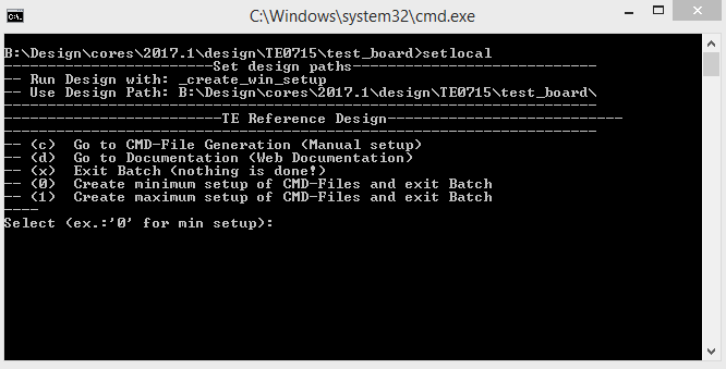
- Press 0 and enter for minimum setup
- (optional Win OS) Generate Virtual Drive or use short directory for the reference design (for example x:\<design name>)
- Create Project
- Select correct device and Xilinx install path on "design_basic_settings.cmd" and create Vivado project with "vivado_create_project_guimode.cmd"
Note: Select correct one, see TE Board Part Files
- Select correct device and Xilinx install path on "design_basic_settings.cmd" and create Vivado project with "vivado_create_project_guimode.cmd"
- Create HDF and export to prebuilt folder
- Run on Vivado TCL: TE::hw_build_design -export_prebuilt
Note: Script generate design and export files into \prebuilt\hardware\<short dir>. Use GUI is the same, except file export to prebuilt folder
- Run on Vivado TCL: TE::hw_build_design -export_prebuilt
- Create Linux (uboot.elf and image.ub) with exported HDF
- HDF is exported to "prebuilt\hardware\<short name>"
Note: HW Export from Vivado GUI create another path as default workspace. - Create Linux images on VM, see PetaLinux KICKstart
- Use TE Template from /os/petalinux
Note: run init_config.sh before you start petalinux config. This will set correct temporary path variable.
- Use TE Template from /os/petalinux
- HDF is exported to "prebuilt\hardware\<short name>"
- Add Linux files (uboot.elf and image.ub) to prebuilt folder
- "prebuilt\os\petalinux\default" or "prebuilt\os\petalinux\<short name>"
Notes: Scripts select "prebuilt\os\petalinux\<short name>", if exist, otherwise "prebuilt\os\petalinux\default"
- "prebuilt\os\petalinux\default" or "prebuilt\os\petalinux\<short name>"
- Generate UBoot SREC:
- Create SDK Project with TE Scripts on Vivado TCL: TE::sw_run_sdk
- Create "uboot-dummy" application
Note: Use Hello World Example - Copy u.boot.elf into "\workspace\sdk\uboot-dummy\Debug"
- Open "uboot-dummy" properties → C/C++ Build → Settings and go into Build Steps Tap.
- Add to Post-build steps: mb-objcopy -O srec u-boot.elf u-boot.srec
- Press Apply or regenerate project
Note: srec is generated on "\workspace\sdk\uboot-dummy\Debug\u-boot.srec"
- Generate Programming Files with HSI/SDK
- Run on Vivado TCL: TE::sw_run_hsi
Note: Scripts generate applications and bootable files, which are defined in "sw_lib\apps_list.csv" - (alternative) Start SDK with Vivado GUI or start with TE Scripts on Vivado TCL: TE::sw_run_sdk
Note: See SDK Projects
- Run on Vivado TCL: TE::sw_run_hsi
- Copy "\prebuilt\software\<short name>\srec_spi_bootloader.elf" into "\firmware\microblaze_0\"
- Regenerate Vivado Project or Update Bitfile only with "srec_spi_bootloader.elf"
Launch
Programming
| HTML |
|---|
<!-- Description of Block Design, Constrains... BD Pictures from Export... --> |
| Note |
|---|
Check Module and Carrier TRMs for proper HW configuration before you try any design. |
Xilinx documentation for programming and debugging: Vivado/SDK/SDSoC-Xilinx Software Programming and Debugging
QSPI
- Connect JTAG and power on PCB
- (if not done) Select correct device and Xilinx install path on "design_basic_settings.cmd" and create Vivado project with "vivado_create_project_guimode.cmd" or open with "vivado_open_project_guimode.cmd", if generated.
- Type on Vivado Console: TE::pr_program_flash_mcsfile -swapp u-boot
Note: Alternative use SDK or setup Flash on Vivado manually - Reboot (if not done automatically)
SD
Not used on this Example.
JTAG
Not used on this Example.
Usage
- Prepare HW like described on section Programming
- Connect UART USB (most cases same as JTAG)
- Power on PCB
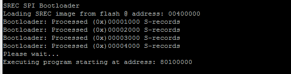
Note: FPGA Loads Bitfile from Flash, SREC Bootloader from Bitfile Firmware loads U-Boot into DDR (This takes a while), U-boot loads Linux from SD into DDR
Boot process takes a while, please wait.
Linux
- Open Serial Console (e.g. putty)
- Speed: 9600
- COM Port: Win OS, see device manager, Linux OS see dmesg |grep tty (UART is *USB1)
- Linux Console:
Note: Wait until Linux boot finished For Linux Login use:- User Name: root
- Password: root
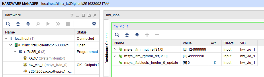
MGT Reference CLK Counter:
- Open Vivado HW-Manager and add VIO signal to dashboard (*.ltx located on prebuilt folder).
- Set radix from VIO signals to unsigned integer.
Note: Frequency Counter is inaccurate and displayed unit is Hz
- Set radix from VIO signals to unsigned integer.
MGT CLK is configured to 125MHz by default, second MIG output CLK is 50MHz.
System Design - Vivado
| HTML |
|---|
<!-- Description of Block Design, Constrains... BD Pictures from Export... --> |
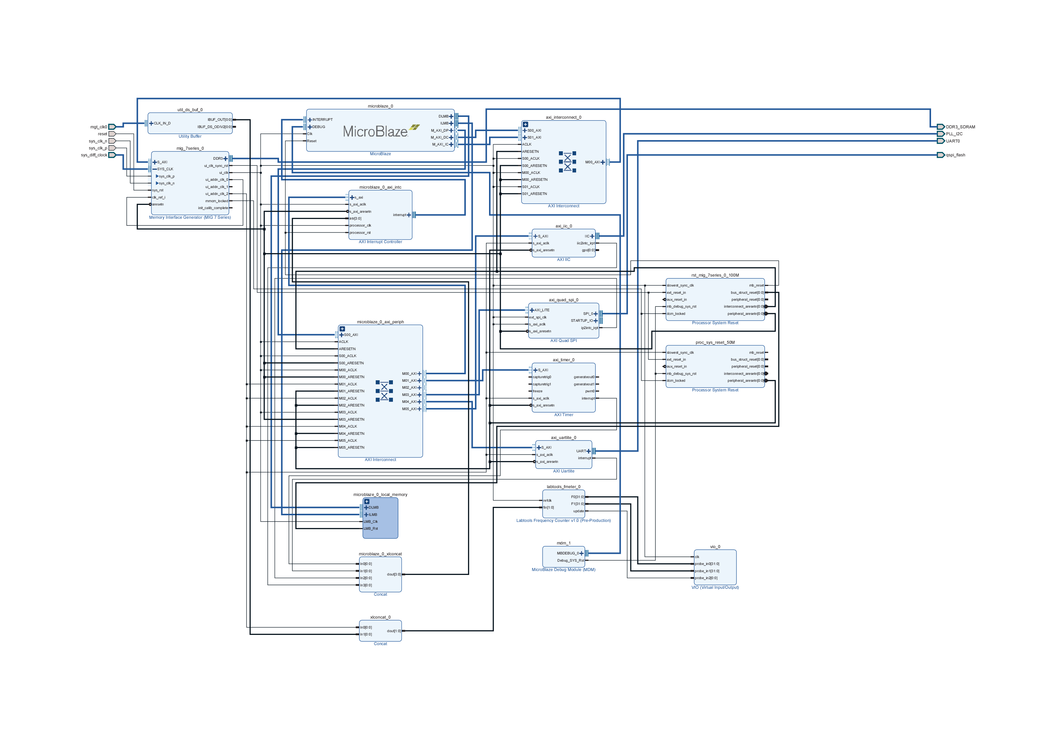
Block Design
Constrains
Basic module constrains
| Code Block | ||||
|---|---|---|---|---|
| ||||
set_property BITSTREAM.GENERAL.COMPRESS TRUE [current_design] set_property BITSTREAM.CONFIG.CONFIGRATE 66 [current_design] set_property CONFIG_VOLTAGE 3.3 [current_design] set_property CFGBVS VCCO [current_design] set_property CONFIG_MODE SPIx4 [current_design] set_property BITSTREAM.CONFIG.SPI_32BIT_ADDR YES [current_design] set_property BITSTREAM.CONFIG.SPI_BUSWIDTH 4 [current_design] set_property BITSTREAM.CONFIG.M1PIN PULLNONE [current_design] set_property BITSTREAM.CONFIG.M2PIN PULLNONE [current_design] set_property BITSTREAM.CONFIG.M0PIN PULLNONE [current_design] set_property BITSTREAM.CONFIG.USR_ACCESS TIMESTAMP [current_design] |
| Code Block | ||||
|---|---|---|---|---|
| ||||
set_property BITSTREAM.CONFIG.UNUSEDPIN PULLDOWN [current_design] |
Design specific constrain
| Code Block | ||||||||
|---|---|---|---|---|---|---|---|---|
| ||||||||
set_property PULLDOWN true [get_ports reset] |
Software Design - SDK/HSI
| HTML |
|---|
<!-- optional chapter separate sections for different apps --> |
For SDK project creation, follow instructions from:
Application
SREC SPI BootLoader
Add some Console outputs and changed Bootloader Read Address.
Template location: \sw_lib\sw_apps
xilisf_v5_8
Changed default Flash Typ to 5.
Template location: \sw_lib\sw_services
U-Boot
U-Boot.elf is generated with PetaLinux. SDK/HSI is used to generate u-boot.srec. Vivado to generate *.mcs
Software Design - PetaLinux
| HTML |
|---|
<!-- optional chapter --> |
Description currently not available.
Config
- Set kernel flash Address to 0x900000 and Kernel size to 0xA00000:
(--> Subsystem Auto Hardware Settings --> Flash Settings)- SUBSYSTEM_FLASH_AXI_QUAD_SPI_0_BANKLESS_PART0_SIZE = 0x400000
- SUBSYSTEM_FLASH_AXI_QUAD_SPI_0_BANKLESS_PART1_SIZE = 0x4E0000
- SUBSYSTEM_FLASH_AXI_QUAD_SPI_0_BANKLESS_PART2_SIZE = 0x20000
- SUBSYSTEM_FLASH_AXI_QUAD_SPI_0_BANKLESS_PART3_SIZE = 0xA00000
U-Boot
No changes.
Device Tree
No changes.
| Code Block | ||
|---|---|---|
| ||
/include/ "system-conf.dtsi"
/ {
};
|
Kernel
No changes.
Rootfs
No changes.
Applications
No changes.
Additional Software
| HTML |
|---|
<!-- Add Description for other Software, for example SI CLK Builder ... --> |
No additional software is needed.
Appx. A: Change History and Legal Notices
Document Change History
To get content of older revision got to "Change History" of this page and select older document revision number.
| HTML |
|---|
<!-- Generate new entry: 1:add new row below first 2:Copy Page Information Macro(date+user) Preview, Page Information Macro Preview 3.Update Metadate =Page Information Macro Preview+1 --> |
| Date | Document Revision | Authors | Description | ||||||||||||||||||||||
|---|---|---|---|---|---|---|---|---|---|---|---|---|---|---|---|---|---|---|---|---|---|---|---|---|---|
|
|
|
| ||||||||||||||||||||||
| 2017-10-05 | v.8 | John Hartfiel | Release 2017.2 | ||||||||||||||||||||||
| 2017-09-11 | v.1 |
| Initial release | ||||||||||||||||||||||
| All |
|
Legal Notices
| Include Page | ||||
|---|---|---|---|---|
|
Overview
Content Tools