Page History
...
Figure 1: TEI0005-01 Block Diagram.
Main Components
Figure 2: TEI0005-01 main components.
- FTDI FT2232H IC
- RED LED (Activity)
- Green LED (Power-on)
- Micro USB2 Connector
- 2x5-pin JTAG Connector (White dot marks Pin 1)
Signals, Interfaces and Pins
...
Following mechanical drawing shows the positions of the signal pins on the PCB of the module, which are numbered with the designators J1 ... J24.
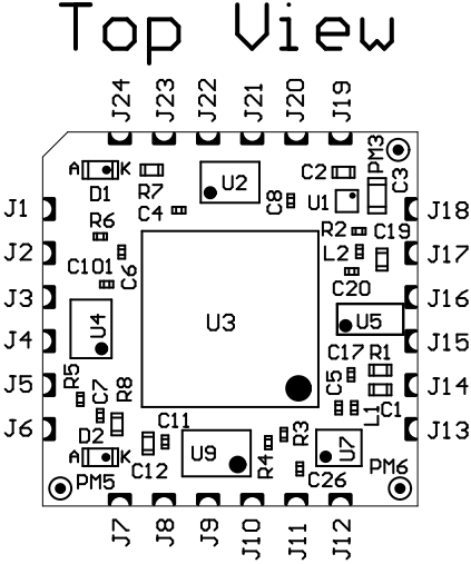
Figure 2: JTAG Module mechanical drawing.
...
| Pin Designator | Signal | Module Direction |
|---|---|---|
| J1 | reserved for future use | out |
| J2 | OEN (enable data transmitting data), low active | in |
| J3 | not connected | - |
| J4 | reserved for future use | out |
| J5 | UART RX | in |
| J6 | UART TX | out |
| J7 | not connected | - |
| J8 | not connected | - |
| J9 | not connected | - |
| J10 | not connected | - |
| J11 | not connected | - |
| J12 | not connected | - |
| J13 | not connected | - |
| J14 | USB-VBUS (USB Host supply voltage) | in |
| J15 | USB Data - | bidir |
| J16 | USB Data + | |
| J17 | GND | - |
| J18 | 3.3V output voltage from module | out |
| J19 | TCK | out |
| J20 | GND | - |
| J21 | TDI | out |
| 2J2 | TMS | out |
| 2J3 | VREF (Reference I/O-voltage from target board for JTAG and UART) | in |
| J24 | TDO | in |
...
Table 5: Hardware revision history.
Hardware revision number can be found on the PCB board together with the module model number separated by the dash.
Figure 4: Revision number.
Document Change History
| HTML |
|---|
<!-- Generate new entry: 1.add new row below first 2.Copy "Page Information Macro(date)" Macro-Preview, Metadata Version number, Author Name and description to the empty row. Important Revision number must be the same as the Wiki document revision number 3.Update Metadata = "Page Information Macro (current-version)" Preview+1 and add Author and change description. --> |
...
Overview
Content Tools