Page History
...
| HTML |
|---|
<!-- Add Basic Key Features of the design (should be tested) --> |
| Excerpt |
|---|
|
Revision History
| HTML |
|---|
<!-- - Add changes from design - Export PDF to download, if vivado revision is changed! --> |
| Date | Vivado | Project Built | Authors | Description |
|---|---|---|---|---|
| 2018-01-15 | 2017.4 | TE0808-StarterKit-vivado_2017.4-build_03_20180115092306.zip | John Hartfiel |
|
| 2017-12-18 | 2017.2 | TE0808-StarterKit_noprebuilt-vivado_2017.2-build_07_20171219151749.zip TE0808-StarterKit-vivado_2017.2-build_07_20171219151728.zip | John Hartfiel |
|
Release Notes and Know Issues
...
| Software | Version | Note |
|---|---|---|
| Vivado | 2017.24 | needed |
| SDK | 2017.24 | needed |
| PetaLinux | 2017.24 | needed |
Hardware
| HTML |
|---|
<!-- Hardware Support --> |
...
Reference Design is available on:
- TE0808 StartKit"StarterKit" Reference Design
Design Flow
| HTML |
|---|
<!-- Basic Design Steps Add/ Remove project specific --> |
...
- _create_win_setup.cmd/_create_linux_setup.sh and follow instructions on shell:
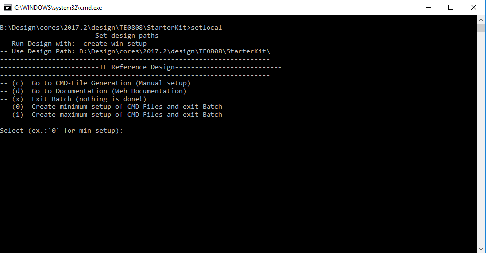
- Press 0 and enter for minimum setup
- (optional Win OS) Generate Virtual Drive or use short directory for the reference design (for example x:\<design name>)
- Create Project
- Select correct device and Xilinx install path on "design_basic_settings.cmd" and create Vivado project with "vivado_create_project_guimode.cmd"
Note: Select correct one, see TE Board Part Files
Important: Use Board Part Files, which ends with *_tebf0808
- Select correct device and Xilinx install path on "design_basic_settings.cmd" and create Vivado project with "vivado_create_project_guimode.cmd"
- Create HDF and export to prebuilt folder
- Run on Vivado TCL: TE::hw_build_design -export_prebuilt
Note: Script generate design and export files into \prebuilt\hardware\<short dir>. Use GUI is the same, except file export to prebuilt folder
- Run on Vivado TCL: TE::hw_build_design -export_prebuilt
- Create Linux (bl31.elf, uboot.elf and image.ub) with exported HDF
- HDF is exported to "prebuilt\hardware\<short name>"
Note: HW Export from Vivado GUI create another path as default workspace. - Create Linux images on VM, see PetaLinux KICKstart
- Use TE Template from /os/petalinux
Note: run init_config.sh before you start petalinux config. This will set correct temporary path variable.
- Use TE Template from /os/petalinux
- HDF is exported to "prebuilt\hardware\<short name>"
- Add Linux files (bl31.elf, uboot.elf and image.ub) to prebuilt folder
- "prebuilt\os\petalinux\default" or "prebuilt\os\petalinux\<short name>"
Notes: Scripts select "prebuilt\os\petalinux\<short name>", if exist, otherwise "prebuilt\os\petalinux\default"
- "prebuilt\os\petalinux\default" or "prebuilt\os\petalinux\<short name>"
- Generate Programming Files with HSI/SDK
- Run on Vivado TCL: TE::sw_run_hsi
Note: Scripts generate applications and bootable files, which are defined in "sw_lib\apps_list.csv" - (alternative) Start SDK with Vivado GUI or start with TE Scripts on Vivado TCL: TE::sw_run_sdk
Note: See SDK Projects
- Run on Vivado TCL: TE::sw_run_hsi
...
Xilinx documentation for programming and debugging: Vivado/SDK/SDSoC-Xilinx Software Programming and Debugging
QSPI
...
Optional for Boot.bin on QSPI Flash and image.ub on SD.
- Connect JTAG and power on carrier with module
- Open Vivado Project with "vivado_open_existing_project_guimode.cmd"
...
- or if not created, create with "vivado_
...
- create_project_guimode.cmd"
...
- Type on Vivado TCL Console:
...
- TE::pr_program_flash_
...
- binfile -swapp
...
- u-boot
...
Note:
...
- To program with SDK/Vivado GUI, use special FSBL (zynqmp_fsbl_flash) on setup
- Copy image.ub on SD-Card
- Insert SD-Card
SD
- Copy image.ub and Boot.bin on SD-Card.
- For correct prebuilt file location, see <design_name>/prebuilt/readme_file_location.txt
- Set Boot Mode to SD-Boot.
- Insert SD-Card in SD-Slot.
...
- Prepare HW like described on section Programming
- Connect UART USB (JTAG XMOD)
- Select SD Card as Boot Mode (or QSPI - depending on step 1)
Note: See TRM of the Carrier, which is used. - (Optional) Insert PCIe Card (detection depends on Linux driver. Only some basic drivers are installed)
- (Optional) Connect Sata Disc
- (Optional) Connect DisplayPort Monitor (List of usable Monitors: https://www.xilinx.com/support/answers/68671.html)
- (Optional) Connect Network Cable
- Power On PCB
Note: 1. ZynqMP Boot ROM loads PMU Firmware and FSBL from SD into OCM, 2. FSBL loads ATF(bl31.elf) and U-boot from SD/QSPI into DDR, 3. U-boot load Linux from SD into DDR.
...
Open Vivado HW-Manager and add VIO signal to dashboard (*.ltx located on prebuilt folder).
RGPIO Interface:
- Set Bit 31-28 to "1010" to activat RGPIO Interface of Master or Slave CPLD.
- Description: TEBF0808 Master CPLD#RGPIO, TEBF0808 Slave CPLD#RGPIO
- Set Bit 31-28 to "1010" to activat RGPIO Interface of Master or Slave CPLD.
- LED Control:
- XMOD 2(without green dot) and HD LED are accessible.
- XMOD 2(without green dot) and HD LED are accessible.
...
| HTML |
|---|
<!-- Description of Block Design, Constrains... BD Pictures from Export... --> |
Block Design
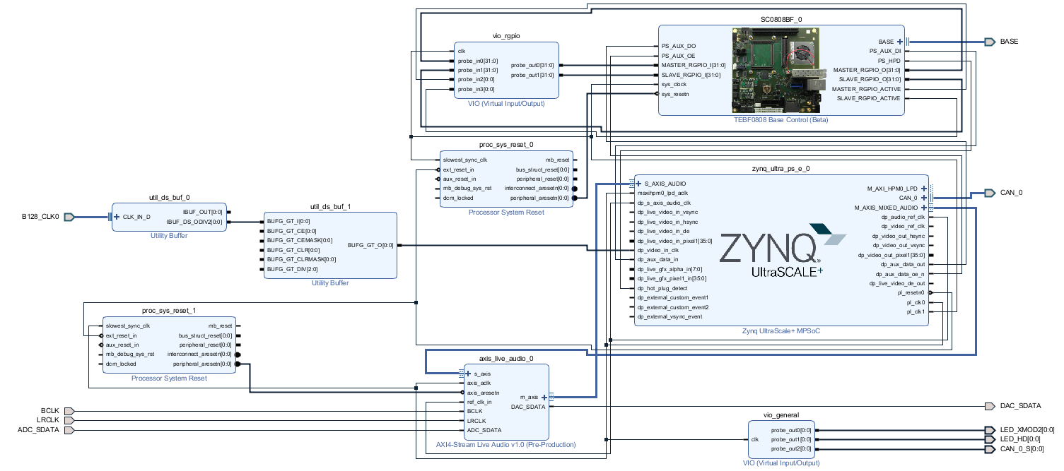
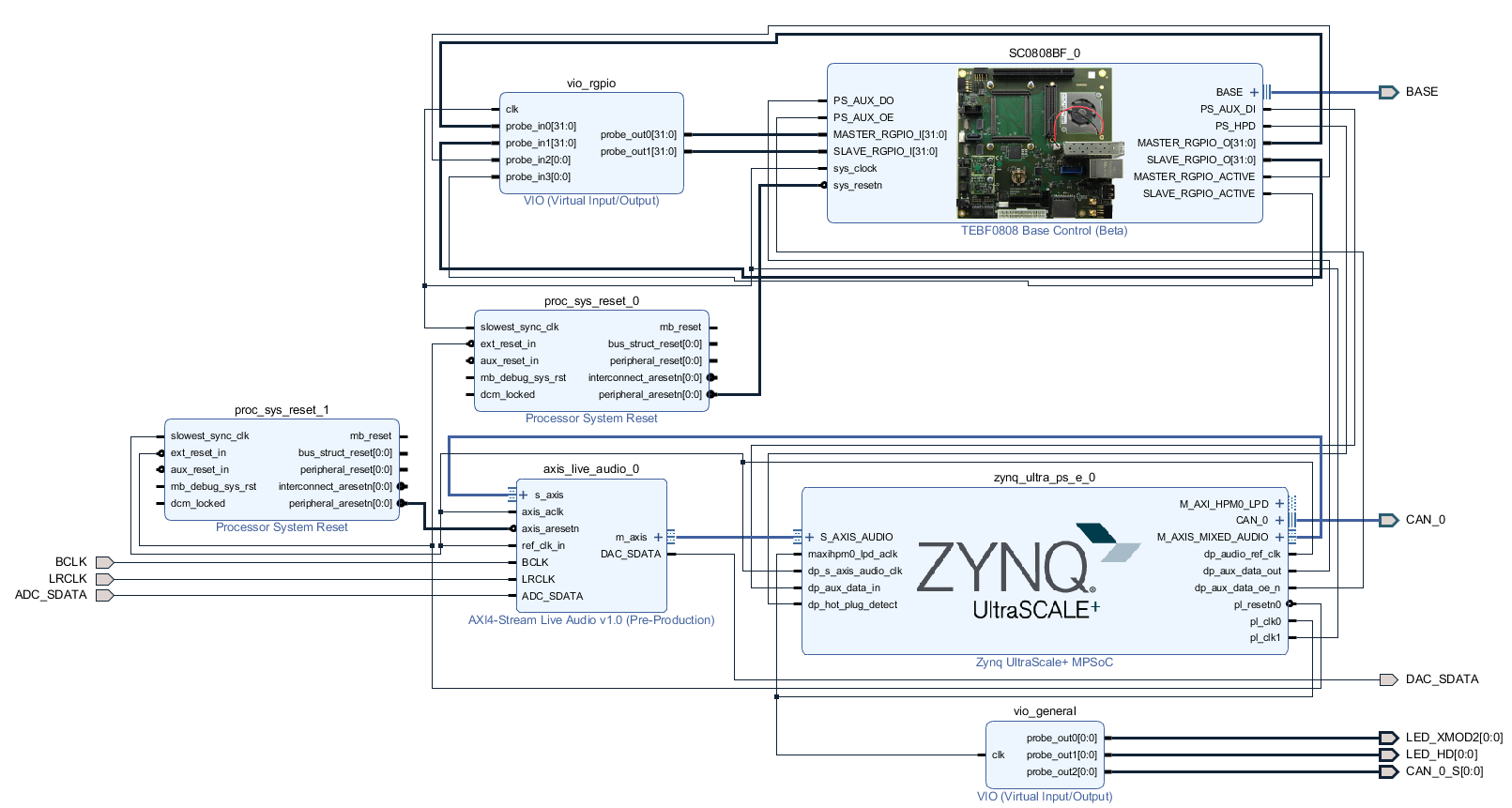
PS Interfaces
Activated interfaces:
| Type | Note |
|---|---|
| DDR | |
| QSPI | MIO |
| SD0 | MIO |
| SD1 | MIO |
| CAN0 | EMIO |
| I2C0 | MIO |
| PJTAG0 | MIO |
| UART0 | MIO |
| GPIO0 | MIO |
| SWDT0..1 | |
| TTC0..3 | |
| GEM3 | MIO |
| USB0 | MIO/GTP |
| PCIe | MIO/GTP |
| SATA | GTP |
...
| Code Block | ||||
|---|---|---|---|---|
| ||||
#set#LED_HD SC0 J3:31 set_property PACKAGE_PIN AH6J14 [get_ports {si570LED_clk_pHD[0]}] #setset_property IOSTANDARD LVDSLVCMOS18 [get_ports {si570LED_clk_pHD[0]}] #set #LED_XMOD SC17 J3:48 set_property IOSTANDARDPACKAGE_PIN LVDSB13 [get_ports {si570LED_clk_nXMOD2[0]}] # #setset_property PACKAGE_PINIOSTANDARD G8LVCMOS18 [get_ports {B230_CLK0_clk_pLED_XMOD2[0]}] #set #System Controller IP set_property PACKAGE_PIN J8A15 [get_ports {B229BASE_CLK1_clk_p[0]}] # #setsc10_io] set_property PACKAGE_PIN F25B15 [get_ports {B128_CLK0_clk_p[0]}] #LED_HD SC0 J3:31BASE_sc11] set_property PACKAGE_PIN J14C13 [get_ports {LED_HD[0]}]BASE_sc12] set_property IOSTANDARDPACKAGE_PIN LVCMOS18C14 [get_ports {LED_HD[0]}] #LED_XMOD SC17 J3:48 BASE_sc13] set_property PACKAGE_PIN B13E13 [get_ports {LED_XMOD2[0]}BASE_sc14] set_property IOSTANDARDPACKAGE_PIN LVCMOS18E14 [get_ports {LED_XMOD2[0]}] #System Controller IP BASE_sc15] set_property PACKAGE_PIN A15G13 [get_ports baseBASE_sc10_iosc5] set_property PACKAGE_PIN B15J15 [get_ports BASE_sc11sc6] set_property PACKAGE_PIN C13K15 [get_ports BASE_sc12sc7] set_property PACKAGE_PINIOSTANDARD C14LVCMOS18 [get_ports BASE_sc13sc5] set_property PACKAGE_PINIOSTANDARD E13LVCMOS18 [get_ports BASE_sc14sc6] set_property PACKAGE_PINIOSTANDARD E14LVCMOS18 [get_ports BASE_sc15sc7] set_property PACKAGE_PINIOSTANDARD G13LVCMOS18 [get_ports BASE_sc10_sc5io] set_property PACKAGE_PINIOSTANDARD J15LVCMOS18 [get_ports BASE_sc6sc11] set_property PACKAGE_PINIOSTANDARD K15LVCMOS18 [get_ports BASE_sc7sc12] set_property IOSTANDARD LVCMOS18 [get_ports BASE_sc5sc13] set_property IOSTANDARD LVCMOS18 [get_ports BASE_sc6sc14] set_property IOSTANDARD LVCMOS18 [get_ports BASE_sc7sc15] # PLL set#set_property IOSTANDARDPACKAGE_PIN LVCMOS18AH6 [get_ports base{si570_sc10_ioclk_p[0]}] set#set_property IOSTANDARD LVCMOS18LVDS [get_ports BASE_sc11] set_property IOSTANDARD LVCMOS18 [get_ports BASE_sc12] set{si570_clk_p[0]}] #set_property IOSTANDARD LVCMOS18LVDS [get_ports BASE_sc13] set_property IOSTANDARD LVCMOS18 [get_ports BASE_sc14] set_property IOSTANDARD LVCMOS18 [get_ports BASE_sc15] # PLL{si570_clk_n[0]}] # Clocks #set_property PACKAGE_PIN AH6J8 [get_ports {si570B229_CLK1_clk_p[0]}] #set_property IOSTANDARD LVDS [get_ports {si570_clk_p[0]}] #set_property IOSTANDARD LVDS [get_ports {si570_clk_n[0]}] # Clocks #set_property PACKAGE_PIN J8 [get_ports {B229_CLK1_clk_p[0]}] set_property PACKAGE_PACKAGE_PIN F25 [get_ports {B128_CLK0_clk_p[0]}] # SFP #set_property PACKAGE_PIN G8 [get_ports {B230_CLK0_clk_p}] # B230_RX3_P #set_property PACKAGE_PIN A4 [get_ports {SFP1_rxp}] # B230_TX3_P #set_property PACKAGE_PIN A8 [get_ports {SFP1_txp}] # B230_RX2_P #set_property PACKAGE_PIN B2 [get_ports {SFP2_rxp}] # B230_TX2_P #set_property PACKAGE_PIN B6 [get_ports {SFP2_txp}] # Audio Codec #LRCLK J3:49 B47_L9_N #BCLK J3:51 B47_L9_P #DAC_SDATA J3:53 B47_L7_N #ADC_SDATA J3:55 B47_L7_P set_property PACKAGE_PIN G14 [get_ports LRCLK ] set_property PACKAGE_PIN G15 [get_ports BCLK ] set_property PACKAGE_PIN E15 [get_ports DAC_SDATA ] set_property PACKAGE_PIN F15 [get_ports ADC_SDATA ] set_property IOSTANDARD LVCMOS18 [get_ports LRCLK ] set_property IOSTANDARD LVCMOS18 [get_ports BCLK ] set_property IOSTANDARD LVCMOS18 [get_ports DAC_SDATA ] set_property IOSTANDARD LVCMOS18 [get_ports ADC_SDATA ] # CAN #CAN RX SC19 J3:52 B47_L2_P #CAN TX SC18 J3:50 B47_L2_N #CAN S SC16 J3:46 B47_L3_N set_property PACKAGE_PIN A13 [get_ports CAN_0_S ] set_property IOSTANDARD LVCMOS18 [get_ports CAN_0_S ] set_property PACKAGE_PIN B14 [get_ports CAN_0_rx ] set_property IOSTANDARD LVCMOS18 [get_ports CAN_0_rx ] set_property PACKAGE_PIN A14 [get_ports CAN_0_tx ] set_property IOSTANDARD LVCMOS18 [get_ports CAN_0_tx ] |
Software Design - SDK/HSI
...
Application
FSBL
TE modified 2017.2 4 FSBL
Changes:
- Si5345Configuration, PCIe Reset over GPIO see xfsbl_board.c and xfsbl_board.h
- Add Si5345-Registers.h, si5345.c, si5345.h
PMU
zynqmp_fsbl_flash
TE modified 2017.4 FSBL
Changes:
- Set FSBL Boot Mode to JTAG
- Disable Memory initialisation
PMU
Xilinx Xilinx default PMU firmware.
Hello TE0808
...
| Code Block | ||
|---|---|---|
| ||
#include <configs/platform-auto.h> /* Extra U-Boot Env settings */#define CONFIG_SYS_BOOTM_LEN 0xF000000 #define CONFIGDFU_EXTRAALT_ENVINFO_SETTINGSRAM \ SERIAL_MULTI \ CONSOLE_ARG \ PSSERIAL0"dfu_ram_info=" \ "nc=setenv stdout nc;"setenv stdin nc;\0dfu_alt_info " \ "ethaddr=00:0a:35:00:22:01\0" \ "importbootenv=echo \"Importing environment from SD ...\"; image.ub ram $netstart 0x1e00000\0" \ "env import -t ${loadbootenv_addr} $filesizedfu_ram=run dfu_ram_info && dfu 0 ram 0\0" \ "loadbootenv=load mmc $sdbootdev:$partid ${loadbootenv_addr} ${bootenv}\0" \ "sd_uEnvtxt_existence_test=test -e mmc $sdbootdev:$partid /uEnv.txt\0" \ "uenvboot=" \ "if run sd_uEnvtxt_existence_test; then" \ "run loadbootenv" \ "echo Loaded environment from ${bootenv};" \ "run importbootenv; \0" \ "sdboot=echo boot Petalinux; run uenvboot ; mmcinfo && fatload mmc 1 ${netstart} ${kernel_img} && bootm \0" \ "autoload=no\0" \ "clobstart=0x10000000\0" \ "netstart=0x10000000\0" \ "dtbnetstart=0x11800000\0" \ "loadaddr=0x10000000\0" \ "boot_img=BOOT.BIN\0" \ "load_boot=tftpboot ${clobstart} ${boot_img}\0" \ "update_boot=setenv img boot; setenv psize ${bootsize}; setenv installcmd \"install_boot\"; run load_boot ${installcmd}; setenv img; setenv psize; setenv installcmd\0" \ "install_boot=mmcinfo && fatwrite mmc 1 ${clobstart} ${boot_img} ${filesize}\0" \ "bootenvsize=0x40000\0" \ "bootenvstart=0x100000\0" \ "eraseenv=sf probe 0 && sf erase ${bootenvstart} ${bootenvsize}\0" \ "jffs2_img=rootfs.jffs2\0" \ "load_jffs2=tftpboot ${clobstart} ${jffs2_img}\0" \ "update_jffs2=setenv img jffs2; setenv psize ${jffs2size}; setenv installcmd \"install_jffs2\"; run load_jffs2 test_img; setenv img; setenv psize; setenv installcmd\0" \ "sd_update_jffs2=echo Updating jffs2 from SD; mmcinfo && fatload mmc 1:1 ${clobstart} ${jffs2_img} && run install_jffs2\0" \ "install_jffs2=sf probe 0 && sf erase ${jffs2start} ${jffs2size} && " \ "sf write ${clobstart} ${jffs2start} ${filesize}\0" \ "kernel_img=image.ub\0" \ "load_kernel=tftpboot ${clobstart} ${kernel_img}\0" \ "update_kernel=setenv img kernel; setenv psize ${kernelsize}; setenv installcmd \"install_kernel\"; run load_kernel ${installcmd}; setenv img; setenv psize; setenv installcmd\0" \ "install_kernel=mmcinfo && fatwrite mmc 1 ${clobstart} ${kernel_img} ${filesize}\0" \ "cp_kernel2ram=mmcinfo && fatload mmc 1 ${netstart} ${kernel_img}\0" \ "dtb_img=system.dtb\0" \ "load_dtb=tftpboot ${clobstart} ${dtb_img}\0" \ "update_dtb=setenv img dtb; setenv psize ${dtbsize}; setenv installcmd \"install_dtb\"; run load_dtb test_img; setenv img; setenv psize; setenv installcmd\0" \ "sd_update_dtb=echo Updating dtb from SD; mmcinfo && fatload mmc 1:1 ${clobstart} ${dtb_img} && run install_dtb\0" \ "fault=echo ${img} image size is greater than allocated place - partition ${img} is NOT UPDATED\0" \ "test_crc=if imi ${clobstart}; then run test_img; else echo ${img} Bad CRC - ${img} is NOT UPDATED; fi\0" \ "test_img=setenv var \"if test ${filesize} -gt ${psize}\\; then run fault\\; else run ${installcmd}\\; fi\"; run var; setenv var\0" \ "netboot=tftpboot "thor_ram=run dfu_ram_info && thordown 0 ram 0\0" #define DFU_ALT_INFO \ DFU_ALT_INFO_RAM /*Required for uartless designs */ #ifndef CONFIG_BAUDRATE #define CONFIG_BAUDRATE 115200 #ifdef CONFIG_DEBUG_UART #undef CONFIG_DEBUG_UART #endif #endif /*select sd instead of mmc for autoboot */ #define CONFIG_BOOTCOMMAND "run uenvboot; mmcinfo && fatload mmc 1 ${netstart} ${kernel_img} && bootm\0" \ "default_bootcmd=run cp_kernel2ram && bootm ;bootm ${netstart}\0" \ """ |
Device Tree
| Code Block | ||
|---|---|---|
| ||
/include/ "system-conf.dtsi"
/ {
};

/* default */

/* SD */

&sdhci1 {
    // disable-wp;
    no-1-8-v;

};
/* ETH PHY */

&gem3 {
    phy-handle = <&phy0>;
    phy0: phy0@1 {
        device_type = "ethernet-phy";
        reg = <1>;
    };
};

/* QSPI */

&qspi {
    #address-cells = <1>;
    #size-cells = <0>;
    status = "okay";
    flash0: flash@0 {
        // compatible = "n25q256a";
        reg = <0x0>;
        #address-cells = <1>;
        #size-cells = <1>;
    };
};

/* I2C */

&i2c0 {
    i2cswitch@73 { // u
        compatible = "nxp,pca9548";
        #address-cells = <1>;
        #size-cells = <0>;
        reg = <0x73>;
        i2c-mux-idle-disconnect;

        i2c@2 { // PCIe
            #address-cells = <1>;
            #size-cells = <0>;
            reg = <2>;
        };
        i2c@3 { // i2c SFP
            #address-cells = <1>;
            #size-cells = <0>;
            reg = <3>;
        };
        i2c@4 { // i2c SFP
            #address-cells = <1>;
            #size-cells = <0>;
            reg = <4>;
        };
        i2c@5 { // i2c EEPROM
            #address-cells = <1>;
            #size-cells = <0>;
            reg = <5>;
        };
        i2c@6 { // i2c FMC
            #address-cells = <1>;
            #size-cells = <0>;
            reg = <6>;

            si570_2: clock-generator3@5d {
                #clock-cells = <0>;
                compatible = "silabs,si570";
                reg = <0x5d>;
                temperature-stability = <50>;
                factory-fout = <156250000>;
                clock-frequency = <78800000>;
            };
        };
        i2c@7 { // i2c USB HUB
            #address-cells = <1>;
            #size-cells = <0>;
            reg = <7>;
        };
    };
    i2cswitch@77 { // u
        compatible = "nxp,pca9548";
        #address-cells = <1>;
        #size-cells = <0>;
        reg = <0x77>;
        i2c-mux-idle-disconnect;
        i2c@0 { // i2c PMOD
            #address-cells = <1>;
            #size-cells = <0>;
            reg = <0>;
        };
        i2c@1 { // i2c Audio Codec
            #address-cells = <1>;
            #size-cells = <0>;
            reg = <1>;
            /*
            adau1761: adau1761@38 {
                compatible = "adi,adau1761";
                reg = <0x38>;
            };
            */
        };
        i2c@2 { // i2c FireFly A
            #address-cells = <1>;
            #size-cells = <0>;
            reg = <2>;
        };
        i2c@3 { // i2c FireFly B
            #address-cells = <1>;
            #size-cells = <0>;
            reg = <3>;
        };
        i2c@4 { // i2c PLL
            #address-cells = <1>;
            #size-cells = <0>;
            reg = <4>;
        };
        i2c@5 { // i2c SC
            #address-cells = <1>;
            #size-cells = <0>;
            reg = <5>;
        };
        i2c@6 { // i2c
            #address-cells = <1>;
            #size-cells = <0>;
            reg = <6>;
        };
        i2c@7 { // i2c
            #address-cells = <1>;
            #size-cells = <0>;
            reg = <7>;
        };
    };
};

/* UNUSED DMA disable */

&lpd_dma_chan1 {
    status = "disabled";
};
&lpd_dma_chan2 {
    status = "disabled";
};
&lpd_dma_chan3 {
    status = "disabled";
};
&lpd_dma_chan4 {
    status = "disabled";
};
&lpd_dma_chan5 {
    status = "disabled";
};
&lpd_dma_chan6 {
    status = "disabled";
};
&lpd_dma_chan7 {
    status = "disabled";
};
&lpd_dma_chan8 {
    status = "disabled";
};
|
...
| Date | Document Revision | Authors | Description | ||||||||||||||||||||||
|---|---|---|---|---|---|---|---|---|---|---|---|---|---|---|---|---|---|---|---|---|---|---|---|---|---|
|
|
|
| ||||||||||||||||||||||
| 2017-12-20 | v.2 | John Hartfiel | Release 2017.2 | ||||||||||||||||||||||
| All |
|
...
Overview
Content Tools