...
| Date | Vivado | Project Built | Authors | Description |
|---|
| 2018-05-25 | 2017.4 | te0712-test_board-vivado_2017.4-build_10_20180525155402.zip
te0712-test_board_noprebuilt-vivado_2017.4-build_10_20180525155555.zip | John Hartfiel | - solved eth issue for REV01
- changed design + second design for REV01
|
| 2018-04-12 | 2017.4 | te0712-test_board-vivado_2017.4-build_07_20180412081225.zip
te0712-test_board_noprebuilt-vivado_2017.4-build_07_20180412081253.zip | John Hartfiel | - Bugfix Constrain File - ETH REFCLK, Timing
|
| 2018-03-28 | 2017.4 | te0712-test_board-vivado_2017.4-build_07_20180328145151.zip
te0712-test_board_noprebuilt-vivado_2017.4-build_07_20180328145135.zip | John Hartfiel | |
| 2018-01-08 | 2017.4 | te0712-test_board-vivado_2017.4-build_02_20180108155712.zip
te0712-test_board_noprebuilt-vivado_2017.4-build_02_20180108155735.zip | John Hartfiel | - No Design changes
- small constrain changes
|
| 2017-12-15 | 2017.2 | te0712-test_board-vivado_2017.2-build_07_20171215172447.zip
te0712-test_board_noprebuilt-vivado_2017.2-build_07_20171215172514.zip | John Hartfiel | - Add SI5338 initialisation with MCS
- Add Ethernet IP
|
| 2017-11-07 | 2017.2 | te0712-test_board-vivado_2017.2-build_05_20171107172917.zip
te0712-test_board_noprebuilt-vivado_2017.2-build_05_20171107172939.zip | John Hartfiel | - Add Wiki Link in Boart Part Files
- Set Correct Short Link for te0712-02-200-2c
|
| 2017-10-05 | 2017.2 | te0712-test_board-vivado_2017.2-build_03_20171005082148.zip
te0712-test_board_noprebuilt-vivado_2017.2-build_03_20171005082225.zip | John Hartfiel | |
...
| Issues | Description | Workaround | To be fixed version |
|---|
| For PCB REV01 only: prebuilt does not boot | There is a Pullup missing on REV01 I2C SCL, so SI5338 configuration over MCS fails | Remove MCS | next solved with 20180528 update |
| For PCB REV01 only: CLK1B is not available on | additional clk is not connected on PCB | use other internal generated CLK, maybe mor more effort is needed to get ETH running | solved with 20180528 update |
SREC SPI BootLoader default Offset | Default load offset is set to 0x400000 | Change manually on SDK to 0x5E0000 | next solved with 20180412 update |
Requirements
Software
...
Design supports following modules:
| Module Model | Board Part Short Name | PCB Revision Support | DDR | QSPI Flash | Others | Notes |
|---|
| te0712- |
02352i 35_2i | REV02 | 1GB | 32MB | te0712-02-100-1i | 100, REV0202, REV0202, REV02 | 1GB | 32MB | 2,5 mm connector |
|
| te0712- |
021002ca1002caREV02Micron QSPI Flash | 021i1i , REV02021i31i, REV022,5 mm connector | 022i 2i | 2c | REV01 | 1GB | 32MB | 2,5 mm connector |
|
| te0712-02-35-2i | 35_2i | REV02 | 1GB | 32MB |
|
|
| te0712-02-100-1i | 100_1i | REV02 | 1GB | 32MB |
|
|
| te0712-02- |
2002002cREV01, 200200REV01, | REV02 | 1GB | 32MB | 2,5 mm connector |
Design supports following carriers:
...
Additional HW Requirements:
...
Content
| HTML |
|---|
<!--
Remove unused content
--> |
For general structure and of the reference design, see Project Delivery
Design Sources
...
|
| te0712-02-100-2ca | 100_2ca | REV02 | 1GB | 32MB |
| Micron QSPI Flash |
| te0712-02-200-1i | 200_1i | REV02 | 1GB | 32MB |
|
|
te0712-02-200-1i3 | 200_1i | REV02 | 1GB | 32MB | 2,5 mm connector |
|
| te0712-02-200-2i | 200_2i | REV02 | 1GB | 32MB |
|
|
| te0712-02-200-2c | 200_2c | REV02 | 1GB | 32MB |
|
|
| te0712-02-200-2c3 | 200_2c | REV02 | 1GB | 32MB | 2,5 mm connector |
|
Design supports following carriers:
| Carrier Model | Notes |
|---|
| TE0701 |
|
| TE0703 | used as reference carrier |
| TE0705 |
|
| TE0706 |
|
| TEBA0841 |
|
Additional HW Requirements:
| Additional Hardware | Notes |
|---|
| USB Cable for JTAG/UART | Check Carrier Board and Programmer for correct typ |
| XMOD Programmer | Carrier Board dependent, only if carrier has no own FTDI |
Content
| HTML |
|---|
<!--
Remove unused content
--> |
For general structure and of the reference design, see Project Delivery
Design Sources
| Type | Location | Notes |
|---|
| Vivado | <design name>/block_design
<design name>/constraints
<design name>/ip_lib
<design name>/firmware | Vivado Project will be generated by TE Scripts |
| SDK/HSI | <design name>/sw_lib | Additional Software Template for SDK/HSI and apps_list.csv with settings for HSI |
| PetaLinux | <design name>/os/petalinux | PetaLinux template with current configuration |
Additional Sources
| Type | Location | Notes |
|---|
| SI5338 Project | \misc\SI5338 |
|
Prebuilt
| HTML |
|---|
<!--

<table width="100%">
<tr> <th>File </th> <th>File-Extension</ |
Additional Sources
...
Prebuilt
| HTML |
|---|
<!--

<table width="100%">
<tr> <th>File                                 </th> <th>File-Extension</th>  <th>Description                                                                              </th> </tr>
<tr> <td>BIF-File                             </td> <td>*.bif         </td>  <td>File with description to generate Bin-File                                               </td> </tr>
<tr> <td>BIN-File                             </td> <td>*.bin         </td>  <td>Flash Configuration File with Boot-Image (Zynq-FPGAs)                                    </td> </tr>
<tr> <td>BIT-File                             </td> <td>*.bit         </td>  <td>FPGA Configuration File                                                                  </td> </tr>
<tr> <td>DebugProbes-File                     </td> <td>*.ltx         </td>  <td>Definition File for Vivado/Vivado Labtools Debugging Interface                           </td> </tr>
<tr> <td>Debian SD-Image                      </td> <td>*.img         </td>  <td>Debian Image for SD-Card                                                                </td> </tr>
<tr> <td>Diverse Reports                      </td> <td>  ---         </td>  <td>Report files in different formats                                                        </td> </tr>
<tr> <td>Hardware-Platform-Specification-Files</td> <td>*.hdf         </td>  <td>Exported Vivado Hardware Specification for SDK/HSI                                       </td> </tr>
<tr> <td>LabTools Project-File                </td> <td>*.lpr         </td>  <td>Vivado Labtools Project File                                                             </td> </tr>
<tr> <td>MCS-File                             </td> <td>*.mcs         </td>  <td>Flash Configuration File with Boot-Image (MicroBlaze or FPGA part only)                  </td> </tr>
<tr> <td>MMI-File                             </td> <td>*.mmi         </td>  <td>File with BRAM-Location to generate MCS or BIT-File with *.elf content (MicroBlaze only) </td> </tr>
<tr> <td>OS-Image                             </td> <td>*.ub          </td>  <td>Image with Linux Kernel (On Petalinux optional with Devicetree and RAM-Disk)             </td> </tr>
<tr> <td>Software-Application-File            </td> <td>*.elf         </td>  <td>Software Application for Zynq or MicroBlaze Processor Systems                            </td> </tr>
<tr> <td>SREC-File                            </td> <td>*.srec        </td>  <td>Converted Software Application for MicroBlaze Processor Systems                          </td> </tr>
</table>
-->
|
...
- _create_win_setup.cmd/_create_linux_setup.sh and follow instructions on shell:
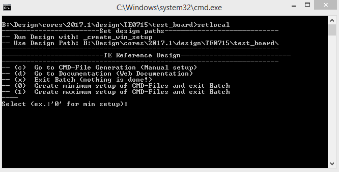
- Press 0 and enter for minimum setup
- (optional Win OS) Generate Virtual Drive or use short directory for the reference design (for example x:\<design name>)
- Create Project
- Select correct device and Xilinx install path on "design_basic_settings.cmd" and create Vivado project with "vivado_create_project_guimode.cmd"
Note: Select correct one, see TE Board Part Files
- Create HDF and export to prebuilt folder
- Run on Vivado TCL: TE::hw_build_design -export_prebuilt
Note: Script generate design and export files into \prebuilt\hardware\<short dir>. Use GUI is the same, except file export to prebuilt folder
- Create Linux (uboot.elf and image.ub) with exported HDF
- HDF is exported to "prebuilt\hardware\<short name>"
Note: HW Export from Vivado GUI create another path as default workspace. - Create Linux images on VM, see PetaLinux KICKstart
- Use TE Template from /os/petalinux
Note: run init_config.sh before you start petalinux config. This will set correct temporary path variable.
Important Note: Select correct Flash partition offset on petalinux-config: Subsystem Auto HW Settings → Flash Settings, FPGA+Boot+bootenv=0x900000 (increase automatically generate Boot partition), increas image size to A:, see Config
- Add Linux files (uboot.elf and image.ub) to prebuilt folder
- "prebuilt\os\petalinux\default" or "prebuilt\os\petalinux\<short name>"
Notes: Scripts select "prebuilt\os\petalinux\<short name>", if exist, otherwise "prebuilt\os\petalinux\default"
- (not longer needed manually: This will be done with Step 10.a automatically with newer scripts (2017.4.10) ) Generate UBoot SREC:
- Create SDK Project with TE Scripts on Vivado TCL: TE::sw_run_sdk
- Create "uboot-dummy" application
Note: Use Hello World Example - Copy u-boot.elf into "\workspace\sdk\uboot-dummy\Debug"
- Open "uboot-dummy" properties → C/C++ Build → Settings and go into Build Steps Tap.
- Add to Post-build steps: mb-objcopy -O srec u-boot.elf u-boot.srec
- Press Apply or regenerate project
Note: SREC is generated on "\workspace\sdk\uboot-dummy\Debug\u-boot.srec"
- Generate MCS Firmware (optional):
- Create SDK Project with TE Scripts on Vivado TCL: TE::sw_run_sdk
- Create "SCU" application
Note: Select MCS Microblaze and SCU Application - Select Release Built
- Regenerate App
- Generate Programming Files with HSI/SDK
- Run on Vivado TCL: TE::sw_run_hsi
Note: Scripts generate applications and bootable files, which are defined in "sw_lib\apps_list.csv" - (alternative) Start SDK with Vivado GUI or start with TE Scripts on Vivado TCL: TE::sw_run_sdk
Note: See SDK Projects
- Copy "\prebuilt\software\<short name>\srec_spi_bootloader.elf" into "\firmware\microblaze_0\"
- (optional) Copy "\\workspace\sdk\scu\Release\scu.elf" into "\firmware\microblaze_mcs_0\"
- Regenerate Vivado Project or Update Bitfile only with "srec_spi_bootloader.elf" and "scu.elf"
...
- Prepare HW like described on section 43679821 Programming
- Connect UART USB (most cases same as JTAG)
- Power on PCB
Note: FPGA Loads Bitfile from Flash,MCS Firmware configure SI5338 and starts Microblaze, SREC Bootloader from Bitfile Firmware loads U-Boot into DDR (This takes a while), U-boot loads Linux from QSPI Flash into DDR
...
- Open Serial Console (e.g. putty)
- Speed: 9600
- COM Port: Win OS, see device manager, Linux OS see dmesg |grep tty (UART is *USB1)
- Linux Console:
Note: Wait until Linux boot finished For Linux Login use:
- User Name: root
- Password: root
- You can use Linux shell now.
- ETH0 works with udhcpc
Vivado HW Manager:
- Open Vivado HW-Manager and add VIO signal to dashboard (*.ltx located on prebuilt folder).
- Set radix from VIO signals (MGT REF, MIG_OUT, CLK1B, CLK0) to unsigned integer.
Note: Frequency Counter is inaccurate and displayed unit is Hz - MGT REF~125MHz, MIG_50MHZ~50MHz., CLK1B ~50MHz, CLK0~100MHz
- Additional Infos: System reset from MCS and GIO outputs
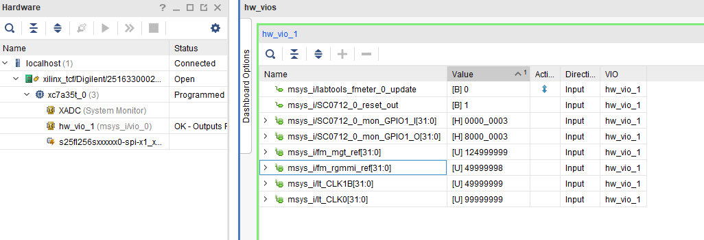 Image Removed
System Design - Vivado
| HTML |
|---|
<!--
Description of Block Design, Constrains...
BD Pictures from Export...
--> |
Block Design
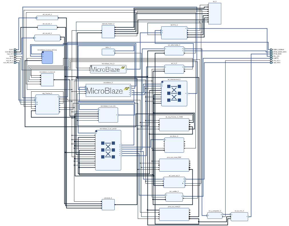 Image Removed
Constrains
Basic module constrains
- use:
- User Name: root
- Password: root
- You can use Linux shell now.
- ETH0 works with udhcpc
Vivado HW Manager:
- Open Vivado HW-Manager and add VIO signal to dashboard (*.ltx located on prebuilt folder).
- Set radix from VIO signals (MGT REF, MIG_OUT, CLK1B, CLK0) to unsigned integer.
Note: Frequency Counter is inaccurate and displayed unit is Hz - MGT REF~125MHz, MIG_50MHZ~50MHz., CLK1B ~50MHz, CLK0~100MHz
- Additional Infos: System reset from MCS and GIO outputs
Image Added
System Design - Vivado
| HTML |
|---|
<!--
Description of Block Design, Constrains...
BD Pictures from Export...
--> |
Block Design
REV02
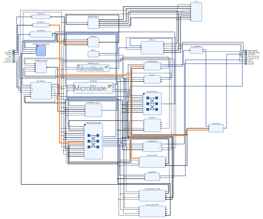 Image Added
REV01
Same as REV02 but 50 MHz ETH REV CLK is generated from MIG output with 180° Phase shift.
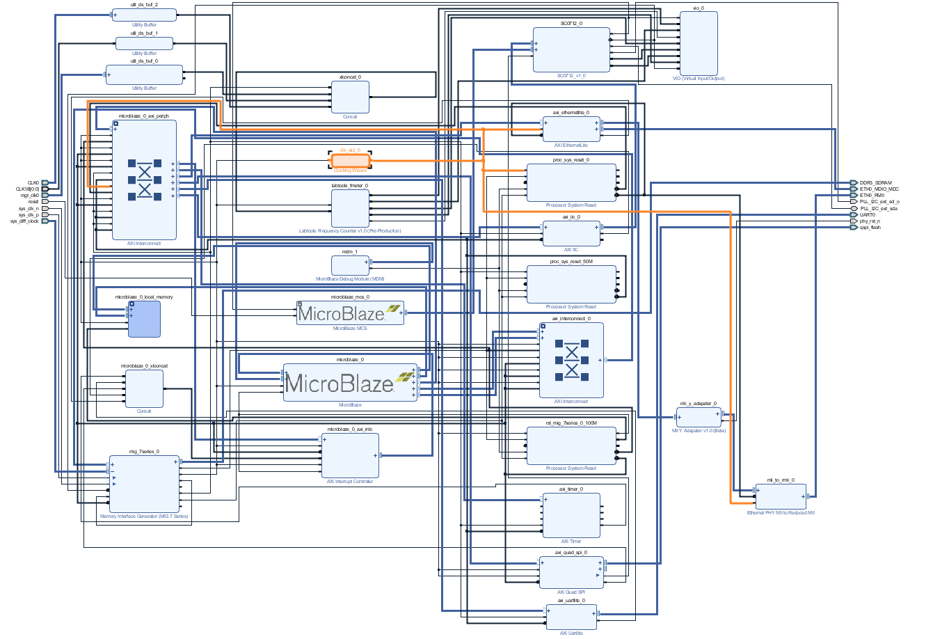 Image Added
Constrains
Basic module constrains
| Code Block |
|---|
| language | ruby |
|---|
| title | _i_bitgen_common.xdc |
|---|
|
set_property BITSTREAM.GENERAL.COMPRESS TRUE [current_design]
set_property BITSTREAM.CONFIG.CONFIGRATE 66 [current_design]
set_property CONFIG_VOLTAGE 3.3 [current_design]
set_property CFGBVS VCCO [current_design]
set_property CONFIG_MODE SPIx4 [current_design]
set_property BITSTREAM.CONFIG.SPI_32BIT_ADDR YES [current_design]
set_property BITSTREAM.CONFIG.SPI_BUSWIDTH 4 |
| Code Block |
|---|
| language | ruby |
|---|
| title | _i_bitgen_common.xdc |
|---|
|
set_property BITSTREAM.GENERAL.COMPRESS TRUE [current_design]
set_property BITSTREAM.CONFIG.CONFIGRATEM1PIN 66PULLNONE [current_design]
set_property BITSTREAM.CONFIG_VOLTAGE 3.3.M2PIN PULLNONE [current_design]
set_property CFGBVS VCCOBITSTREAM.CONFIG.M0PIN PULLNONE [current_design]

set_property BITSTREAM.CONFIG.USR_MODEACCESS SPIx4TIMESTAMP [current_design]
|
| Code Block |
|---|
| language | ruby |
|---|
| title | _i_bitgen.xdc |
|---|
|
set_property BITSTREAM.CONFIG.SPI_32BIT_ADDR YESUNUSEDPIN PULLDOWN [current_design]
design] |
Design specific constrain
| Code Block |
|---|
| language | ruby |
|---|
| title | _i_reset.xdc |
|---|
| linenumbers | true |
|---|
| collapse | true |
|---|
|
set_property BITSTREAM.CONFIG.SPI_BUSWIDTH 4PULLDOWN true [currentget_design]
set_property BITSTREAM.CONFIG.M1PIN PULLNONE [current_design]
set_property BITSTREAM.CONFIG.M2PIN PULLNONE [current_design]
set_property BITSTREAM.CONFIG.M0PIN PULLNONE [current_design]

set_property BITSTREAM.CONFIG.USR_ACCESS TIMESTAMP [current_design] |
| Code Block |
|---|
| language | ruby |
|---|
| title | _i_bitgen.xdc |
|---|
|
set_property BITSTREAM.CONFIG.UNUSEDPIN PULLDOWN [current_design] |
Design specific constrain
| Code Block |
|---|
| language | ruby |
|---|
| title | _i_reset.xdc |
|---|
| linenumbers | true |
|---|
| collapse | true |
|---|
|
set_property PULLDOWN true [get_ports reset] |
| Code Block |
|---|
| language | ruby |
|---|
| title | _i_io.xdc |
|---|
| linenumbers | true |
|---|
| collapse | true |
|---|
|
#I2C
#set_property PACKAGE_PIN W21 [get_ports PLL_I2C_scl_io]
#set_property IOSTANDARD LVCMOS33 [get_ports PLL_I2C_scl_io]
#set_property PACKAGE_PIN T20 [get_ports PLL_I2C_sda_io]
#set_property IOSTANDARD LVCMOS33 [get_ports PLL_I2C_sda_io] |
| Code Block |
|---|
| language | ruby |
|---|
| title | _i_io.xdc |
|---|
| linenumbers | true |
|---|
| collapse | true |
|---|
|
#I2C
set_property PACKAGE_PIN W21 [get_ports PLL_I2C_ext_scl_ioo]
set_property IOSTANDARD LVCMOS33 [get_ports PLL_I2C_ext_scl_ioo]
set_property PACKAGE_PIN T20 [get_ports PLL_I2C_ext_sda_io]
set_property IOSTANDARD LVCMOS33 [get_ports PLL_I2C_ext_sda_io]

#Reset
set_property PACKAGE_PIN T3 [get_ports reset]
set_property IOSTANDARD LVCMOS15 [get_ports reset]
#CLKS
set_property PACKAGE_PIN R4 [get_ports {CLK1B[0]}]
set_property IOSTANDARD LVCMOS15 [get_ports {CLK1B[0]}]
set_property PACKAGE_PIN K4 [get_ports {CLK0_clk_p[0]}]
set_property IOSTANDARD DIFF_SSTL15 [get_ports {CLK0_clk_p[0]}]

#ETH PHY
set_property PACKAGE_PIN N17 [get_ports phy_rst_n]
set_property IOSTANDARD LVCMOS33 [get_ports phy_rst_n |
...
...