Page History
...
| Excerpt |
|---|
|
Revision History
...
| Date | Vivado | Project Built | Authors | Description |
|---|---|---|---|---|
| 2018-07-1316 | 2018.2 | John Hartfiel | initial release |
...
- Open Serial Console (e.g. putty)
- Speed: 115200
- COM Port: Win OS, see device manager, Linux OS see dmesg |grep tty (UART is *USB1)
- Linux Console:
Note: Wait until Linux boot finished For Linux Login use:- User Name: root
- Password: root
- You can use Linux shell now.
- Todo
- Todo
Vivado HW Manager
Todo
System Design - Vivado
- I2C 0 Bus type: i2cdetect -y -r 0
- I2C 0 Bus type: i2cdetect -y -r 1
- ETH0 works with udhcpc
- ETH1 must be configured manually
- ifconfig eth1 up
- ifconfig eth1 <ip>
- ETH1 must be configured manually
- ifconfig eth1 up
- ifconfig eth1 <ip>
- RTC check: dmesg | grep rtc
- USB: insert USB Stick or lsusb
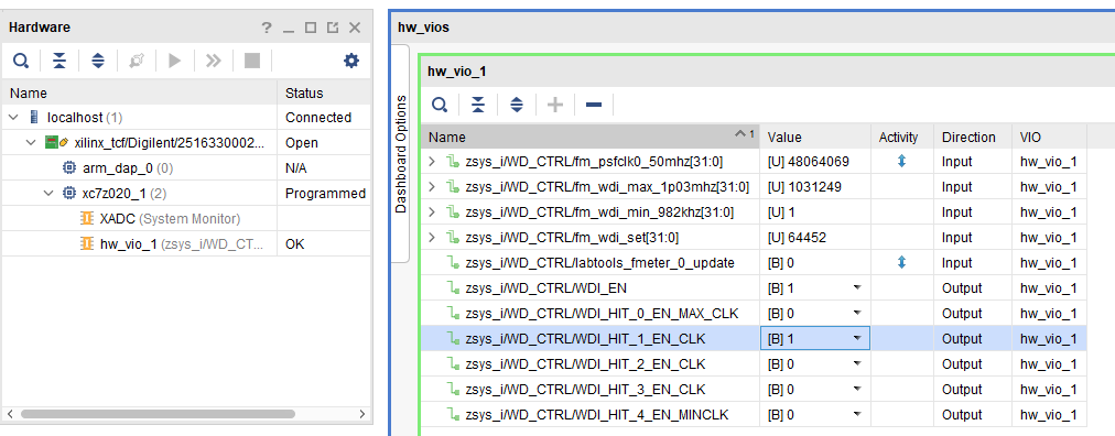
Vivado HW Manager
- Open Vivado Hardware Manager with auto connect.
- Use probe specification (*.ltx) from prebuilt folder.
- Add VIO signals to dashboard.
- Set radix for "fm_*" signals to unsigned integer.
- "fm_*" shows some clk frequencies (unit Hz). Note: inaccurate Reference CLK is used for frequency measurement.
- "WDI_EN" and "WDI_HIT_*_EN_CLK" enables FPGA watchdog control.
- Force WD to system reboot:
- Check on Hardware window VIO status is ok. (right click on vio symbol and click "commit output values to VIO core" for update).
- Enable one of the "WDI_HIT_*_EN_CLK" signals
- Enable "WDI_EN"
- To force system to reboot, disable WDI_HIT clocks.
System Design - Vivado
| HTML |
|---|
<!--
Description of |
| HTML |
<!--
Description of Block Design, Constrains...
BD Pictures from Export...
--> |
Block Design
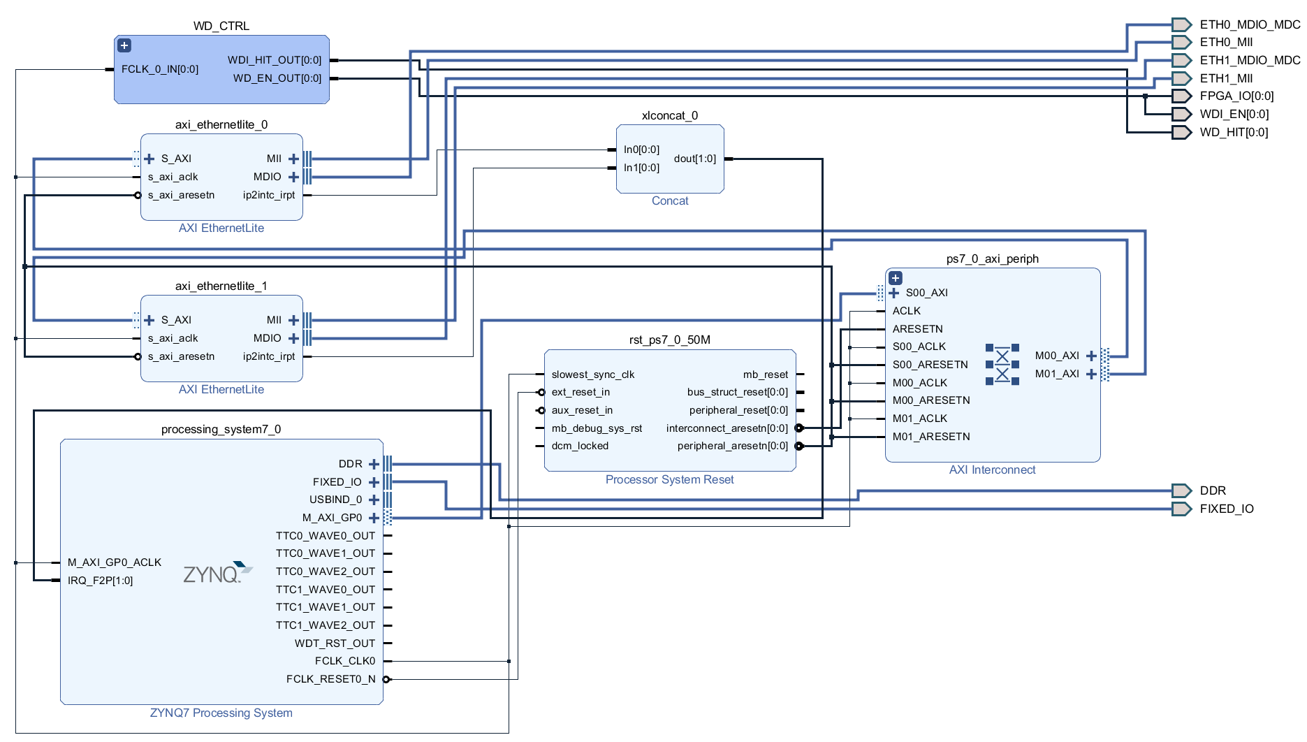
R Variant:
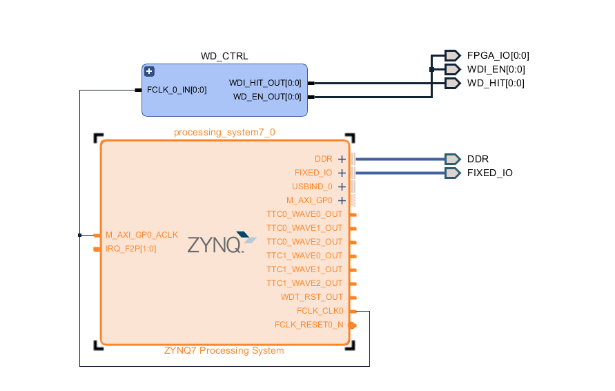
PS Interfaces
| Typ | Note |
|---|---|
| DDR | |
| QSPI | MIO |
| SD0 | MIO |
| I2C0 | MIO |
| I2C1 | MIO |
| UART0 | MIO |
| GPIO0 | MIO |
| SWDT0 | |
| TTC0..1 | |
| ETH00 | MIO |
| USB0 | MIO |
| PL-PS IRQ |
...
Source location: \sw_lib\sw_apps
zynqmp_fsbl
TE modified 2018.2 FSBL. Xilinx default FSBL on default setup. eMMC selection with FSBL possible.
Changes:
- Optional define for eMMC selection with FSBL (default SD selected)
- uncomment #define USE_EMMC on fsbl_hooks.c to select eMMC instead of SD
- See: fsbl_hooks.c, main.c
zynqmp_fsbl_flash
TE modified 2018.2 FSBL
...
| Code Block | ||
|---|---|---|
| ||
#include <configs/platform-auto.h>
#define CONFIG_SYS_BOOTM_LEN 0xF000000
#define DFU_ALT_INFO_RAM \
                "dfu_ram_info=" \
        "setenv dfu_alt_info " \
        "image.ub ram $netstart 0x1e00000\0" \
        "dfu_ram=run dfu_ram_info && dfu 0 ram 0\0" \
        "thor_ram=run dfu_ram_info && thordown 0 ram 0\0"

#define DFU_ALT_INFO_MMC \
        "dfu_mmc_info=" \
        "set dfu_alt_info " \
        "${kernel_image} fat 0 1\\\\;" \
        "dfu_mmc=run dfu_mmc_info && dfu 0 mmc 0\0" \
        "thor_mmc=run dfu_mmc_info && thordown 0 mmc 0\0"


/*Required for uartless designs */
#ifndef CONFIG_BAUDRATE
#define CONFIG_BAUDRATE 115200
#ifdef CONFIG_DEBUG_UART
#undef CONFIG_DEBUG_UART
#endif
#endif

/*Define CONFIG_ZYNQ_EEPROM here and its necessaries in u-boot menuconfig if you had EEPROM memory. */
#ifdef CONFIG_ZYNQ_EEPROM
#define CONFIG_SYS_I2C_EEPROM_ADDR_LEN         1
#define CONFIG_SYS_I2C_EEPROM_ADDR             0x54
#define CONFIG_SYS_EEPROM_PAGE_WRITE_BITS      4
#define CONFIG_SYS_EEPROM_PAGE_WRITE_DELAY_MS  5
#define CONFIG_SYS_EEPROM_SIZE                 1024 /* Bytes */
#define CONFIG_SYS_I2C_MUX_ADDR                0x74
#define CONFIG_SYS_I2C_MUX_EEPROM_SEL          0x4
#endif |
Device Tree
Note: for R assembly variant, remove ETH1, ETH2 and RTC
...
- RTC_DRV_ISL12022 (Not needed for R assembly variant, remove)
Rootfs
Activate:
- i2c-tools
...
Overview
Content Tools