Additional Software Template for SDK/HSI and apps_list.csv with settings for HSI
Additional Sources
...
anchor
Table_ADS
title
Additional design sources
...
Description
BIF-File
*.bif
File with description to generate Bin-File
BIN-File
*.bin
Flash Configuration File with Boot-Image (Zynq-FPGAs)
BIT-File
*.bit
FPGA (PL Part) Configuration File
DebugProbes-File
*.ltx
Definition File for Vivado/Vivado Labtools Debugging Interface
Debian SD-Image
*.img
Debian Image for SD-Card
Diverse Reports
---
Report files in different formats
Hardware-Platform-Specification-Files
*.hdf
Exported Vivado Hardware Specification for SDK/HSI and PetaLinux
LabTools Project-File
*.lpr
Vivado Labtools Project File
MCS-File
*.mcs
Flash Configuration File with Boot-Image (MicroBlaze or FPGA part only)
MMI-File
*.mmi
File with BRAM-Location to generate MCS or BIT-File with *.elf content (MicroBlaze only)
OS-Image
*.ub
Image with Linux Kernel (On Petalinux optional with Devicetree and RAM-Disk)
Software-Application-File
*.elf
Software Application for Zynq or MicroBlaze Processor Systems
SREC-File
*.srec
Converted Software Application for MicroBlaze Processor Systems
Prebuilt
Page properties
hidden
true
id
Comments
Notes :
prebuilt files
Template Table:
Scroll Title
anchor
Table_PF
title
Prebuilt files (only on ZIP with prebult content)
Scroll Table Layout
orientation
portrait
sortDirection
ASC
repeatTableHeaders
default
style
widths
sortByColumn
1
sortEnabled
false
cellHighlighting
true
File
File-Extension
Description
BIF-File
*.bif
File with description to generate Bin-File
BIN-File
*.bin
Flash Configuration File with Boot-Image (Zynq-FPGAs)
BIT-File
*.bit
FPGA (PL Part) Configuration File
DebugProbes-File
*.ltx
Definition File for Vivado/Vivado Labtools Debugging Interface
Debian SD-Image
*.img
Debian Image for SD-Card
Diverse Reports
---
Report files in different formats
Hardware-Platform-Specification-Files
*.hdf
Exported Vivado Hardware Specification for SDK/HSI and PetaLinux
LabTools Project-File
*.lpr
Vivado Labtools Project File
MCS-File
*.mcs
Flash Configuration File with Boot-Image (MicroBlaze or FPGA part only)
MMI-File
*.mmi
File with BRAM-Location to generate MCS or BIT-File with *.elf content (MicroBlaze only)
OS
Software-Application-
Image
File
*.
ub
Image with Linux Kernel (On Petalinux optional with Devicetree and RAM-Disk)
elf
Software Application
Software-Application-File
*.elf
Software Application
for Zynq or MicroBlaze Processor Systems
SREC-File
*.srec
Converted Software Application for MicroBlaze Processor Systems
Scroll Title
anchor
Table_PF
title
Prebuilt files (only on ZIP with prebult content)
Scroll Table Layout
orientation
portrait
sortDirection
ASC
repeatTableHeaders
default
style
widths
sortByColumn
1
sortEnabled
false
cellHighlighting
true
File
File-Extension
Description
BIT-File
*.bit
FPGA (PL Part) Configuration File
DebugProbes-File
*.ltx
Definition File for Vivado/Vivado Labtools Debugging Interface
Diverse Reports
---
Report files in different formats
Hardware-Platform-Specification-Files
*.hdf
Exported Vivado Hardware Specification for SDK/HSI and PetaLinux
LabTools Project-File
*.lpr
Vivado Labtools Project File
MCS-File
*.mcs
Flash Configuration File with Boot-Image (MicroBlaze or FPGA part only)
MMI-File
*.mmi
File with BRAM-Location to generate MCS or BIT-File with *.elf content (MicroBlaze only)
Software-Application-File
*.elf
Software Application for Zynq or MicroBlaze Processor Systems
SREC-File
*.srec
Converted Software Application for MicroBlaze Processor Systems
Download
Reference Design is only usable with the specified Vivado/SDK/PetaLinux/SDx version. Do never use different Versions of Xilinx Software for the same Project.
Page properties
hidden
true
id
Comments
Important set new Vivado version link on every Design update of new vivado version!
The Trenz Electronic FPGA Reference Designs are TCL-script based project. Command files for execution will be generated with "_create_win_setup.cmd" on Windows OS and "_create_linux_setup.sh" on Linux OS.
TE Scripts are only needed to generate the vivado project, all other additional steps are optional and can also executed by Xilinx Vivado/SDK GUI. For currently Scripts limitations on Win and Linux OS see: Project Delivery Currently limitations of functionality
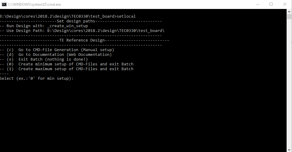
_create_win_setup.cmd/_create_linux_setup.sh and follow instructions on shell: Image Removed
Press 0 and enter for minimum setup
(optional Win OS) Generate Virtual Drive or use short directory for the reference design (for example x:\<design name>)
Create Project
Select correct device and Xilinx install path on "design_basic_settings.cmd" and create Vivado project with "vivado_create_project_guimode.cmd" Note: Select correct one, see TE Board Part Files
Create HDF and export to prebuilt folder
Run on Vivado TCL: TE::hw_build_design -export_prebuilt Note: Script generate design and export files into \prebuilt\hardware\<short dir>. Use GUI is the same, except file export to prebuilt folder
Generate Programming Files with HSI/SDK
Start with TE Scripts on Vivado TCL: TE::sw_run_hsi (optional) Start SDK with Vivado GUI or start with TE Scripts on Vivado TCL: TE::sw_run_sdk to generate files manually Note: See SDK Projects
(optional )Copy "prebuilt\software\<short dir>\srec_spi_bootloader.elf" into "\firmware\microblaze_0" (replace shipped one) and regenerate design again (HW (Step5)+SW(Step6 only a.))
Launch
Programming
Page properties
hidden
true
id
Comments
Note:
Programming and Startup procedure
Note
Check Module and Carrier TRMs for proper HW configuration before you try any design.
Open Vivado Project with "vivado_open_existing_project_guimode.cmd" or if not created, create with "vivado_create_project_guimode.cmd"
Type on Vivado TCL Console: TE::pr_program_flash_binfile -swapp hello_tef1001
Reboot PC
SD
Not supported.
JTAG
Connect Vivado HW Manager and program FPGA Note: PCIe enumeration will be not done in this case. SREC Bootloader need Hello TEF1001 application on QSPI Flash for output
Power On PCB Note: 1. FPGA Load Bitfile into FPGA, modified SREC Bootloader configure SI5338 and load application from QSPI into DDR (Depends on linker script)
JTAG/UART Console:
Launch the XSDB console on SDK (Xilinx → XSCT Console):
Reference Design is only usable with the specified Vivado/SDK/PetaLinux/SDx version. Do never use different Versions of Xilinx Software for the same Project.
Page properties
hidden
true
id
Comments
Important set new Vivado version link on every Design update of new vivado version!
The Trenz Electronic FPGA Reference Designs are TCL-script based project. Command files for execution will be generated with "_create_win_setup.cmd" on Windows OS and "_create_linux_setup.sh" on Linux OS.
TE Scripts are only needed to generate the vivado project, all other additional steps are optional and can also executed by Xilinx Vivado/SDK GUI. For currently Scripts limitations on Win and Linux OS see: Project Delivery Currently limitations of functionality
_create_win_setup.cmd/_create_linux_setup.sh and follow instructions on shell: Image Added
Press 0 and enter for minimum setup
(optional Win OS) Generate Virtual Drive or use short directory for the reference design (for example x:\<design name>)
Create Project
Select correct device and Xilinx install path on "design_basic_settings.cmd" and create Vivado project with "vivado_create_project_guimode.cmd" Note: Select correct one, see TE Board Part Files
Create HDF and export to prebuilt folder
Run on Vivado TCL: TE::hw_build_design -export_prebuilt Note: Script generate design and export files into \prebuilt\hardware\<short dir>. Use GUI is the same, except file export to prebuilt folder
Generate Programming Files with HSI/SDK
Start with TE Scripts on Vivado TCL: TE::sw_run_hsi (optional) Start SDK with Vivado GUI or start with TE Scripts on Vivado TCL: TE::sw_run_sdk to generate files manually Note: See SDK Projects
(optional ) Copy "prebuilt\software\<short dir>\srec_spi_bootloader.elf" into "\firmware\microblaze_0" (replace shipped one) and regenerate design again (HW (Step5)+SW(Step6 only a.))
(optional ) for SI5338 reprogramming with MCS:
Start SDK with Vivado GUI or start with TE Scripts on Vivado TCL: TE::sw_run_sdk to generate files manually
New Application with Project Name "SCU" and Processor "microblaze_mcs_0_microblaze_I", select TE Application "SCU-Firmware"
Create elf file
Copy "workspace\sdk\SCU\<release or debug>\SCU.elf" into "\firmware\microblaze_mcs_0" (replace shipped one) and regenerate design again (HW (Step5)+SW(Step6 only a.))
Launch
Programming
Page properties
hidden
true
id
Comments
Note:
Programming and Startup procedure
Note
Check Module and Carrier TRMs for proper HW configuration before you try any design.
Open Vivado Project with "vivado_open_existing_project_guimode.cmd" or if not created, create with "vivado_create_project_guimode.cmd"
Type on Vivado TCL Console: TE::pr_program_flash_mcsfile -swapp hello_tec0330
Reboot PC
SD
Not supported.
JTAG
Connect Vivado HW Manager and program FPGA Note: PCIe enumeration will be not done in this case. SREC Bootloader need Hello TEF1001 application on QSPI Flash for output
Power On PCB Note: 1. FPGA Load Bitfile into FPGA,MCS configure SI5338 and starts microblaze design, modified SREC Bootloader load application from QSPI into DDR (Depends on linker script)
JTAG/UART Console:
Launch the XSDB console on SDK (Xilinx → XSCT Console):
add notes for the signal either groups or topics, for example:
Control:
add controllable IOs with short notes..
Monitoring:
add short notes for signals which will be monitored only
SI5338_CLK0 Counter:
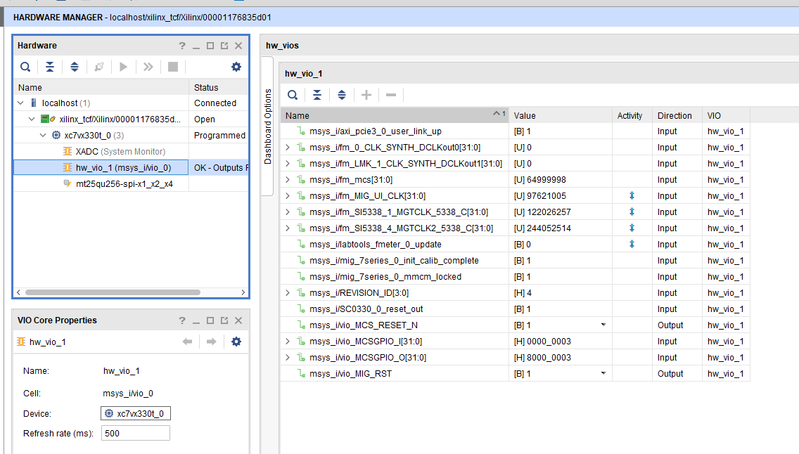
Open Vivado HW-Manager and add VIO signal to dashboard (*.ltx located on prebuilt folder).Set radix from VIO signals to unsigned integer.Note: Frequency Counter is inaccurate and displayed unit is Hz
Open Vivado HW Manager
Add VIO to Dashboard:
Set Radix to unsigned integer for FMeterCLKs (fm_*). Note measurement is not accurate
Control:
MCS Reset
MIG Reset
Read: All SI5338 CLKs (Unit Hz), PCIe Core User Link Up signal, MIG MMCM Lock signal, MIG Init Calibration Done signal Image Added
PC:
Use for example PCI-Z (Win) or KInfoCenter (Linux) to detect PCIe Card
Image Added
System Design - Vivado
Page properties
hidden
true
id
Comments
Note:
Add picture of HW Manager
add notes for the signal either groups or topics, for example:
Control:
add controllable IOs with short notes..
Monitoring:
add short notes for signals which will be monitored only
SI5338_CLK0 Counter:
Open Vivado HW-Manager and add VIO signal to dashboard (*.ltx located on prebuilt folder).Set radix from VIO signals to unsigned integer.Note: Frequency Counter is inaccurate and displayed unit is Hz
Open Vivado HW Manager
Add VIO to Dashboard:
Set Radix to unsigned integer for FMeterCLKs (labt_SI_*)
Control:
USER LEDs are selectable Note USR_CPLD_LED on PCB REV1 and REV02, USR_LED Matrix only on REV02