...
| Scroll Title |
|---|
| anchor | Figure_OV_BD |
|---|
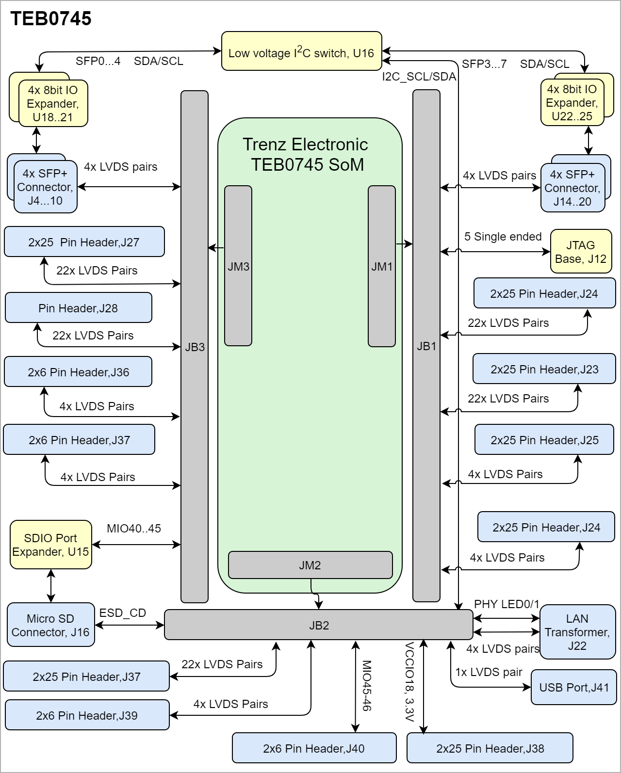
| title | TExxxx block diagram |
|---|
|
| Scroll Ignore |
|---|
| draw.io Diagram |
|---|
| border | false |
|---|
| viewerToolbar | true |
|---|
| |
|---|
| fitWindow | false |
|---|
| diagramDisplayName | |
|---|
| lbox | true |
|---|
| revision | 1112 |
|---|
| diagramName | TEB0745_OV_BD |
|---|
| simpleViewer | false |
|---|
| width | |
|---|
| links | auto |
|---|
| tbstyle | hidden |
|---|
| diagramWidth | 792640 |
|---|
|
|
| Scroll Only |
|---|
|
|
Main Components
...
| Scroll Title |
|---|
| anchor | Table_OV_IDS |
|---|
| title | Initial delivery state of programmable devices on the module |
|---|
|
| Scroll Table Layout |
|---|
| orientation | portrait |
|---|
| sortDirection | ASC |
|---|
| repeatTableHeaders | default |
|---|
| style | |
|---|
| widths | |
|---|
| sortByColumn | 1 |
|---|
| sortEnabled | false |
|---|
| cellHighlighting | true |
|---|
|
Storage device name | Content | Notes | Quad SPI Flash |
|---|
| EEPROM | DDR3 SDRAM | ... | Not Programmed |
|
|
Configuration Signals
| Page properties |
|---|
|
- Overview of Boot Mode, Reset, Enables.
|
...
| Scroll Title |
|---|
| anchor | Table_SIP_B2B |
|---|
| title | General PL I/O to B2B connectors information |
|---|
|
| Scroll Table Layout |
|---|
| orientation | portrait |
|---|
| sortDirection | ASC |
|---|
| repeatTableHeaders | default |
|---|
| style | |
|---|
| widths | |
|---|
| sortByColumn | 1 |
|---|
| sortEnabled | false |
|---|
| cellHighlighting | true |
|---|
|
| B2B Connector | Interfaces | Number of I/O | Notes |
|---|
J1
| User I/O | 48 singel ended, 24 Differential 2 singel ended | Connected to Bank 13 | 48 singel ended, 24 Differential 2 singel ended | Connected to Bank 12 | | JTAG Interface | 5 single ended | TCK, TDI, TMS, TDO, JTAG_EN | | SFP+ Connector | 8 Diff | SPF4....7_RX_N/P , SPF4....7_TX_N/P | J2
| Ethernet PHY | 4 Differential |
| | 2 single ended | PHY_LED0...1 | | USB | 1 Differential | OTG_N/P | | Control Signals | 3 single ended | PS_SRST, BOOTMODE, RST_IN_N | | Power Control Signal | 2 single ended | PWR_PS_OK, PWR_PL_OK | | I2C Bus | 2 single ended | I2C_SDA, I2C_SCL | | User I/O | 4 single ended | MIO12...15 | J3
| User I/O | 6 Single ended | MIO46...51 | | SD Card Connector | 6 Single ended | SD_CLK, SD_CMD, SD_DAT0...3 (MIO40...45) | | SFP+ Connector | 8 Differential | SPF0....3_RX_N/P , SPF0....3_TX_N/P |
|
JTAG Interface Base
JTAG access to the TExxxx TEB0745 SoM is available through B2B connector JMXJB1 and JB2. JTAG_EN is connected to J1-138, JTAG_EN can be activated through Switch SB1.
| Scroll Title |
|---|
| anchor | Table_SIP_JTG |
|---|
| title | JTAG pins connection |
|---|
|
| Scroll Table Layout |
|---|
| orientation | portrait |
|---|
| sortDirection | ASC |
|---|
| repeatTableHeaders | default |
|---|
| style | |
|---|
| widths | |
|---|
| sortByColumn | 1 |
|---|
| sortEnabled | false |
|---|
| cellHighlighting | true |
|---|
|
JTAG Signal Connector| TMS | J1-144 | | TDI | J1-142 | | TDO | J1-145 | | TCK | J1-143 | | JTAG_EN | J1-148 | |
MIO Pins
Pin | XMOD Header JB1 | Note |
|---|
| A | MIO15 | J2-129 | JB1-3 | UART Txd - input | | B | MIO14 | J2-127 | JB1-7 | UART Rxd - Output | | C | TCK | J1-143 | JB1-4 | JTAG interface signal | | D | TDO | J1-145 | JB1-8 | JTAG interface signal | | F | TDI | J1-142 | JB1-10 | JTAG interface signal | | H | TMS | J1-144 | JB1-12 | JTAG interface signal | | G | RST_IN_N | J2-131 | JB1-11 | RESET will be connected to Push Button on JTAG Programmer |
|
| Page properties |
|---|
|
you must fill the table below with group of MIOs which are connected to a specific components or peripherals, you do not have to specify pins in B2B, Just mention which B2B is connected to MIOs. The rest is clear in the Schematic.
Example:
| MIO Pin | Connected to | B2B | Notes |
|---|
| MIO12...14 | SPI_CS , SPI_DQ0... SPI_DQ3 SPI_SCK | J2 | QSPI |
| Scroll Title |
|---|
| anchor | Table_OBP_MIOs |
|---|
| title | MIOs pins |
|---|
|
| Scroll Table Layout |
|---|
|
| orientation | portrait |
|---|
| sortDirection | ASC |
|---|
| repeatTableHeaders | default |
|---|
style | widths | | sortByColumn | 1 |
|---|
| sortEnabled | false |
|---|
| cellHighlighting | true |
|---|
| MIO Pin | Connected to | B2B | Notes
On-board Peripherals
| Page properties |
|---|
|
Notes : - add subsection for every component which is important for design, for example:
- Two 100 Mbit Ethernet Transciever PHY
- USB PHY
- Programmable Clock Generator
- Oscillators
- eMMCs
- RTC
- FTDI
- ...
- DIP-Switches
- Buttons
- LEDs
|
...