Page History
...
- Connect your AnalogMAX DAQ1 via USB with your pc.
- Change FTDI FT2232H Port B to "OPTO Isolate" mode.
- Download FT_Prog 3.3.88.402 from "https://www.ftdichip.com/Support/Utilities.htm".
- Install FT_Prog.
- Start FT_Prog.
The window should look like Figure 1.
Scroll Title anchor Figure 1 title Figure 1: FT_Prog started Scroll Ignore draw.io Diagram border true viewerToolbar true fitWindow false diagramName FTDI_FT_Prog_1 simpleViewer false width diagramWidth 625 revision 1 Scroll Only 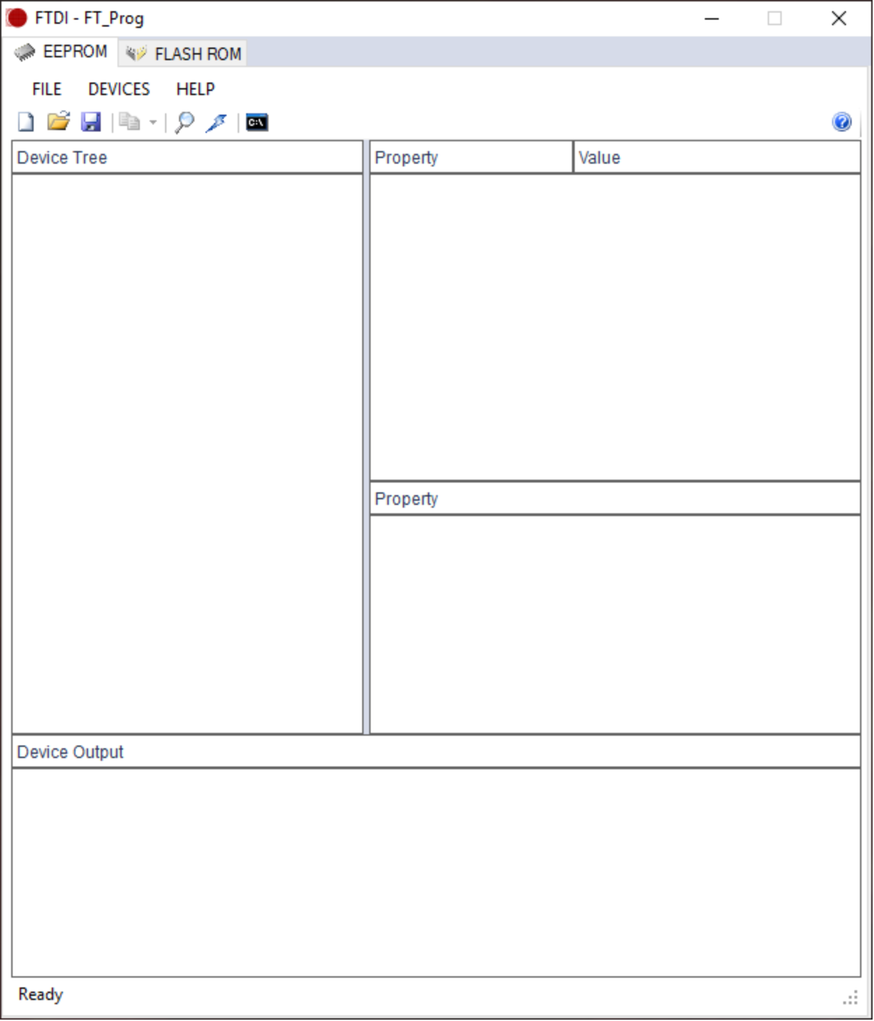
- Press "F5" or select "DEVICES → Scan and Parse" to find the FTDI chip.
The window should look like Figure 2.
Scroll Title anchor Figure 2 title Figure 2: FT_Prog port scanned Scroll Ignore draw.io Diagram border true viewerToolbar true fitWindow false diagramName FTDI_FT_Prog_2 simpleViewer false width diagramWidth 625 revision 1 Scroll Only 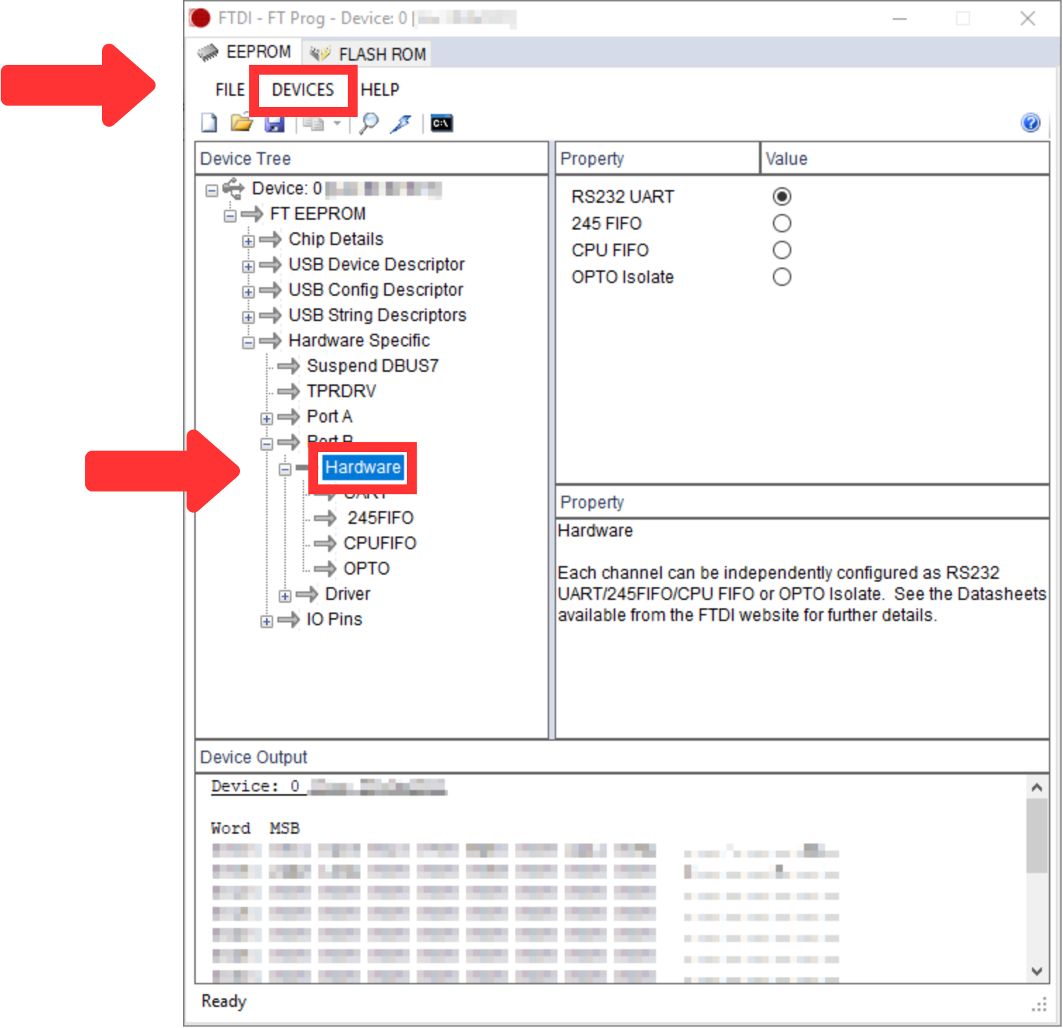
- Open the "Hardware Specific → Port B → Hardware" as visible in Figure 2.
- Select "OPTO Isolate" on the right side, as visible in Figure 3.
Scroll Title anchor Figure3 title Figure 3: FT_Prog "OPTP Isolate" selected Scroll Ignore draw.io Diagram border true viewerToolbar true fitWindow false diagramName FTDI_FT_Prog_3 simpleViewer false width diagramWidth 625 revision 1 Scroll Only 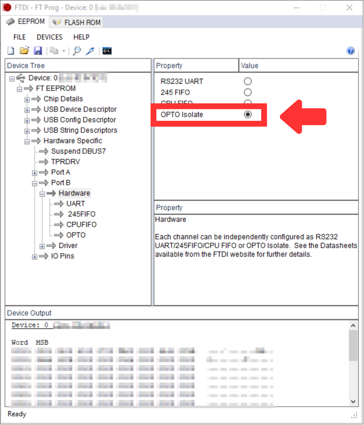
- Then, press "Ctrl+P" or select "DEVICES → PROGRAM" to change your FTDI FT2232H Port B to "OPTO Isolate" mode.
- Press "Program" in the new window, as visible in Figure 4.
Scroll Title anchor Figure4Figure 4 title Figure 4: FT_Prog "Program Devices" Scroll Ignore draw.io Diagram border true viewerToolbar true fitWindow false diagramName FTDI_FT_Program_Devices simpleViewer false width diagramWidth 563 revision 1 Scroll Only 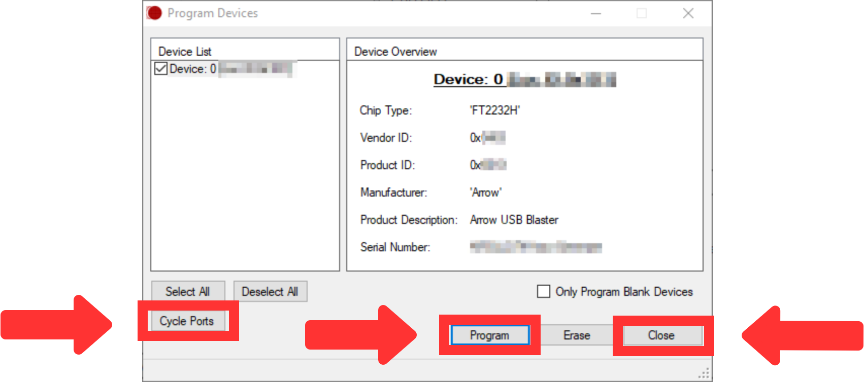
- After that, press "Cycle Ports" in the window shown in Figure 4 and then press "Close".
- After pressing "F5" and opening the path "Hardware Specific → Port B → Hardware", as visible in Figure 2, the value "OPTO Isolate" should be selected.
- Program the FPGA with new POF file.
- Download Quartus Prime Software from "https://www.intel.de/content/www/de/de/software/programmable/quartus-prime/download.html". The Lite Edition is sufficient.
- Install Quartus Prime.
- Install Arrow-USB-Blaster-Setup-2.2.exe from "https://shop.trenz-electronic.de/de/Download/?path=Trenz_Electronic/Software/Drivers/Arrow_USB_Programmer/Arrow_USB_Programmer_2.2".
- Start the Quartus Prime Programmer. The window should look like Figure 5.
Scroll Title anchor Figure5Figure 5 title Figure 5: Quartus Prime Programmer started Scroll Ignore draw.io Diagram border true viewerToolbar true fitWindow false diagramName Quartus_Prime_Programmer simpleViewer false width diagramWidth 882 revision 1 Scroll Only 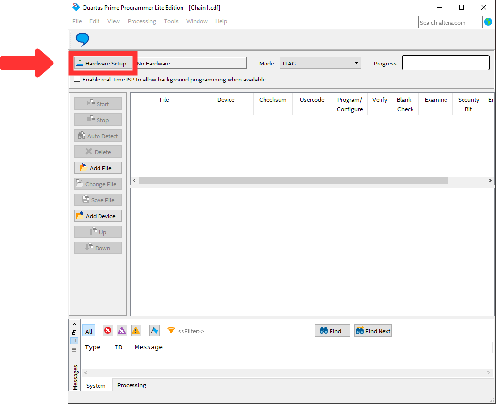
- The window should look like Figure 5.
- Press "Hardware Setup..." and select "Arrow-USB-Blaster [USBX]" in "Currently selected hardware" as visible in Figure 6, whereby the "X" in [USBX] is a placeholder.
Scroll Title anchor Figure6Figure 6 title Figure 6: Quartus Prime Programmer Hardware Setup Scroll Ignore draw.io Diagram border true viewerToolbar true fitWindow false diagramName Quartus_Prime_Programmer_Hardware_Setup simpleViewer false width diagramWidth 571 revision 1 Scroll Only 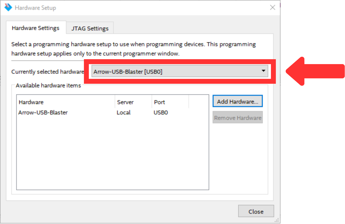
Then, press "Close" and return to the previous window. The window should look like Figure 7.
Scroll Title anchor Figure7Figure 7 title Figure 7: Quartus Prime Programmer Hardware Devices Setup Scroll Ignore draw.io Diagram border true viewerToolbar true fitWindow false diagramName Quartus_Prime_Programmer_2 simpleViewer false width diagramWidth 882 revision 1 Scroll Only 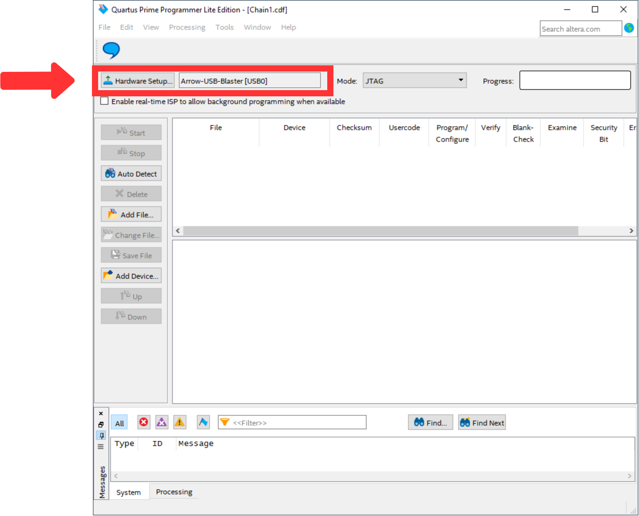
After that, use "Add File..." to select the file to program the FPGA. The window should look like Figure 8.
Scroll Title anchor Figure8Figure 8 title Figure 8: Quartus Prime Programmer POF selected Scroll Ignore draw.io Diagram border true viewerToolbar true fitWindow false diagramName Quartus_Prime_Programmer_POF_Selected simpleViewer false width diagramWidth 882 revision 1 Scroll Only 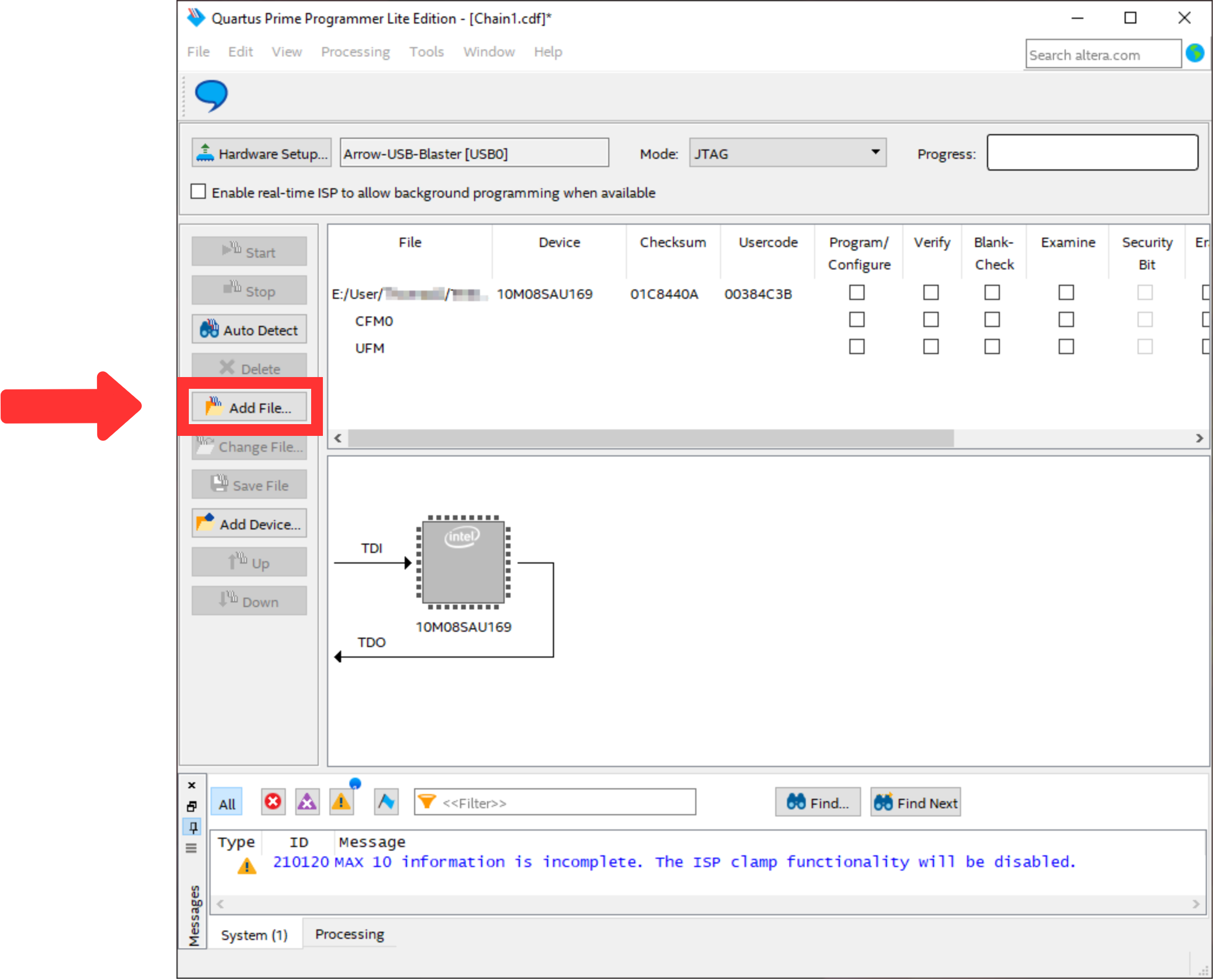
Mark the "Program/Configure" box for the selected file. Then, the window should look like Figure 109.
Scroll Title anchor Figure9Figure 9 title Figure 9: Quartus Prime Programmer POF selected Scroll Ignore draw.io Diagram border true viewerToolbar true fitWindow false diagramName Quartus_Prime_Programmer_Box_Checked simpleViewer false width diagramWidth 882 revision 1 Scroll Only 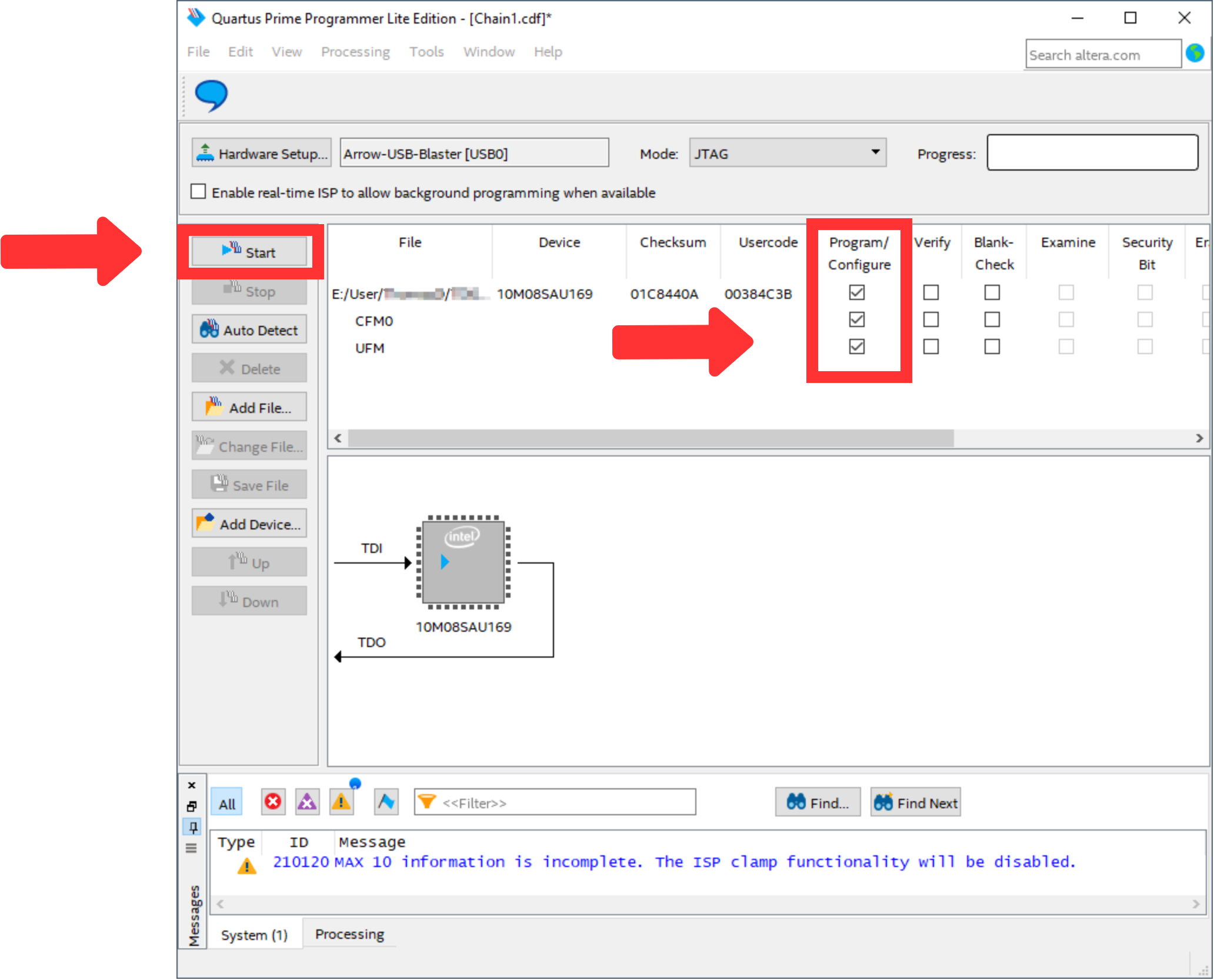
- To program the FPGA use the button "Start".
- The Quartus Prime Programmer can be closed.
- Figure out the correct COM port number for the AnalogMAX DAQ1 board.
- Open the device manager.
Open ports and identify the port used by the AnalogMAX DAQ1 as visible in Figure
1110.
Scroll Title anchor Figure10Figure 10 title Figure 10: Device Manager for COM port identification Scroll Ignore draw.io Diagram border true viewerToolbar true fitWindow false diagramName Device_Manager simpleViewer false width diagramWidth 782 revision 1 Scroll Only 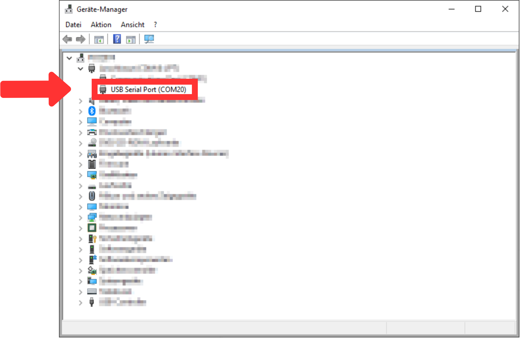
- Download adcapture.exe to local drive from "????????"
- Setup Visual Analog "External Tools..." custom menu item to launch adcapture.exe with commandline parameters.
- Download "Visual Analog" from "https://www.analog.com/en/design-center/interactive-design-tools/visualanalog.html".
- Install "Visual Analog"
Start "Visual Analog" and open an "Blank canvas". After that, the window should look like Figure 1211.
Scroll Title anchor Figure11Figure 11 title Figure 11: VisualAnalog started Scroll Ignore draw.io Diagram border true viewerToolbar true fitWindow false diagramName VisualAnalog_Started simpleViewer false width 600 diagramWidth 1921 revision 1 Scroll Only 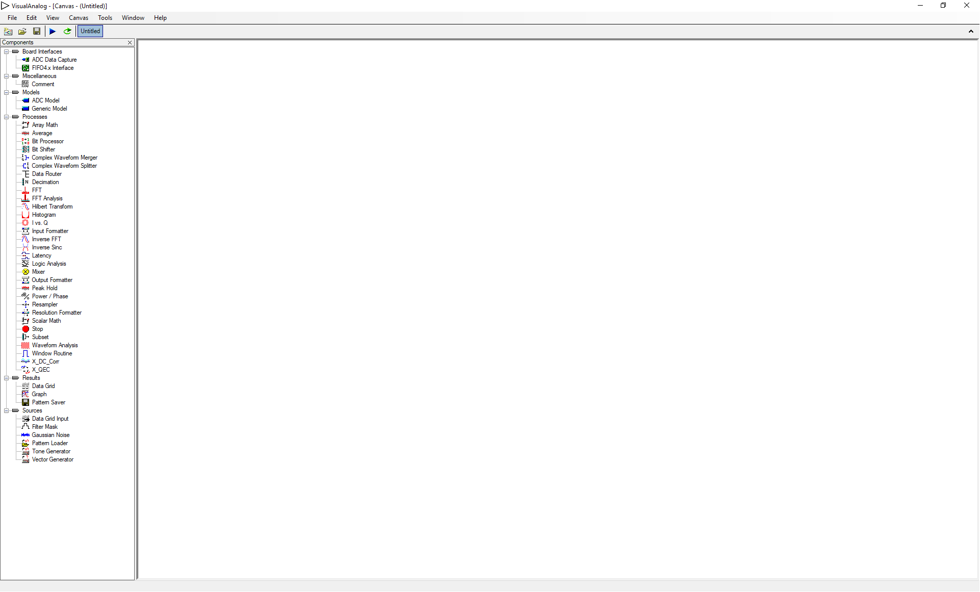
Open the file "AnalogMAX_DAQ1_Capture.vac" via "File → Open...". The window should look like Figure 1312.
Scroll Title anchor Figure12Figure 12 title Figure 12: VisualAnalog AnalogMAX_DAQ1_Capture.vac loaded Scroll Ignore draw.io Diagram border true viewerToolbar true fitWindow false diagramName VisualAnalog_File_loaded simpleViewer false width 600 diagramWidth 1921 revision 1 Scroll Only 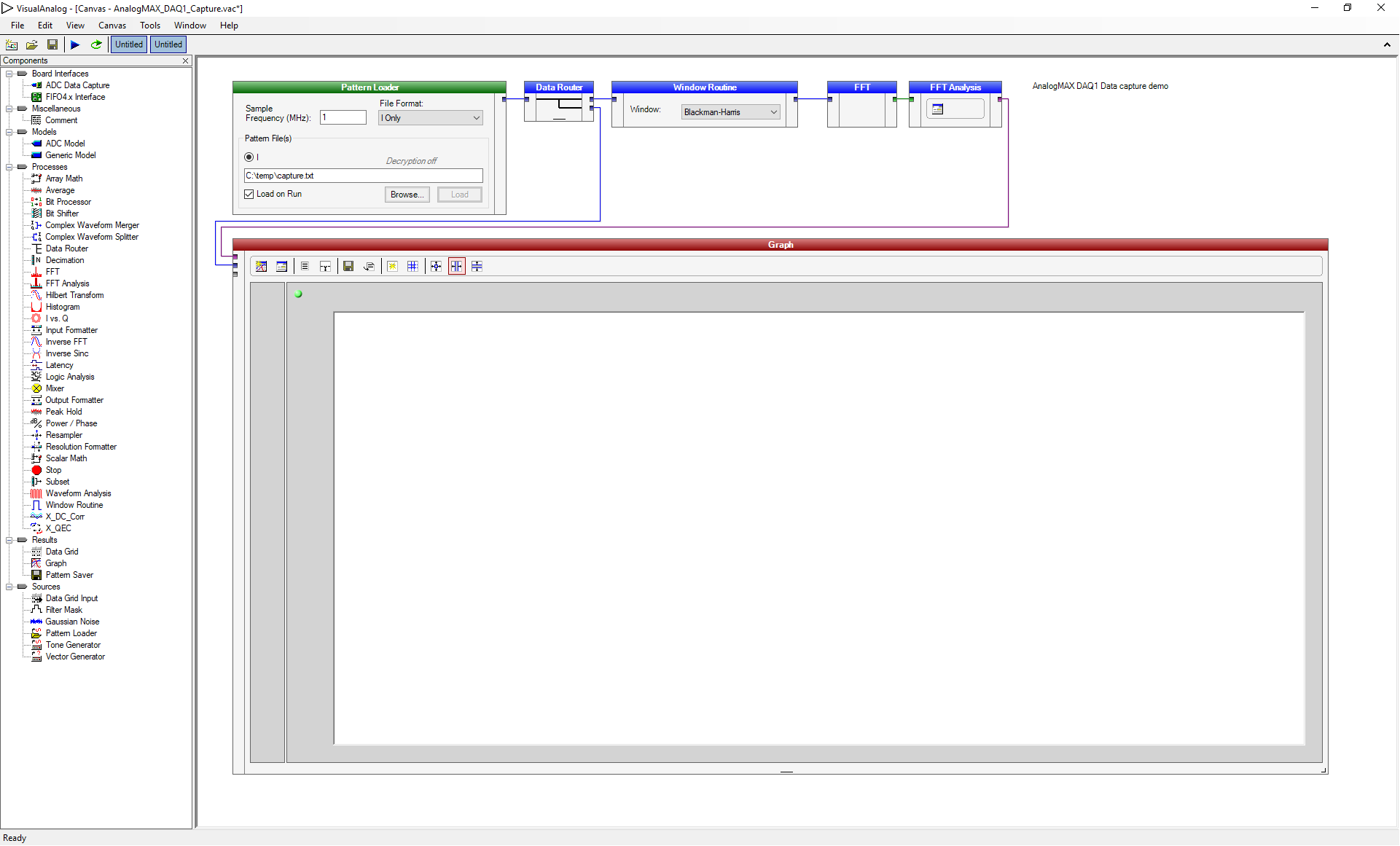
- Then change the Sample Frequency in the "Pattern Loader" to 0.5 MHz as shown in Figure 1113.
Scroll Title anchor Figure13Figure 13 title Figure 13: VisualAnalog Sample Frequency changed Scroll Ignore draw.io Diagram border true viewerToolbar true fitWindow false diagramName VisualAnalog_Frequency_Changed simpleViewer false width 600 diagramWidth 1921 revision 1 Scroll Only 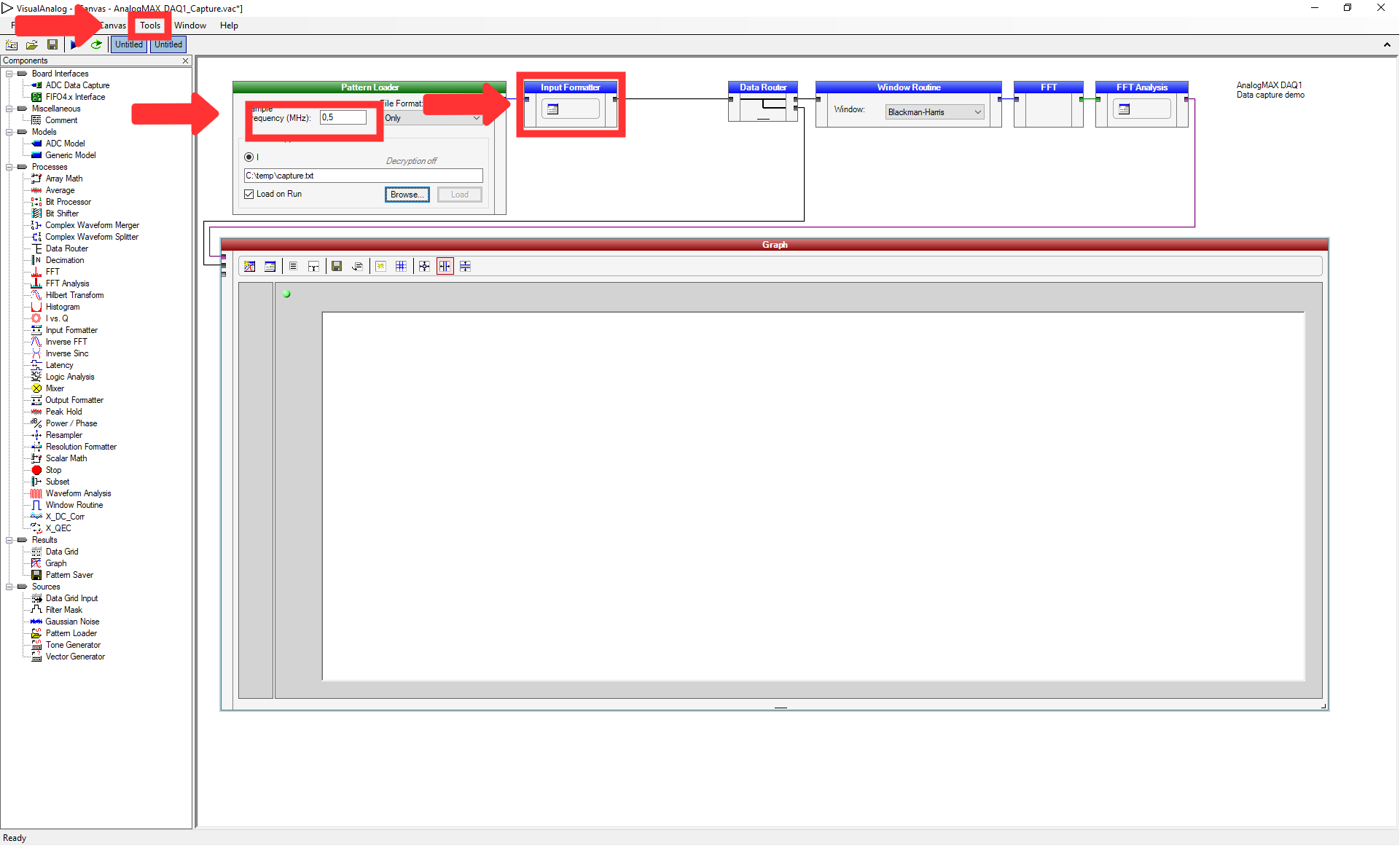
- Press "Tools → External Tools..." to prepare the usage of the adcapture.exe.
- Click "Add" in the opened window and insert the name "adcapture" in the "Display Text". Select the file "adcapture.exe" after using the button "Browse..." for the "File Name" and insert "COM20,115200 1024 c:\temp\capture.txt 7" for the "Arguments". The parameters are the COM port (COM port 20 in our case), the baud rate, the number of samples, the location to store the data and a value to adjust the system. Then, click on "Ok".
- Launch adcapture.exe and after completion click run to update the screen.
- Select the above inserted tool by selecting "Tools → adcapture".
A window shows the activity of the tool "adcapture", as visible in Figure 14.
Scroll Title anchor Figure14Figure 14 title Figure 14: Adcapture.exe output Scroll Ignore draw.io Diagram border true viewerToolbar true fitWindow false diagramName adcapture_exe simpleViewer false width diagramWidth 980 revision 1 Scroll Only 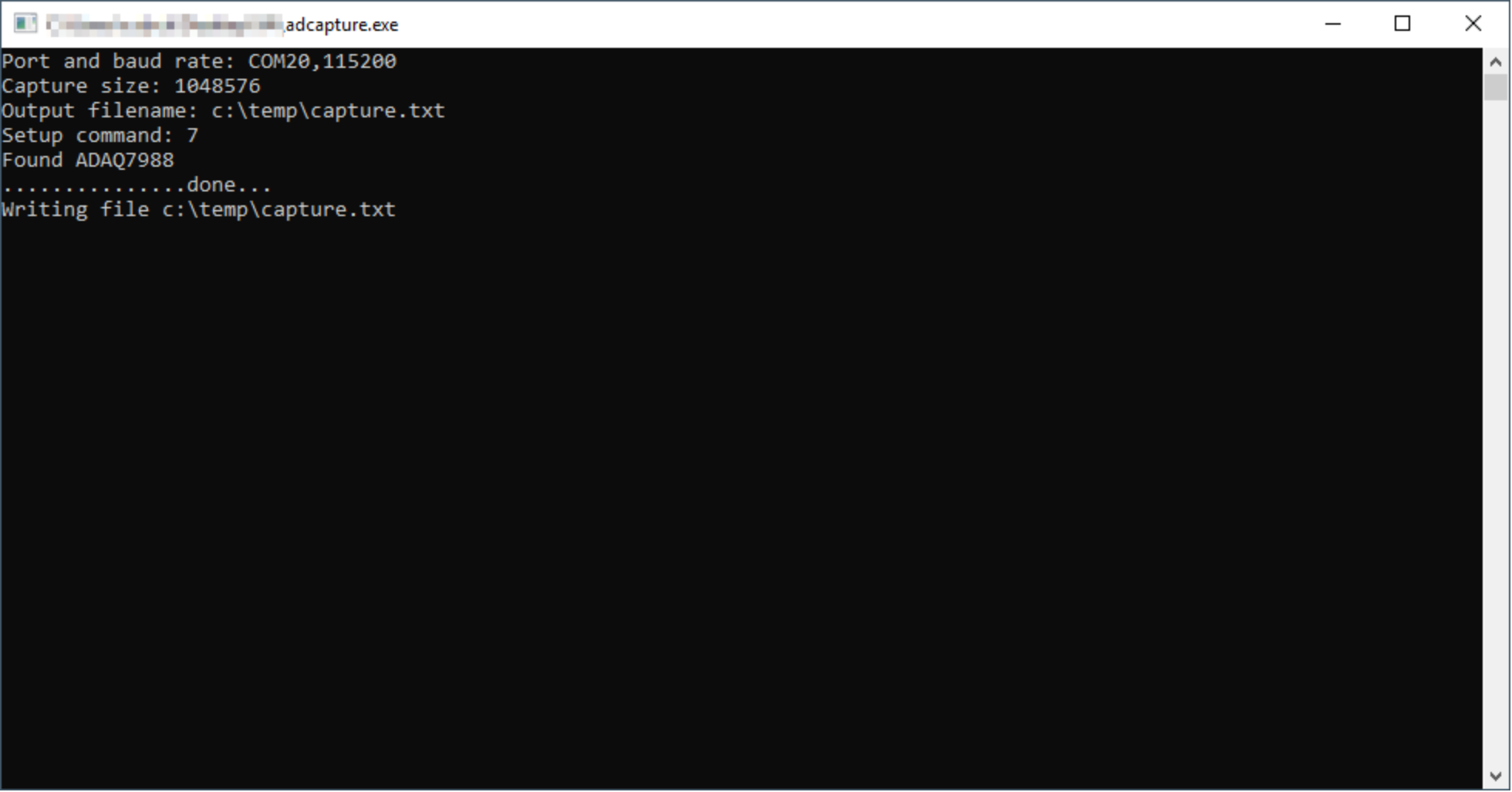
Then, using "F5" or "Canvas → Run" uses the information to create the graph in the previous window, as visible in Figure 1615.
Scroll Title anchor Figure15Figure 15 title Figure 15: VisualAnalog data interpretation Scroll Ignore draw.io Diagram border true viewerToolbar true fitWindow false diagramName VisualAnalog_Results simpleViewer false width 600 diagramWidth 1921 revision 1 Scroll Only 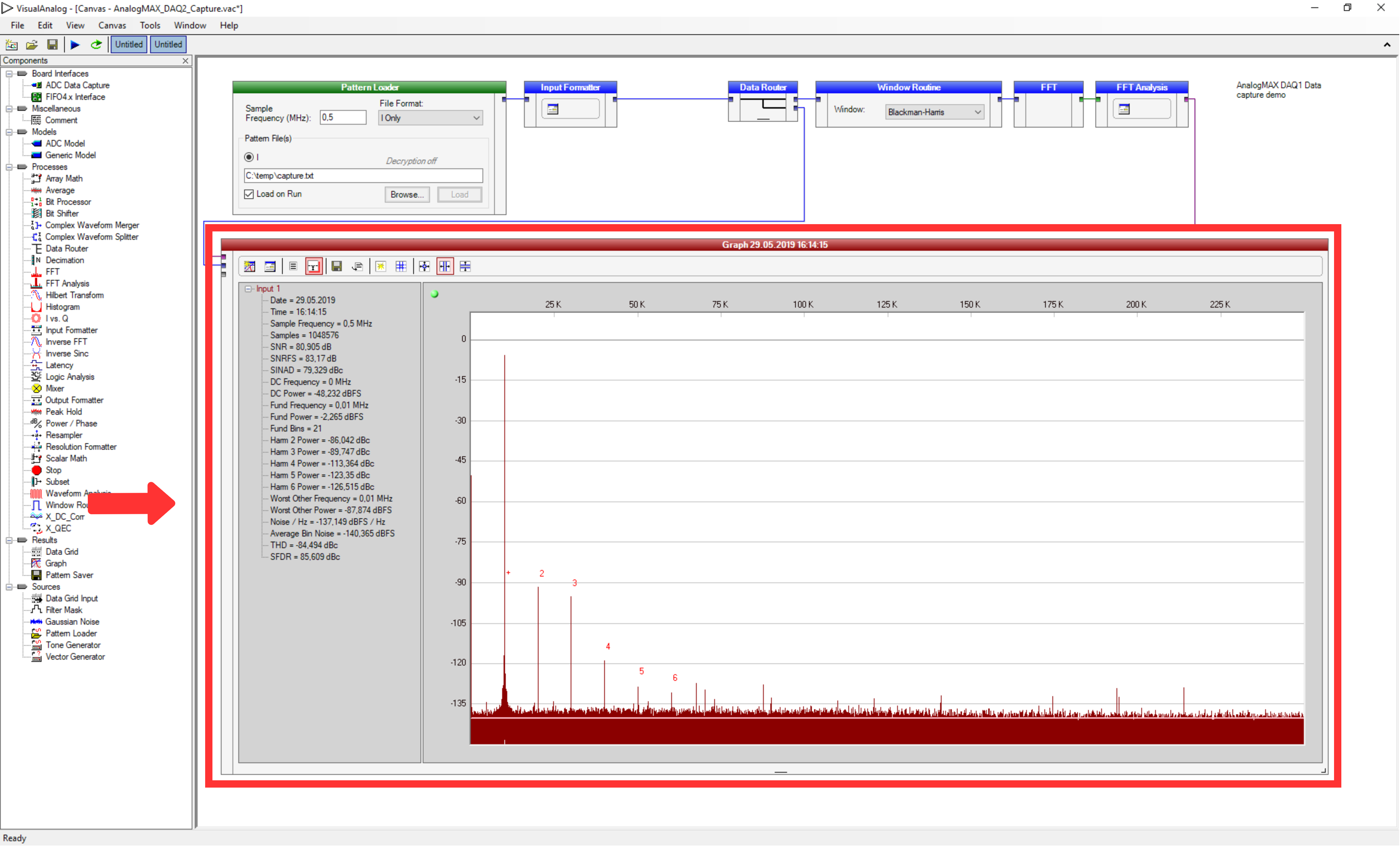
Overview
Content Tools