Module: TRM Name always "TE Series Name" +TRM Example: "TE0728 TRM"
Carrier: TRM Name usually "TEB Series Name" +TRM Example: "TEB0728 TRM"
HTML
<!--
Template Revision 1.64
(HTML comments will be not displayed in the document, no need to remove them. For Template/Skeleton changes, increase Template Revision number. So we can check faster, if the TRM style is up to date).
-->
HTML
<!--
General Notes:
If some section is CPLD firmware dependent, make a note and if available link to the CPLD firmware description. It's in the TE shop download area in the corresponding module -> revision -> firmware folder.
-->
HTML
<!--
General Notes:
Designate all graphics and pictures with a number and a description. For example "Figure 1: TE07xx-xx Block Diagram" or "Table 1: Initial delivery state". "Figure x" and "Table x" have to be formatted to bold.
-->
Scroll pdf ignore
Table of Contents
Table of Contents
Overview
...
 tables have all same width (web max 1200px and pdf full page(640px), flexible width or fix width on menu for single column can be used as before) -->
<style>
.wrapped{
  width: 100% !important;
  max-width: 1200px !important;
 }
</style>
Page properties
hidden
true
id
Comments
Important General Note:
If some section is configurable and depends on Firmware, please refer to the addition page (for example CPLD). If not available, add note, that this part is configurable
Designate all graphics and pictures with a number and a description, Use "Scroll Title" macro
Use "Scroll Title" macro for pictures and table labels. Figure number must be set manually at the moment (automatically enumeration is planned by scrollPDF)
Figure template:
Scroll Title
anchor
Figure_anchorname
title
Text
Scroll Ignore
Create DrawIO object here: Attention if you copy from other page, objects are only linked.
Scroll Only
image link to the generate DrawIO PNG file of this page. This is a workaround until scroll pdf export bug is fixed
Table template:
Layout macro can be use for landscape of large tables
Scroll Title
anchor
Table_tablename
title
Text
Scroll Table Layout
orientation
portrait
sortDirection
ASC
repeatTableHeaders
default
style
widths
sortByColumn
1
sortEnabled
false
cellHighlighting
true
Example
Comment
1
2
The anchors of the Scroll Title should be named consistant across TRMs. A incomplete list of examples is given below
<type>_<main section>_<name>
type: Figure, Table
main section:
"OV" for Overview
"SIP" for Signal Interfaces and Pins,
"OBP" for On board Peripherals,
"PWR" for Power and Power-On Sequence,
"B2B" for Board to Board Connector,
"TS" for Technical Specification
"VCP" for Variants Currently in Production
"RH" for Revision History
name: custom, some fix names, see below
Fix names:
"Figure_OV_BD" for Block Diagram
"Figure_OV_MC" for Main Components
"Table_OV_IDS" for Initial Delivery State
"Table_PWR_PC" for Power Consumption
"Figure_PWR_PD" for Power Distribution
"Figure_PWR_PS" for Power Sequence
"Figure_PWR_PM" for Power Monitoring
"Table_PWR_PR" for Power Rails
"Table_PWR_BV" for Bank Voltages
"Table_TS_AMR" for Absolute_Maximum_Ratings
"Table_TS_ROC" for Recommended_Operating_Conditions
"Figure_TS_PD" for Physical_Dimensions
"Table_VCP_SO" for TE_Shop_Overview
"Table_RH_HRH" for Hardware_Revision_History
"Figure_RH_HRN" for Hardware_Revision_Number
"Table_RH_DCH" for Document_Change_History
Use Anchor in the document: add link macro and add "#<anchorname>
Refer to Anchror from external : <page url>#<pagename without space characters>-<anchorname>
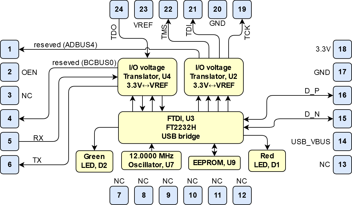
Arrow USB Programmer2 SMD module is a FT2232H based JTAG programmer supported by Intel Quartus. It's designed as Surface-mount module and have to be fitted on the target board in Surface Mount Technology. Furthermore, there is also an UART interface available and two I/O-pins reserved for future use.
For carrier or stand-alone boards use subsection for every connector type (add designator on description, not on the subsection title), for example:
SD
USB
ETH
FMC
...
For modules which needs carrier use only classes and refer to B2B connector if more than one is used, for example
JTAG
UART
I2C
MGT
...
Board to Board (B2B)
JTAG module pin assignment.
Scroll Title
anchor
Table_SIP_B2B
title
General PL I/O to B2B connectors information
Scroll Table Layout
orientation
portrait
sortDirection
ASC
repeatTableHeaders
default
style
widths
sortByColumn
1
sortEnabled
false
cellHighlighting
true
Module Pinout
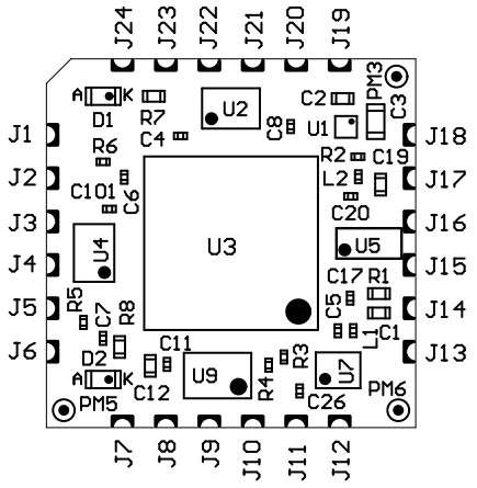
Mechanical drawing below shows the positions of the signal pins on the PCB of the module labeled with designators J1 ... J24. Followed by pin description table.
Image Removed
...
Pin Designator
Signal
Module Direction
...
1
reserved for future use
out
...
2
OEN (enable data transmitting), low active
in
...
3
Do not connect (reserved for future use)
-
...
4
reserved for future use
out
...
5
UART RX
in
...
6
UART TX
out
...
7...
...
13
Do not connect (reserved for future use)
-
...
14
USB-VBUS (USB Host supply voltage)
in
...
15
USB Data -
bidir
...
16
USB Data +
...
17
GND
-
...
18
3.3V output voltage from module
out
...
19
TCK
out
...
20
GND
-
...
21
TDI
out
...
22
TMS
out
...
23
VREF (Reference I/O-voltage from target board for JTAG and UART)
in
...
24
TDO
in
...
USB Interface
The USB interface is provided by the FTDI FT2232H IC. The entire USB protocol is handled on chip and compatible to USB 2.0 High Speed (480 MBps) and Full Speed (12 MBps).
...
FTDI FT2232H IC
FTDI FT2232H IC (U3) is used in MPPSE Mode for JTAG, Channel B is available as UART. FT2232H EEPROM is programmed with Arrow Programmer2 Identificator to be recognized by the support library for Quartus.
...
On-board LEDs indicating UART and JTAG activity:
Scroll Title
anchor
Table_OBP_LED
title
On-board LEDs
Scroll Table Layout
orientation
portrait
sortDirection
ASC
repeatTableHeaders
default
style
widths
sortByColumn
1
sortEnabled
false
cellHighlighting
true
Designator
Color
...
Connected to
Active Level
Note
D2
Green
U3-48; U3-49
low
UART activity (BCBUS3 and BCBUS4)
D1
Red
U3-20
low
JTAG activity (ADBUS7)
Table 2: On-board LEDs.
Power
Power supply of the adapter board
Arrow Programmer2 is powered via USB_VBUS rail.
Power Distribution Dependencies
Scroll Title
anchor
Figure_PWR_PD
title
Power Distribution
Scroll Ignore
draw.io Diagram
border
false
viewerToolbar
true
fitWindow
false
diagramDisplayName
lbox
false
revision
5
diagramName
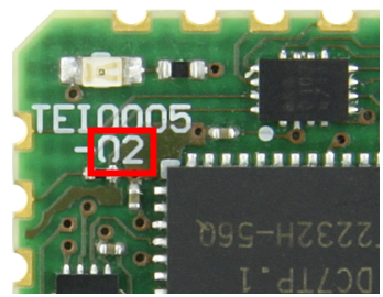
PD_TEI0005-02
simpleViewer
false
width
links
auto
tbstyle
top
diagramWidth
470
Scroll Only
Image Added
Power Rails
Scroll Title
anchor
Table_PWR_PR
title
Module power rails.
Scroll Table Layout
orientation
portrait
sortDirection
ASC
repeatTableHeaders
default
style
widths
sortByColumn
1
sortEnabled
false
cellHighlighting
true
Power Rail Name
Pad
Direction
Notes
USB_VBUS
14
IN
VREF
23
IN
3.3V
18
OUT
LDO output generated from USB_VBUS. Do not supply this rail external
Technical Specifications
Absolute Maximum Ratings
Scroll Title
anchor
Table_TS_AMR
title
PS absolute maximum ratings
Scroll Table Layout
orientation
portrait
sortDirection
ASC
repeatTableHeaders
default
style
widths
sortByColumn
1
sortEnabled
false
cellHighlighting
true
Parameter
Min
Max
Units
Reference Document
USB VBUS
4.75
5.25
V
USB 2.0 Specification
VREF
-0.5
4.6
V
Nexperia 74AVCH4T245 data sheet
Voltage on I/O pins
-0.5
4.6
V
Nexperia 74AVCH4T245 data sheet
Storage temperature
-55
+85
°C
LED LTST-C191KRKT
...
Table 3: Absolute maximum ratings.
Recommended Operating Conditions
Scroll Title
anchor
Table_TS_ROC
title
Recommended operating conditions.
Scroll Table Layout
orientation
portrait
sortDirection
ASC
repeatTableHeaders
default
style
widths
sortByColumn
1
sortEnabled
false
cellHighlighting
true
...
Parameter
Min
Max
Units
Reference Document
USB VBUS
4.75
5.25
V
USB 2.0 Specification
VREF
0.8
3.6
V
Nexperia 74AVCH4T245 data sheet (VCCB)
Voltage on I/O pins
0
VREF
V
Nexperia 74AVCH4T245 data sheet
Operating temperature
-40
+85
°C
FTDI FT2232H data sheet
...
Table 4: Recommended operating conditions.
...
Industrial grade: -40°C to +85°C.
Arrow Programmer2 can be used within industrial temperature range.
...
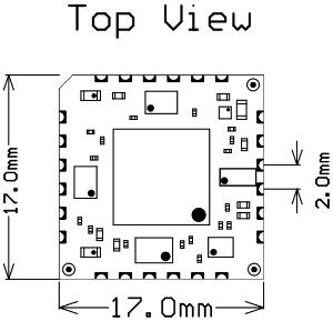
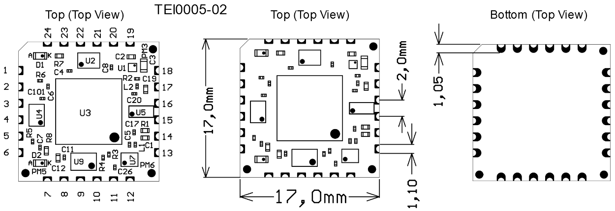
Module size: 17.0mm × 17.0mm. Please download the assembly diagram for exact numbers.
PCB thickness: ca. 1.2mm
Highest part on the PCB is 1mm, the overall hight of the module is up to 2.4mm max.
All dimensions are given in millimeters.
Image Removed
Figure 3: Physical dimensions drawing.
Page properties
hidden
true
id
Comments
In 'Physical Dimension' section, top and bottom view of module must be inserted, information regarding physical dimensions can be obtained through webpage for product in Shop.Trenz, (Download> Documents> Assembly part) for every SoM.
For Example: for Module TE0728, Physical Dimension information can be captured by snipping tools from the link below: