Page History
| Page properties | ||||
|---|---|---|---|---|
| ||||
Template Revision 2.7 - on construction Design Name always "TE Series Name" + Design name, for example "TE0720 Test Board" |
| HTML |
|---|
<!-- Template Revision 1.0 Basic Notes - export PDF to download, if vivado revision is changed! - Template is for different design and SDSoC and examples, remove unused or wrong description! --> |
| Scroll Only (inline) |
|---|
Online version of this manual and other related documents can be found at https://wiki.trenz-electronic.de/display/PD/Trenz+Electronic+Documentation |
| Scroll pdf ignore | ||||
|---|---|---|---|---|
Table of contents
|
Overview
| HTML |
|---|
<!--
General Design description
--> |
Example show, how to reconfigure SI5338 with MCS and monitor CLK. Additional MicroBlaze is add for Hello TE0741 example.
Key Features
| HTML |
|---|
<!--
Add Basic Key Features of the design (should be tested)
--> |
| Excerpt |
|---|
|
Revision History
| HTML |
|---|
<!--
- Add changes from design
- Export PDF to download, if vivado revision is changed!
--> |
...
TE0841-test_board_noprebuilt-vivado_2017.4-build_11_20180621164459.zip
TE0841-test_board-vivado_2017.4-build_11_20180621164432.zip
...
- REV02 Board parts
- new SI5338 configuration (default REV02)
- change xilisf_v5_9 for N25Q512A11G1240E support
- Some changes on block design
...
- initial release
Release Notes and Know Issues
| HTML |
|---|
<!--
- add known Design issues and general Notes for the current revision
--> |
...
Requirements
Software
| HTML |
|---|
<!--
Add needed external Software
--> |
...
Hardware
| HTML |
|---|
<!--
Hardware Support
--> |
Basic description of TE Board Part Files is available on TE Board Part Files.
Complete List is available on <design name>/board_files/*_board_files.csv
Design supports following modules:
...
Design supports following carriers:
...
Additional HW Requirements:
...
Content
| HTML |
|---|
<!--
Remove unused content
--> |
For general structure and of the reference design, see Project Delivery - Xilinx devices
Design Sources
...
tables have all same width (web max 1200px and pdf full page(640px), flexible width or fix width on menu for single column can be used as before) -->
<style>
.wrapped{
  width: 100% !important;
  max-width: 1200px !important;
 }
</style> |
| Page properties | ||||||||||||||||||||||||||||||||||||||||
|---|---|---|---|---|---|---|---|---|---|---|---|---|---|---|---|---|---|---|---|---|---|---|---|---|---|---|---|---|---|---|---|---|---|---|---|---|---|---|---|---|
| ||||||||||||||||||||||||||||||||||||||||
Important General Note:
|
| Scroll pdf ignore | ||||
|---|---|---|---|---|
Table of contents
|
Overview
| Page properties | ||||
|---|---|---|---|---|
| ||||
Notes :
|
Example show, how to reconfigure SI5338 with MCS and monitor CLK. Additional MicroBlaze with Linux example.
Refer to http://trenz.org/te0841-info for the current online version of this manual and other available documentation.
Key Features
| Page properties | ||||
|---|---|---|---|---|
| ||||
Notes :
|
| Excerpt |
|---|
|
Revision History
| Page properties | ||||
|---|---|---|---|---|
| ||||
Notes :
|
| Scroll Title | ||||||||||||||||||||||||||||||||||||||
|---|---|---|---|---|---|---|---|---|---|---|---|---|---|---|---|---|---|---|---|---|---|---|---|---|---|---|---|---|---|---|---|---|---|---|---|---|---|---|
| ||||||||||||||||||||||||||||||||||||||
|
Release Notes and Know Issues
| Page properties | ||||
|---|---|---|---|---|
| ||||
Notes :
|
| Scroll Title | ||||||||||||||||||||||||||
|---|---|---|---|---|---|---|---|---|---|---|---|---|---|---|---|---|---|---|---|---|---|---|---|---|---|---|
| ||||||||||||||||||||||||||
|
Requirements
Software
| Page properties | ||||
|---|---|---|---|---|
| ||||
Notes :
|
| Scroll Title | ||||||||||||||||||||||||||||||
|---|---|---|---|---|---|---|---|---|---|---|---|---|---|---|---|---|---|---|---|---|---|---|---|---|---|---|---|---|---|---|
| ||||||||||||||||||||||||||||||
|
Hardware
| Page properties | ||||
|---|---|---|---|---|
| ||||
Notes :
|
Basic description of TE Board Part Files is available on TE Board Part Files.
Complete List is available on <design name>/board_files/*_board_files.csv
Design supports following modules:
| Scroll Title | ||||||||||||||||||||||||||||||||||||||||||||||||||||||||||||||||||||||||||||||||||||||||||||||||||||||||||||||||||||||||||||||||||||||||||||||||||||||||||||||||||
|---|---|---|---|---|---|---|---|---|---|---|---|---|---|---|---|---|---|---|---|---|---|---|---|---|---|---|---|---|---|---|---|---|---|---|---|---|---|---|---|---|---|---|---|---|---|---|---|---|---|---|---|---|---|---|---|---|---|---|---|---|---|---|---|---|---|---|---|---|---|---|---|---|---|---|---|---|---|---|---|---|---|---|---|---|---|---|---|---|---|---|---|---|---|---|---|---|---|---|---|---|---|---|---|---|---|---|---|---|---|---|---|---|---|---|---|---|---|---|---|---|---|---|---|---|---|---|---|---|---|---|---|---|---|---|---|---|---|---|---|---|---|---|---|---|---|---|---|---|---|---|---|---|---|---|---|---|---|---|---|---|---|---|
| ||||||||||||||||||||||||||||||||||||||||||||||||||||||||||||||||||||||||||||||||||||||||||||||||||||||||||||||||||||||||||||||||||||||||||||||||||||||||||||||||||
|
Design supports following carriers:
| Scroll Title | ||||||||||||||||||||||||||||||
|---|---|---|---|---|---|---|---|---|---|---|---|---|---|---|---|---|---|---|---|---|---|---|---|---|---|---|---|---|---|---|
| ||||||||||||||||||||||||||||||
|
Additional HW Requirements:
| Scroll Title | ||||||||||||||||||||||||||
|---|---|---|---|---|---|---|---|---|---|---|---|---|---|---|---|---|---|---|---|---|---|---|---|---|---|---|
| ||||||||||||||||||||||||||
|
Content
| Page properties | ||||
|---|---|---|---|---|
| ||||
Notes :
|
For general structure and of the reference design, see Project Delivery - Xilinx devices
Design Sources
| Scroll Title | ||||||||||||||||||||||||||||||
|---|---|---|---|---|---|---|---|---|---|---|---|---|---|---|---|---|---|---|---|---|---|---|---|---|---|---|---|---|---|---|
| ||||||||||||||||||||||||||||||
|
Additional Sources
| Scroll Title | ||||||||||||||||||||||||
|---|---|---|---|---|---|---|---|---|---|---|---|---|---|---|---|---|---|---|---|---|---|---|---|---|
| ||||||||||||||||||||||||
|
Prebuilt
| Page properties | |||||||||||||||||||||||||||||||||||||||||||||||||||||||||||||||||||
|---|---|---|---|---|---|---|---|---|---|---|---|---|---|---|---|---|---|---|---|---|---|---|---|---|---|---|---|---|---|---|---|---|---|---|---|---|---|---|---|---|---|---|---|---|---|---|---|---|---|---|---|---|---|---|---|---|---|---|---|---|---|---|---|---|---|---|---|
| |||||||||||||||||||||||||||||||||||||||||||||||||||||||||||||||||||
Notes :
|
| Scroll Title | |||||||||||||||||||||||||||||||||||||||||||||||||||
|---|---|---|---|---|---|---|---|---|---|---|---|---|---|---|---|---|---|---|---|---|---|---|---|---|---|---|---|---|---|---|---|---|---|---|---|---|---|---|---|---|---|---|---|---|---|---|---|---|---|---|---|
| |||||||||||||||||||||||||||||||||||||||||||||||||||
|
Download
Reference Design is only usable with the specified Vivado/SDK/PetaLinux/SDx version. Do never use different Versions of Xilinx Software for the same Project.
| HTML |
|---|
<!--
Add correct path:https://shop.trenz-electronic.de/en/Download/?path=Trenz_Electronic/TE0803/Reference_Design/2017.1/Starterkit
--> |
Reference Design is available on:
Design Flow
| Page properties | ||||
|---|---|---|---|---|
| ||||
Notes :
|
| Note |
|---|
Reference Design is available with and without prebuilt files. It's recommended to use TE prebuilt files for first lunch. |
Trenz Electronic provides a tcl based built environment based on Xilinx Design Flow.
See also:Xilinx Development Tools
The Trenz Electronic FPGA Reference Designs are TCL-script based project. Command files for execution will be generated with "_create_win_setup.cmd" on Windows OS and "_create_linux_setup.sh" on Linux OS.
TE Scripts are only needed to generate the vivado project, all other additional steps are optional and can also executed by Xilinx Vivado/SDK GUI. For currently Scripts limitations on Win and Linux OS see: Project Delivery Currently limitations of functionality
- _create_win_setup.cmd/_create_linux_setup.sh and follow instructions on shell:
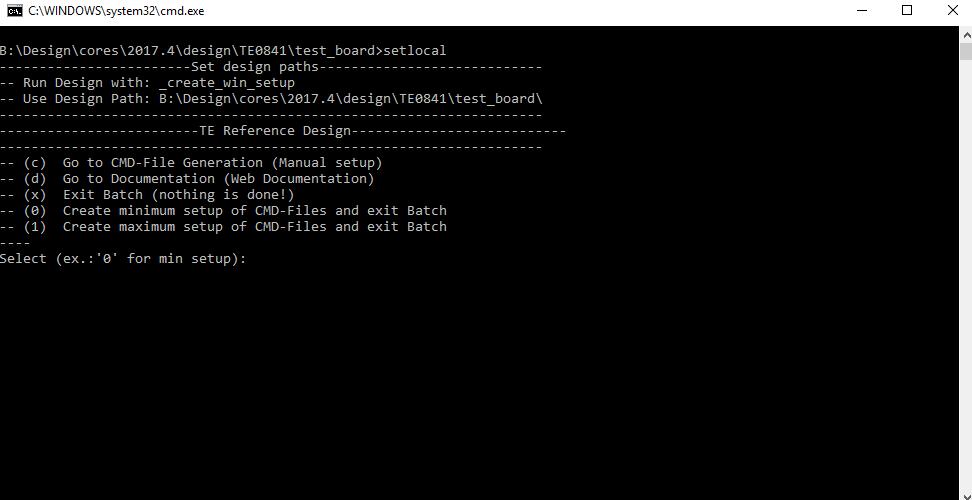
- Press 0 and enter to start "Module Selection Guide"
- (optional Win OS) Generate Virtual Drive or use short directory for the reference design (for example x:\<design name>)
- Create Project (follow instruction of the product selection guide), settings file will be configured automatically during this process
- optional for manual changes) Select correct device and Xilinx install path on "design_basic_settings.cmd" and create Vivado project with "vivado_create_project_guimode.cmd"
Note: Select correct one, see TE Board Part Files
- optional for manual changes) Select correct device and Xilinx install path on "design_basic_settings.cmd" and create Vivado project with "vivado_create_project_guimode.cmd"
- Create XSA and export to prebuilt folder
- Run on Vivado TCL: TE::hw_build_design -export_prebuilt
Note: Script generate design and export files into \prebuilt\hardware\<short dir>. Use GUI is the same, except file export to prebuilt folder
- Run on Vivado TCL: TE::hw_build_design -export_prebuilt
- Create Linux (uboot.elf and image.ub) with exported XSA
- XSA is exported to "prebuilt\hardware\<short name>"
Note: HW Export from Vivado GUI create another path as default workspace. - Create Linux images on VM, see PetaLinux KICKstart
- Use TE Template from /os/petalinux
Important Note: Select correct Flash partition offset on petalinux-config: Subsystem Auto HW Settings → Flash Settings, FPGA+Boot+bootenv=0xA00000 (increase automatically generate Boot partition), increase image size to A:, see TE0841 Test Board#Config
- Use TE Template from /os/petalinux
- XSA is exported to "prebuilt\hardware\<short name>"
- Add Linux files (uboot.elf and image.ub) to prebuilt folder
"prebuilt\os\petalinux\<ddr size>" or "prebuilt\os\petalinux\<short name>"
Notes: Scripts select "prebuilt\os\petalinux\<short name>", if exist, otherwise "prebuilt\os\petalinux\<DDR size>" of the selected device
- Generate Programming Files with Vitis
- Run on Vivado TCL: TE::sw_run_vitis -all
Note: Depending of PC performance this can take several minutes. Scripts generate applications and bootable files, which are defined in "sw_lib\apps_list.csv" and open Vitis - (alternative) Start Vitis with Vivado GUI or start with TE Scripts on Vivado TCL: TE::sw_run_vitis
Note: TCL scripts generate also platform project, this must be done manuelly in case GUI is used. See Vitis
- Run on Vivado TCL: TE::sw_run_vitis -all
- Copy "\prebuilt\software\<short name>\srec_spi_bootloader.elf" into "\firmware\microblaze_0\"
- (optional) Copy "\\workspace\sdk\scu\Release\scu.elf" into "\firmware\microblaze_mcs_0\"
- Regenerate Vivado Project or Update Bitfile only with "srec_spi_bootloader.elf" and "scu_te0841.elf"
Launch
Programming
| Page properties | ||||
|---|---|---|---|---|
| ||||
Note:
|
| Note |
|---|
Check Module and Carrier TRMs for proper HW configuration before you try any design. |
Xilinx documentation for programming and debugging: Vivado/SDK/SDSoC-Xilinx Software Programming and Debugging
Get prebuilt boot binaries
- _create_win_setup.cmd/_create_linux_setup.sh and follow instructions on shell
- Press 0 and enter to start "Module Selection Guide"
- Select assembly version
- Validate selection
- Select Create and open delivery binary folder
Note: Folder (<project foler>/_binaries_<Artikel Name>) with subfolder (boot_<app name>) for different applications will be generated
QSPI
- Connect JTAG and power on PCB
- (if not done) Select correct device and Xilinx install path on "design_basic_settings.cmd" and create Vivado project with "vivado_create_project_guimode.cmd" or open with "vivado_open_project_guimode.cmd", if generated.
- Type on Vivado Console: TE::pr_program_flash -swapp u-boot
Note: Alternative use SDK or setup Flash on Vivado manually
optional "TE::pr_program_flash -swapp hello_te0841" possible - Reboot (if not done automatically)
SD
Not used on this Example.
JTAG
- Connect JTAG and power on PCB
- Open Vivado HW Manager
- Program FPGA with Bitfile from "prebuilt\hardware\<short dir>"
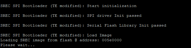
- Note SREC Bootloader try to find application on flash, this will stop, if Flash is empty.
Usage
- Prepare HW like described on section 54395771
- Connect UART USB (most cases same as JTAG)
- Power on PCB
Note: FPGA Loads Bitfile from Flash,MCS Firmware configure SI5338 and starts Microblaze, SREC Bootloader from Bitfile Firmware loads U-Boot into DDR (This takes a while), U-boot loads Linux from QSPI Flash into DDR - Open Serial Console (e.g. putty)
- Speed: 9600
- COM Port: Win OS, see device manager, Linux OS see dmesg |grep tty (UART is *USB1)
Boot process takes a while, please wait.
Linux
Note: Linux boot process is slower on Microblaze.
- Open Serial Console (e.g. putty)
- Speed: 9600
- COM Port: Win OS, see device manager, Linux OS see dmesg |grep tty (UART is *USB1)
- Linux Console:
Note: Wait until Linux boot finished For Linux Login use:- User Name: root
- Password: root
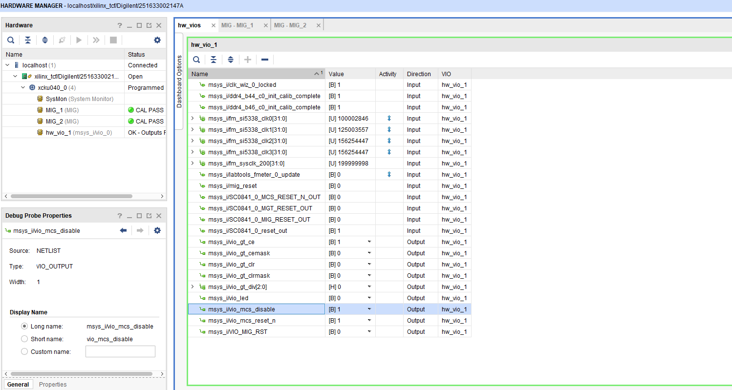
Vivado HW Manager:
- Open Vivado HW-Manager and add VIO signal to dashboard (*.ltx located on prebuilt folder).
- Set radix from VIO signals (fm_si...) to unsigned integer.
Note: Frequency Counter is inaccurate and displayed unit is Hz - SI will be configured with MCS firmware, default all off on PCB REV01, PCB REV02 SI5338 will be preconfigured.
- LED control via VIO
- MGT CLK Freq can be changed over BUFG_GT control signals divider
- MCS Reset possible via VIO
- MIG Reset is possible over VIO
- MCS can be disabled over VIO (For PCB REV01 MCS is enabled, fpr PCB REV02 MCS is disabled by default VIO)
- Set radix from VIO signals (fm_si...) to unsigned integer.
| Scroll Title | ||||
|---|---|---|---|---|
| ||||
 |
System Design - Vivado
| Page properties | ||||
|---|---|---|---|---|
| ||||
Note:
|
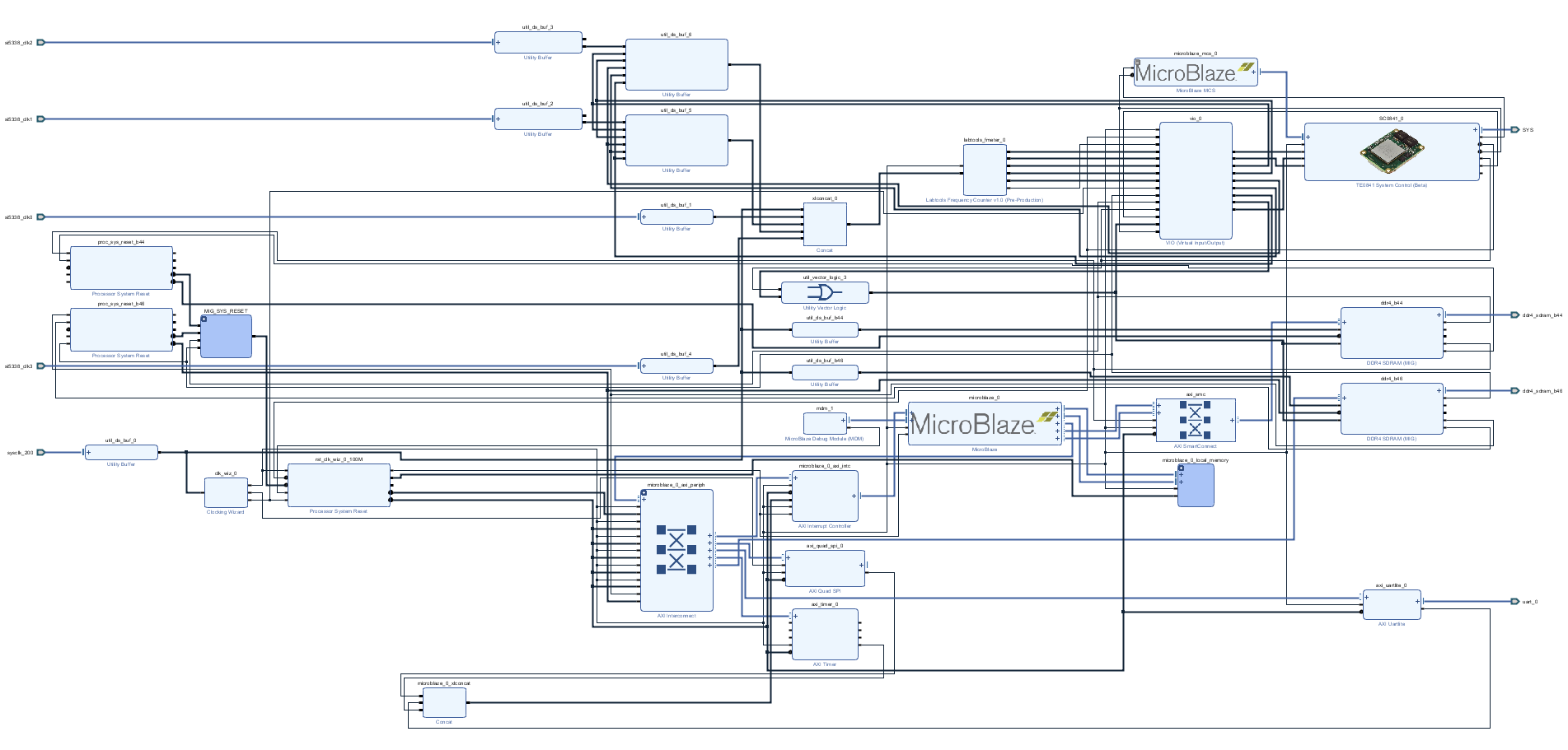
Block Design
| Scroll Title | ||||
|---|---|---|---|---|
| ||||
*Note: REV01 has SI5338 programming default enabled and REV02 default disabled. SI5338 of REV02 is preprogrammed |
Constrains
Basic module constrains
| Code Block | ||||
|---|---|---|---|---|
| ||||
set_property BITSTREAM.GENERAL.COMPRESS TRUE [current_design]
set_property BITSTREAM.CONFIG.CONFIGRATE 69 [current_design]
set_property CFGBVS GND [current_design]
set_property CONFIG_VOLTAGE 1.8 [current_design]
set_property CONFIG_MODE SPIx4 [current_design]
set_property BITSTREAM.CONFIG.SPI_32BIT_ADDR YES [current_design]
set_property BITSTREAM.CONFIG.SPI_BUSWIDTH 4 [current_design]
set_property BITSTREAM.CONFIG.M1PIN PULLNONE [current_design]
set_property BITSTREAM.CONFIG.M2PIN PULLNONE [current_design]
set_property BITSTREAM.CONFIG.M0PIN PULLNONE [current_design]

set_property BITSTREAM.CONFIG.USR_ACCESS TIMESTAMP [current_design] |
Design specific constrain
| Code Block | ||||||
|---|---|---|---|---|---|---|
| ||||||
set_property CLOCK_DEDICATED_ROUTE BACKBONE [get_pins -hier -filter {NAME =~ */u_ddr4_infrastructure/gen_mmcme*.u_mmcme_adv_inst/CLKIN1}]
create_clock -name ddr4_0_clk -period 4.95 [get_pins */ddr4_0/*/u_ddr4_infrastructure/gen_mmcme*.u_mmcme_adv_inst/CLKIN1]
create_clock -name ddr4_1_clk -period 4.95 [get_pins */ddr4_1/*/u_ddr4_infrastructure/gen_mmcme*.u_mmcme_adv_inst/CLKIN1]
set_property BITSTREAM.CONFIG.UNUSEDPIN PULLUP [current_design |
| Code Block | ||||||
|---|---|---|---|---|---|---|
| ||||||
# You must provide all the delay numbers
# CCLK delay is 0.1, 6.7 ns min/max for ultra-scale devices; refer Data sheet
# Consider the max delay for worst case analysis
set cclk_delay 6.7
create_generated_clock -name clk_sck -source [get_pins -hierarchical *axi_quad_spi_0/ext_spi_clk] -edges {3 5 7} -edge_shift [list $cclk_delay $cclk_delay $cclk_delay] [get_pins -hierarchical *USRCCLKO]
set_multicycle_path -setup -from clk_sck -to [get_clocks -of_objects [get_pins -hierarchical */ext_spi_clk]] 2
set_multicycle_path -hold -end -from clk_sck -to [get_clocks -of_objects [get_pins -hierarchical */ext_spi_clk]] 1
set_multicycle_path -setup -start -from [get_clocks -of_objects [get_pins -hierarchical */ext_spi_clk]] -to clk_sck 2
set_multicycle_path -hold -from [get_clocks -of_objects [get_pins -hierarchical */ext_spi_clk]] -to clk_sck 1
# Max delay constraints are used to instruct the tool to place IP near to STARTUPE3 primitive.
# If needed adjust the delays appropriately
set_max_delay -datapath_only -from [get_pins -hier {*STARTUP*_inst/DI[*]}] 1.000
set_max_delay -datapath_only -from [get_clocks clk_out2_msys_clk_wiz_0_0] -to [get_pins -hier *STARTUP*_inst/USRCCLKO] 1.000
#set_max_delay -datapath_only -from [get_clocks clk_out2_msys_clk_wiz_0_0] -to [get_pins -hier *STARTUP*_inst/DO[*] {*STARTUP*_inst/DTS[*]}] 1.000
set_max_delay -datapath_only -from [get_clocks clk_out2_msys_clk_wiz_0_0] -to [get_pins -hier *STARTUP*_inst/DO[*]] 1.000
set_max_delay -datapath_only -from [get_clocks clk_out2_msys_clk_wiz_0_0] -to [get_pins -hier *STARTUP*_inst/DTS[*]] 1.000
|
| Code Block | ||||||
|---|---|---|---|---|---|---|
| ||||||
set_false_path -from [get_clocks {msys_i/util_ds_buf_5/U0/BUFG_GT_O[0]}] -to [get_clocks -of_objects [get_pins msys_i/clk_wiz_0/inst/mmcme3_adv_inst/CLKOUT0]]
set_false_path -from [get_clocks {msys_i/util_ds_buf_6/U0/BUFG_GT_O[0]}] -to [get_clocks -of_objects [get_pins msys_i/clk_wiz_0/inst/mmcme3_adv_inst/CLKOUT0]]
set_false_path -from [get_clocks -of_objects [get_pins msys_i/clk_wiz_0/inst/mmcme3_adv_inst/CLKOUT0]] -to [get_clocks {msys_i/util_ds_buf_6/U0/BUFG_GT_O[0]}]
set_false_path -from [get_clocks -of_objects [get_pins msys_i/clk_wiz_0/inst/mmcme3_adv_inst/CLKOUT0]] -to [get_clocks {msys_i/util_ds_buf_5/U0/BUFG_GT_O[0]}]

set_false_path -from [get_clocks -of_objects [get_pins msys_i/clk_wiz_0/inst/mmcme3_adv_inst/CLKOUT0]] -to [get_clocks {msys_i/util_ds_buf_1/U0/IBUF_OUT[0]}]
set_false_path -from [get_clocks -of_objects [get_pins msys_i/clk_wiz_0/inst/mmcme3_adv_inst/CLKOUT0]] -to [get_clocks {msys_i/util_ds_buf_4/U0/IBUF_OUT[0]}]
set_false_path -from [get_clocks {msys_i/util_ds_buf_0/U0/IBUF_OUT[0]}] -to [get_clocks -of_objects [get_pins msys_i/clk_wiz_0/inst/mmcme3_adv_inst/CLKOUT0]]
set_false_path -from [get_clocks {msys_i/util_ds_buf_1/U0/IBUF_OUT[0]}] -to [get_clocks -of_objects [get_pins msys_i/clk_wiz_0/inst/mmcme3_adv_inst/CLKOUT0]]
set_false_path -from [get_clocks {msys_i/util_ds_buf_4/U0/IBUF_OUT[0]}] -to [get_clocks -of_objects [get_pins msys_i/clk_wiz_0/inst/mmcme3_adv_inst/CLKOUT0]]
|
Software Design - Vitis
| Page properties | ||||
|---|---|---|---|---|
| ||||
Note:
|
For SDK project creation, follow instructions from:
Application
| Page properties | ||||
|---|---|---|---|---|
| ||||
---------------------------------------------------------- FPGA Example scuMCS Firmware to configure SI5338 and Reset System. srec_spi_bootloaderTE modified 2019.2 SREC Bootloader to load app or second bootloader from flash into DDR Descriptions:
xilisf_v5_11TE modified 2019.2 xilisf_v5_11
---------------------------------------------------------- Zynq Example: zynq_fsblTE modified 2019.2 FSBL General:
Module Specific:
zynq_fsbl_flashTE modified 2019.2 FSBL General:
ZynqMP Example: ---------------------------------------------------------- zynqmp_fsblTE modified 2019.2 FSBL General:
Module Specific:
zynqmp_fsbl_flashTE modified 2019.2 FSBL General:
zynqmp_pmufwXilinx default PMU firmware. ---------------------------------------------------------- General Example: hello_te0820Hello TE0820 is a Xilinx Hello World example as endless loop instead of one console output. u-bootU-Boot.elf is generated with PetaLinux. SDK/HSI is used to generate Boot.bin. |
Template location: ./sw_lib/sw_apps/
scu
MCS Firmware to configure SI5338 and Reset System.
srec_spi_bootloader
TE modified 2019.2 SREC
Bootloader to load app or second bootloader from flash into DDR
Descriptions:
- Modified Files: blconfig.h, bootloader.c
- Changes:
- Add some console outputs and changed bootloader read address.
- Add bugfix for 2018.2 qspi flash (some reinitialisation)
SREC SPI Bootloader
Modified Xilinx SREC Bootloader. Changes: Correct flash typ and SRec Start address, some additional console outputs, see source code
Changed xilisf_v5_9 to support N25Q512_1V8 for SREC (changes on xilisf.c and xilisf_intelstm.h)
Template location: \sw_lib\sw_apps\srec_spi_bootloader
\sw_lib\sw_services\xilisf_v5_9
xilisf_v5_14
TE modified 2019.2 xilisf_v5_14
- Changed default Flash type to 5.
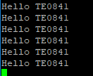
hello_te0841
Hello TE0841 is a Xilinx Hello World example as endless loop instead of one console output.
u-boot
U-Boot.elf is generated with PetaLinux. SDK/HSI is used to generate u-boot.srec. Vivado to generate *.mcs
Software Design - PetaLinux
| Page properties | ||||
|---|---|---|---|---|
| ||||
Note:
|
Description currently not available.
Config
Start with petalinux-config or petalinux-config --get-hw-description
Changes:
- SUBSYSTEM_FLASH_AXI_QUAD_SPI_0_BANKLESS_PART0_SIZE = 0x6E0000
- SUBSYSTEM_FLASH_AXI_QUAD_SPI_0_BANKLESS_PART1_SIZE = 0x300000
- SUBSYSTEM_FLASH_AXI_QUAD_SPI_0_BANKLESS_PART2_SIZE = 0x20000
- SUBSYSTEM_FLASH_AXI_QUAD_SPI_0_BANKLESS_PART3_SIZE = 0xA00000
- (Set kernel flash Address to 0xA00000 and Kernel size to 0xA00000)
U-Boot
Start with petalinux-config -c u-boot
Changes:
- No changes.
Change platform-top.h:
| Code Block | ||
|---|---|---|
| ||
Device Tree
| Code Block | ||
|---|---|---|
| ||
Kernel
Start with petalinux-config -c kernel
Changes:
- No changes.
Rootfs
Start with petalinux-config -c rootfs
Changes:
- # CONFIG_dropbear is not set
- # CONFIG_dropbear-dev is not set
- # CONFIG_dropbear-dbg is not set
- # CONFIG_packagegroup-core-ssh-dropbear is not set
- # CONFIG_packagegroup-core-ssh-dropbear-dev is not set
- # CONFIG_packagegroup-core-ssh-dropbear-dbg is not set
- # CONFIG_imagefeature-ssh-server-dropbear is not set
Applications
No additional application.
Additional Software
| Page properties | ||||
|---|---|---|---|---|
| ||||
| Note: |
SI5338
File location <design name>/misc/Si5338/Si5338-*.slabtimeproj
General documentation how you work with these project will be available on Si5338
Appx. A: Change History and Legal Notices
Document Change History
To get content of older revision got to "Change History" of this page and select older document revision number.
| Page properties | ||||
|---|---|---|---|---|
| ||||
|
| Scroll Title | ||||||||||||||||||
|---|---|---|---|---|---|---|---|---|---|---|---|---|---|---|---|---|---|---|
| ||||||||||||||||||
|
Additional Sources
...
Prebuilt
| HTML |
|---|
<!--

<table width="100%">
<tr> <th>File                                 </th> <th>File-Extension</th>  <th>Description                                                                              </th> </tr>
<tr> <td>BIF-File                             </td> <td>*.bif         </td>  <td>File with description to generate Bin-File                                               </td> </tr>
<tr> <td>BIN-File                             </td> <td>*.bin         </td>  <td>Flash Configuration File with Boot-Image (Zynq-FPGAs)                                    </td> </tr>
<tr> <td>BIT-File                             </td> <td>*.bit         </td>  <td>FPGA Configuration File                                                                  </td> </tr>
<tr> <td>DebugProbes-File                     </td> <td>*.ltx         </td>  <td>Definition File for Vivado/Vivado Labtools Debugging Interface                           </td> </tr>
<tr> <td>Debian SD-Image                      </td> <td>*.img         </td>  <td>Debian Image for SD-Card                                                                </td> </tr>
<tr> <td>Diverse Reports                      </td> <td>  ---         </td>  <td>Report files in different formats                                                        </td> </tr>
<tr> <td>Hardware-Platform-Specification-Files</td> <td>*.hdf         </td>  <td>Exported Vivado Hardware Specification for SDK/HSI                                       </td> </tr>
<tr> <td>LabTools Project-File                </td> <td>*.lpr         </td>  <td>Vivado Labtools Project File                                                             </td> </tr>
<tr> <td>MCS-File                             </td> <td>*.mcs         </td>  <td>Flash Configuration File with Boot-Image (MicroBlaze or FPGA part only)                  </td> </tr>
<tr> <td>MMI-File                             </td> <td>*.mmi         </td>  <td>File with BRAM-Location to generate MCS or BIT-File with *.elf content (MicroBlaze only) </td> </tr>
<tr> <td>OS-Image                             </td> <td>*.ub          </td>  <td>Image with Linux Kernel (On Petalinux optional with Devicetree and RAM-Disk)             </td> </tr>
<tr> <td>Software-Application-File            </td> <td>*.elf         </td>  <td>Software Application for Zynq or MicroBlaze Processor Systems                            </td> </tr>
<tr> <td>SREC-File                            </td> <td>*.srec        </td>  <td>Converted Software Application for MicroBlaze Processor Systems                          </td> </tr>
</table>
-->
|
...
File
...
File-Extension
...
Description
...
MCS-File
...
*.mcs
...
Flash Configuration File with Boot-Image (MicroBlaze or FPGA part only)
...
MMI-File
...
*.mmi
...
File with BRAM-Location to generate MCS or BIT-File with *.elf content (MicroBlaze only)
...
*.srec
...
Converted Software Application for MicroBlaze Processor Systems
Download
Reference Design is only usable with the specified Vivado/SDK/PetaLinux/SDx version. Do never use different Versions of Xilinx Software for the same Project.
| HTML |
|---|
<!--
Add correct path:https://shop.trenz-electronic.de/en/Download/?path=Trenz_Electronic/TE0803/Reference_Design/2017.1/Starterkit
--> |
Reference Design is available on:
Design Flow
| HTML |
|---|
<!--
Basic Design Steps
Add/ Remove project specific
--> |
| Note |
|---|
Reference Design is available with and without prebuilt files. It's recommended to use TE prebuilt files for first lunch. |
Trenz Electronic provides a tcl based built environment based on Xilinx Design Flow.
See also:Xilinx Development Tools
The Trenz Electronic FPGA Reference Designs are TCL-script based project. Command files for execution will be generated with "_create_win_setup.cmd" on Windows OS and "_create_linux_setup.sh" on Linux OS.
TE Scripts are only needed to generate the vivado project, all other additional steps are optional and can also executed by Xilinx Vivado/SDK GUI. For currently Scripts limitations on Win and Linux OS see: Project Delivery Currently limitations of functionality
- _create_win_setup.cmd/_create_linux_setup.sh and follow instructions on shell:
- Press 0 and enter for minimum setup
- (optional Win OS) Generate Virtual Drive or use short directory for the reference design (for example x:\<design name>)
- Create Project
- Select correct device and Xilinx install path on "design_basic_settings.cmd" and create Vivado project with "vivado_create_project_guimode.cmd"
Note: Select correct one, see TE Board Part Files
- Select correct device and Xilinx install path on "design_basic_settings.cmd" and create Vivado project with "vivado_create_project_guimode.cmd"
- Create HDF and export to prebuilt folder
- Run on Vivado TCL: TE::hw_build_design -export_prebuilt
Note: Script generate design and export files into \prebuilt\hardware\<short dir>. Use GUI is the same, except file export to prebuilt folder
- Run on Vivado TCL: TE::hw_build_design -export_prebuilt
- Generate MCS Firmware (optional):
- Create SDK Project with TE Scripts on Vivado TCL: TE::sw_run_sdk
- Create "SCU" application
Note: Select MCS Microblaze and SCU Application - Select Release Built
- Regenerate App
- Generate Programming Files with HSI/SDK
- Run on Vivado TCL: TE::sw_run_hsi
Note: Scripts generate applications and bootable files, which are defined in "sw_lib\apps_list.csv" - (alternative) Start SDK with Vivado GUI or start with TE Scripts on Vivado TCL: TE::sw_run_sdk
Note: See SDK Projects
- Run on Vivado TCL: TE::sw_run_hsi
- Copy "\prebuilt\software\<short name>\srec_spi_bootloader.elf" into "\firmware\microblaze_0\"
- (optional) Copy "\\workspace\sdk\scu\Release\scu.elf" into "\firmware\microblaze_mcs_0\"
- Regenerate Vivado Project or Update Bitfile only with "srec_spi_bootloader.elf" and "scu.elf"
- Generate MCS file with Bitfile and application for SREC Bootloader
- Create SDK Project with TE Scripts on Vivado TCL: TE::sw_run_hsi
Note: SREC convertion from *.elf to *.srec will be done by scripts, alternative use SDK, see SDK Projects
- Create SDK Project with TE Scripts on Vivado TCL: TE::sw_run_hsi
Launch
Programming
| HTML |
|---|
<!--
Description of Block Design, Constrains...
BD Pictures from Export...
--> |
| Note |
|---|
Check Module and Carrier TRMs for proper HW configuration before you try any design. |
Xilinx documentation for programming and debugging: Vivado/SDK/SDSoC-Xilinx Software Programming and Debugging
QSPI
- Connect JTAG and power on PCB
- (if not done) Select correct device and Xilinx install path on "design_basic_settings.cmd" and create Vivado project with "vivado_create_project_guimode.cmd" or open with "vivado_open_project_guimode.cmd", if generated.
- Type on Vivado Console: TE::pr_program_flash_mcsfile -swapp hello_te0841
Note: Alternative use SDK or setup Flash on Vivado manually - Reboot (if not done automatically)
SD
Not used on this Example.
JTAG
- Connect JTAG and power on PCB
- Open Vivado HW Manager
- Program FPGA with Bitfile from "prebuilt\hardware\<short dir>"
- Note SREC Bootloader try to find application on flash, this will stop, if Flash is empty.
Usage
- Prepare HW like described on section Programming
- Connect UART USB (most cases same as JTAG)
- Power on PCB
Note: FPGA Loads Bitfile from Flash,MCS Firmware configure SI5338 and starts MicroBlaze, MicroBlaze SREC Bootloader loads Hello TE0781 from Flash into RAM and starts application. Example will be run on UART console.
Do not reboot, if Bitfile programming over JTAG is used as programming method.
UART
Open Serial Console (e.g. putty)
- Speed: 9600
- COM Port: Win OS, see device manager, Linux OS see dmesg |grep tty (UART is *USB1)
Vivado HW Manager:
- Open Vivado HW-Manager and add VIO signal to dashboard (*.ltx located on prebuilt folder).
- Set radix from VIO signals (fm_si...) to unsigned integer.
Note: Frequency Counter is inaccurate and displayed unit is Hz - SI will be configured with MCS firmware, default all off on PCB REV01, PCB REV02 SI5338 will be preconfigured.
- LED control via VIO
- MGT CLK Freq can be changed over BUFG_GT control signals divider
- MCS Reset possible via VIO
- MIG Reset is possible over VIO
- MCS can be disabled over VIO (For PCB REV01 MCS is enabled, fpr PCB REV02 MCS is disabled by default VIO)
- Set radix from VIO signals (fm_si...) to unsigned integer.
System Design - Vivado
| HTML |
|---|
<!--
Description of Block Design, Constrains...
BD Pictures from Export...
--> |
Block Design
Constrains
Basic module constrains
| Code Block | ||||
|---|---|---|---|---|
| ||||
set_property BITSTREAM.GENERAL.COMPRESS TRUE [current_design]
set_property BITSTREAM.CONFIG.CONFIGRATE 69 [current_design]
set_property CFGBVS GND [current_design]
set_property CONFIG_VOLTAGE 1.8 [current_design]
set_property CONFIG_MODE SPIx4 [current_design]
set_property BITSTREAM.CONFIG.SPI_32BIT_ADDR YES [current_design]
set_property BITSTREAM.CONFIG.SPI_BUSWIDTH 4 [current_design]
set_property BITSTREAM.CONFIG.M1PIN PULLNONE [current_design]
set_property BITSTREAM.CONFIG.M2PIN PULLNONE [current_design]
set_property BITSTREAM.CONFIG.M0PIN PULLNONE [current_design]

set_property BITSTREAM.CONFIG.USR_ACCESS TIMESTAMP [current_design] |
Design specific constrain
| Code Block | ||||||
|---|---|---|---|---|---|---|
| ||||||
set_property CLOCK_DEDICATED_ROUTE BACKBONE [get_pins -hier -filter {NAME =~ */u_ddr4_infrastructure/gen_mmcme*.u_mmcme_adv_inst/CLKIN1}]
create_clock -name ddr4_0_clk -period 4.95 [get_pins */ddr4_0/*/u_ddr4_infrastructure/gen_mmcme*.u_mmcme_adv_inst/CLKIN1]
create_clock -name ddr4_1_clk -period 4.95 [get_pins */ddr4_1/*/u_ddr4_infrastructure/gen_mmcme*.u_mmcme_adv_inst/CLKIN1]
set_property BITSTREAM.CONFIG.UNUSEDPIN PULLUP [current_design |
| Code Block | ||||||
|---|---|---|---|---|---|---|
| ||||||
# You must provide all the delay numbers
# CCLK delay is 0.1, 6.7 ns min/max for ultra-scale devices; refer Data sheet
# Consider the max delay for worst case analysis
set cclk_delay 6.7
create_generated_clock -name clk_sck -source [get_pins -hierarchical *axi_quad_spi_0/ext_spi_clk] -edges {3 5 7} -edge_shift [list $cclk_delay $cclk_delay $cclk_delay] [get_pins -hierarchical *USRCCLKO]
set_multicycle_path -setup -from clk_sck -to [get_clocks -of_objects [get_pins -hierarchical */ext_spi_clk]] 2
set_multicycle_path -hold -end -from clk_sck -to [get_clocks -of_objects [get_pins -hierarchical */ext_spi_clk]] 1
set_multicycle_path -setup -start -from [get_clocks -of_objects [get_pins -hierarchical */ext_spi_clk]] -to clk_sck 2
set_multicycle_path -hold -from [get_clocks -of_objects [get_pins -hierarchical */ext_spi_clk]] -to clk_sck 1
# Max delay constraints are used to instruct the tool to place IP near to STARTUPE3 primitive.
# If needed adjust the delays appropriately
set_max_delay -datapath_only -from [get_pins -hier {*STARTUP*_inst/DI[*]}] 1.000
set_max_delay -datapath_only -from [get_clocks clk_out2_msys_clk_wiz_0_0] -to [get_pins -hier *STARTUP*_inst/USRCCLKO] 1.000
#set_max_delay -datapath_only -from [get_clocks clk_out2_msys_clk_wiz_0_0] -to [get_pins -hier *STARTUP*_inst/DO[*] {*STARTUP*_inst/DTS[*]}] 1.000
set_max_delay -datapath_only -from [get_clocks clk_out2_msys_clk_wiz_0_0] -to [get_pins -hier *STARTUP*_inst/DO[*]] 1.000
set_max_delay -datapath_only -from [get_clocks clk_out2_msys_clk_wiz_0_0] -to [get_pins -hier *STARTUP*_inst/DTS[*]] 1.000
|
| Code Block | ||||||
|---|---|---|---|---|---|---|
| ||||||
set_false_path -from [get_clocks {msys_i/util_ds_buf_5/U0/BUFG_GT_O[0]}] -to [get_clocks -of_objects [get_pins msys_i/clk_wiz_0/inst/mmcme3_adv_inst/CLKOUT0]]
set_false_path -from [get_clocks {msys_i/util_ds_buf_6/U0/BUFG_GT_O[0]}] -to [get_clocks -of_objects [get_pins msys_i/clk_wiz_0/inst/mmcme3_adv_inst/CLKOUT0]]
set_false_path -from [get_clocks -of_objects [get_pins msys_i/clk_wiz_0/inst/mmcme3_adv_inst/CLKOUT0]] -to [get_clocks {msys_i/util_ds_buf_6/U0/BUFG_GT_O[0]}]
set_false_path -from [get_clocks -of_objects [get_pins msys_i/clk_wiz_0/inst/mmcme3_adv_inst/CLKOUT0]] -to [get_clocks {msys_i/util_ds_buf_5/U0/BUFG_GT_O[0]}]

set_false_path -from [get_clocks -of_objects [get_pins msys_i/clk_wiz_0/inst/mmcme3_adv_inst/CLKOUT0]] -to [get_clocks {msys_i/util_ds_buf_1/U0/IBUF_OUT[0]}]
set_false_path -from [get_clocks -of_objects [get_pins msys_i/clk_wiz_0/inst/mmcme3_adv_inst/CLKOUT0]] -to [get_clocks {msys_i/util_ds_buf_4/U0/IBUF_OUT[0]}]
set_false_path -from [get_clocks {msys_i/util_ds_buf_0/U0/IBUF_OUT[0]}] -to [get_clocks -of_objects [get_pins msys_i/clk_wiz_0/inst/mmcme3_adv_inst/CLKOUT0]]
set_false_path -from [get_clocks {msys_i/util_ds_buf_1/U0/IBUF_OUT[0]}] -to [get_clocks -of_objects [get_pins msys_i/clk_wiz_0/inst/mmcme3_adv_inst/CLKOUT0]]
set_false_path -from [get_clocks {msys_i/util_ds_buf_4/U0/IBUF_OUT[0]}] -to [get_clocks -of_objects [get_pins msys_i/clk_wiz_0/inst/mmcme3_adv_inst/CLKOUT0]]
|
Software Design - SDK/HSI
| HTML |
|---|
<!--
optional chapter
separate sections for different apps
--> |
For SDK project creation, follow instructions from:
Application
SCU
MCS Firmware to configure SI5338 and Reset System.
Template location: \sw_lib\sw_apps\scu
Hello TE0841
Xilinx Hello World example as endless loop
Template location: \sw_lib\sw_apps\hello_te0841
SREC SPI Bootloader
Modified Xilinx SREC Bootloader. Changes: Correct flash typ and SRec Start address, some additional console outputs, see source code
Changed xilisf_v5_9 to support N25Q512_1V8 for SREC (changes on xilisf.c and xilisf_intelstm.h)
Template location: \sw_lib\sw_apps\srec_spi_bootloader
\sw_lib\sw_services\xilisf_v5_9
Additional Software
| HTML |
|---|
<!--
Add Description for other Software, for example SI CLK Builder ...
--> |
SI5338
Download ClockBuilder Desktop for SI5338
- Install and start ClockBuilder
- Select SI5338
- Options → Open register map file
Note: File location <design name>/misc/Si5338/RegisterMap.txt - Modify settings
- Options → save C code header files
- Replace Header files from SCU template with generated file
Appx. A: Change History and Legal Notices
Document Change History
To get content of older revision got to "Change History" of this page and select older document revision number.
| HTML | ||||||||||||||||||||||||||
|---|---|---|---|---|---|---|---|---|---|---|---|---|---|---|---|---|---|---|---|---|---|---|---|---|---|---|
<!--
Generate new entry:
1:add new row below first
2:Copy Page Information Macro(date+user) Preview, Page Information Macro Preview
3.Update Metadate =Page Information Macro Preview+1
-->
|
...
|
...
|
...
|
...
|
Legal Notices
| Include Page | ||||
|---|---|---|---|---|
|
...
Overview
Content Tools