Page History
| Page properties | ||||||||||||||||||||||||
|---|---|---|---|---|---|---|---|---|---|---|---|---|---|---|---|---|---|---|---|---|---|---|---|---|
| ||||||||||||||||||||||||
Design Name always "TE Series Name" + Design name, for example "TEI0006 Test Board"
|
| Custom_table_size_100 |
|---|
| Page properties | ||||||||||||||||||||||||||||||||||||||||
|---|---|---|---|---|---|---|---|---|---|---|---|---|---|---|---|---|---|---|---|---|---|---|---|---|---|---|---|---|---|---|---|---|---|---|---|---|---|---|---|---|
| ||||||||||||||||||||||||||||||||||||||||
Important General Note:
|
Overview
| Scroll Ignore | ||||||||||||||
|---|---|---|---|---|---|---|---|---|---|---|---|---|---|---|
| ||||||||||||||
| Page properties | ||||
|---|---|---|---|---|
| ||||
Notes :
|
Refer to http://trenz.org/tei0022-info for the current online version of this manual and other available documentation.
Key Features
| Page properties | ||||
|---|---|---|---|---|
| ||||
Notes :
|
| Excerpt |
|---|
|
Revision History
| Page properties | ||||
|---|---|---|---|---|
| ||||
Notes:
|
| Scroll Title | ||||||||||||||||||||||||||||||||||||||
|---|---|---|---|---|---|---|---|---|---|---|---|---|---|---|---|---|---|---|---|---|---|---|---|---|---|---|---|---|---|---|---|---|---|---|---|---|---|---|
| ||||||||||||||||||||||||||||||||||||||
|
Release Notes and Know Issues
| Page properties | ||||
|---|---|---|---|---|
| ||||
Notes:
|
| Scroll Title | ||||||||||||||||||||||||||
|---|---|---|---|---|---|---|---|---|---|---|---|---|---|---|---|---|---|---|---|---|---|---|---|---|---|---|
| ||||||||||||||||||||||||||
|
Requirements
Software
| Page properties | ||||
|---|---|---|---|---|
| ||||
Notes :
|
| Scroll Title | ||||||||||||||||||||||||||
|---|---|---|---|---|---|---|---|---|---|---|---|---|---|---|---|---|---|---|---|---|---|---|---|---|---|---|
| ||||||||||||||||||||||||||
|
Hardware
| Page properties | ||||
|---|---|---|---|---|
| ||||
Notes :
|
Complete List is available on <project folder>/board_files/*_board_files.csv
Design supports following modules:
| Scroll Title | ||||||||||||||||||||||||||||||||||||
|---|---|---|---|---|---|---|---|---|---|---|---|---|---|---|---|---|---|---|---|---|---|---|---|---|---|---|---|---|---|---|---|---|---|---|---|---|
| ||||||||||||||||||||||||||||||||||||
*used as reference |
Design supports following carriers:
| Scroll Title | ||||||||||||||||||||||
|---|---|---|---|---|---|---|---|---|---|---|---|---|---|---|---|---|---|---|---|---|---|---|
| ||||||||||||||||||||||
*used as reference |
Additional HW Requirements:
| Scroll Title | ||||||||||||||||||||||||||||||||
|---|---|---|---|---|---|---|---|---|---|---|---|---|---|---|---|---|---|---|---|---|---|---|---|---|---|---|---|---|---|---|---|---|
| ||||||||||||||||||||||||||||||||
*used as reference |
Content
| Page properties | ||||
|---|---|---|---|---|
| ||||
Notes :
|
For general structure and usage of the reference design, see Project Delivery - Intel devices
Design Sources
| Scroll Title | |||||||||||||||||||||||
|---|---|---|---|---|---|---|---|---|---|---|---|---|---|---|---|---|---|---|---|---|---|---|---|
| |||||||||||||||||||||||
|
Prebuilt
| Page properties | ||||||||||||||||||||||||||||||||||||||||||||||||||||||||||||||||||
|---|---|---|---|---|---|---|---|---|---|---|---|---|---|---|---|---|---|---|---|---|---|---|---|---|---|---|---|---|---|---|---|---|---|---|---|---|---|---|---|---|---|---|---|---|---|---|---|---|---|---|---|---|---|---|---|---|---|---|---|---|---|---|---|---|---|---|
| ||||||||||||||||||||||||||||||||||||||||||||||||||||||||||||||||||
Notes :
|
| Scroll Title | ||||||||||||||||||||||||||||||||||||||||||||||
|---|---|---|---|---|---|---|---|---|---|---|---|---|---|---|---|---|---|---|---|---|---|---|---|---|---|---|---|---|---|---|---|---|---|---|---|---|---|---|---|---|---|---|---|---|---|---|
| ||||||||||||||||||||||||||||||||||||||||||||||
|
Download
Reference Design is only usable with the specified Quartus version. Do never use different versions of Quartus software for the same project.
| Page properties | ||||
|---|---|---|---|---|
| ||||
|
Reference Design is available on:
Design Flow
| Scroll Ignore | ||||||||||||||
|---|---|---|---|---|---|---|---|---|---|---|---|---|---|---|
| ||||||||||||||
| Page properties | ||||
|---|---|---|---|---|
| ||||
Notes :
|
| Note |
|---|
Reference Design is available with and without prebuilt files. It's recommended to use TE prebuilt files for first launch. |
Trenz Electronic provides a tcl based built environment based on Quartus Design Flow.
See also:
The Trenz Electronic FPGA Reference Designs are TCL-script based projects. To create a project, open a project or program a device execute "create_project_win.cmd" on Windows OS and "create_project_linux.sh" on Linux OS.
TE Scripts are only needed to generate the quartus project, all other additional steps are optional and can also executed by Intel Quartus/SDK GUI. For currently Scripts limitations on Win OS and Linux OS see: Project Delivery - Intel devices → Currently limitations of functionality
- Open create_project_win.cmd/create_project_linux.sh:
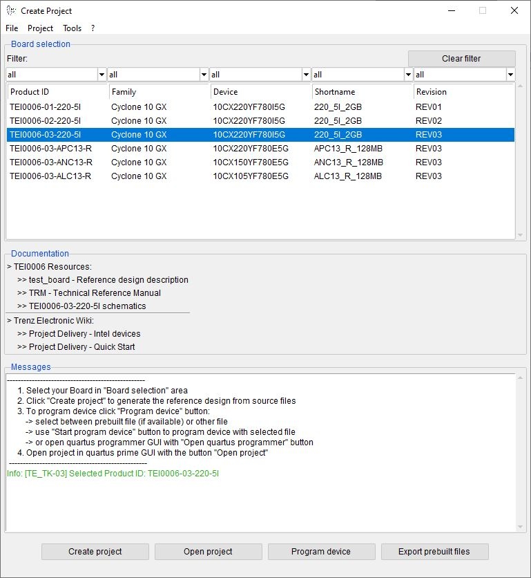
- Select Board in "Board selection"
- Click on "Create project" button to create project
- (optional for manual changes) Select correct quartus installation path in "<project folder>/settings/design_basic_settings.tcl"
- Create and configure your Yocto Linux project, see Yocto KICKstart
- Copy the generated meta-<module> folder from <project name>/os/yocto/meta-<module> to the path/to/yocto/poky/ directory
- Follow the steps from Yocto KICKstart#Create a project for an Intel FPGA device without running the 'bitbake' command
Add the generated bsp layer meta-<machine> to path/to/yocto/poky/build/conf/bblayers.conf with:
Code Block theme Midnight linenumbers true bitbake-layers add-layer ../meta-tei0022
Info Note: The generated meta-tei0022 layer depends on the meta-altera layer (for more information see: Yocto KICKstart#Used source files), so you need to add both bsp layers to bblayers.conf
Redefine the variable MACHINE with 'tei0022-<Board-Part-Short-Name>' in path/to/yocto/poky/build/conf/local.conf. The correct MACHINE name can be found in the #Hardware table.
Also define the variables INITRAMFS_IMAGE_BUNDLE and INITRAMFS_IMAGE to create a ram disk image.Code Block theme Midnight linenumbers true true sed -i '/^MACHINE/s/MACHINE/#MACHINE/g' conf/local.conf echo -e '\nMACHINE = "tei0022-<Board-Part-Short-Name>"' >> conf/local.conf echo -e '\nINITRAMFS_IMAGE_BUNDLE = "1"' >> sed -i '/^MACHINE/s/MACHINE/#MACHINE/g' conf/local.conf echo -e '\nMACHINEINITRAMFS_IMAGE = "tei0022-<Board-Part-Short-Name>te-initramfs"' >> conf/local.conf
Build the image with following command (the image recipes are located in meta-tei0022/recipes-core/images/yocto/):
Code Block theme Midnight linenumbers true bitbake tei0022te-image-minimal
- [optional] Create a debian or ubuntu rootfs with/without desktop environment for this board. For more information and instructions see: Create debian/ubuntu rootfs - Intel devices
Launch
| Scroll Ignore |
|---|
| Page properties | ||||
|---|---|---|---|---|
| ||||
Note:
|
Programming
| Note |
|---|
Check Module and Carrier TRMs for proper HW configuration before you try any design. |
SD-Boot mode
- Follow the steps described in Reference Designs with Yocto - Intel devices to copy the generated linux image to the SD card.
- Set Boot Mode to SD-Boot.
- see module TRM for correct settings
- Insert SD-Card in SD-Slot.
QSPI
Not used on this example.Option for u-boot-with-spl.sfp on QSPI flash and zimage-initramfs-<Yocto Machine Name>.bin, <Yocto Machine Name>.dtb, soc_system.rbf and extlinux/extlinux.conf on SD card
JTAG
Not used on this example.
Usage
- Prepare HW like described on section #Programming
- Connect UART USB (most cases same as JTAG)
- Power on PCB
UART
- Open Serial Console (e.g. PuTTY)
select COM Port
Info Win OS: see device manager
Linux OS: see dmesg | grep tty (UART is *USB1)
- Speed: 115200
- Press reset button
- Linux Console:
Login data:
Info Note: Wait until Linux boot finished
Code Block theme Midnight linenumbers true Username: root Password: root
You can use Linux shell now.
Code Block theme Midnight linenumbers true i2cdetect -y -r 1 (check I2C 1 Bus) udhcpc (ETH0 check) lsusb (USB check)
Monitor
- Connect the Monitor to HDMI
- Connect the Mouse+Keyboard to USB
- Press reset button
- If yocto default rootfs is used, the linux console is displayed:
Login data:
Info Note: Wait until Linux boot finished
Code Block theme Midnight linenumbers true Username: root Password: root
You can use Linux shell now.
Code Block theme Midnight linenumbers true i2cdetect -y -r 1 (check I2C 1 Bus) udhcpc (ETH0 check) lsusb (USB check)
- [optional] Ubuntu/Debian desktop will be started automatically (for more information see #Rootfs)
System Design - Quartus
| Scroll Ignore |
|---|
| Page properties | ||||
|---|---|---|---|---|
| ||||
Note:
|
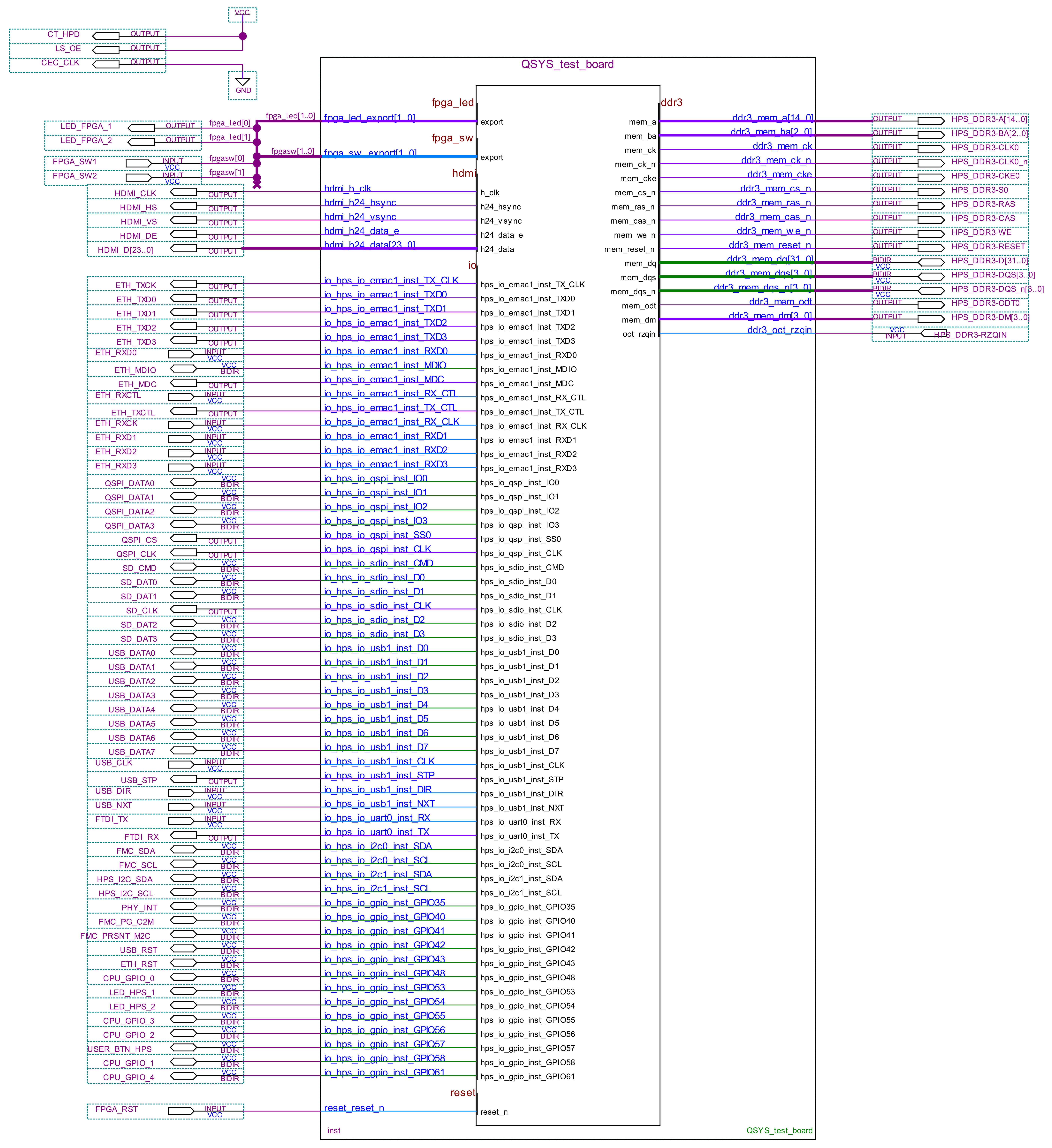
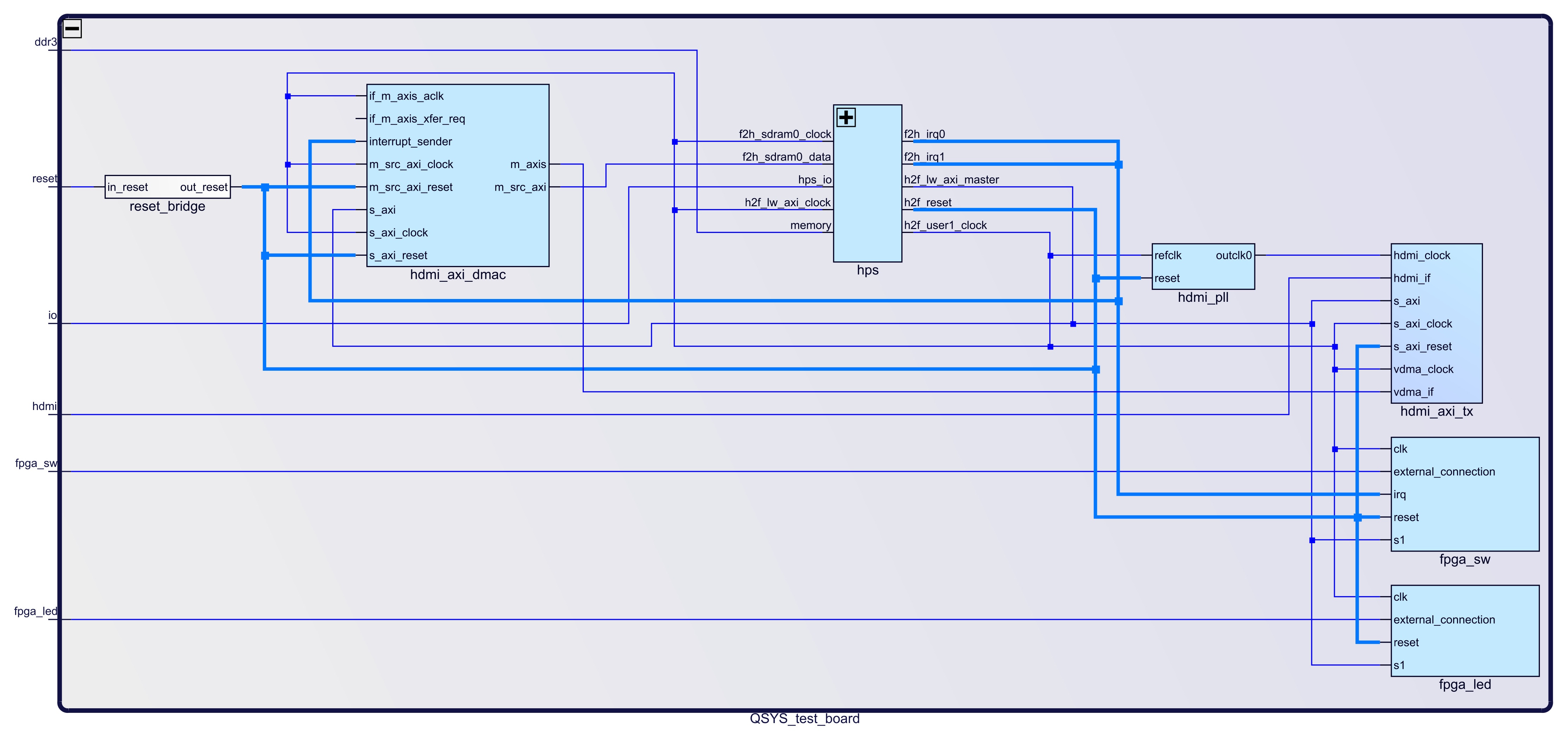
Block Design
The block designs may differ depending on the assembly variant.
| Scroll Title | ||||||
|---|---|---|---|---|---|---|
| ||||||
 |
| Scroll Title | ||||||
|---|---|---|---|---|---|---|
| ||||||
 |
HPS Interfaces
Activated interfaces:
| Type | Note |
| DDR | -- |
| EMAC1 | -- |
| QSPI | -- |
| SDMMC | -- |
| USB1 | -- |
| UART0 | -- |
| I2C0 | -- |
| I2C1 | -- |
| GPIO35 | connected to ETH PHY_INT pin |
| GPIO42 | connected to USB_RST pin |
| GPIO43 | connected to ETH_RST pin |
| GPIO48 | connected to CPU_GPIO_0 pin |
| GPIO53 | connected to LED_HPS_1 pin |
| GPIO54 | connected to LED_HPS_2 pin |
| GPIO55 | connected to CPU_GPIO_3 pin |
| GPIO56 | connected to CPU_GPIO_2 pin |
| GPIO57 | connected to USER_BTN_HPS pin |
| GPIO58 | connected to CPU_GPIO_1 pin |
| GPIO61 | connected to CPU_GPIO_4 pin |
Software Design - Yocto
| Scroll Ignore |
|---|
For Yocto installation and project creation, follow instructions from:
- Yocto KICKstart
- Create a custom BSP layer for Intel SoC or FPGA
- Create debian/ubuntu rootfs - Intel devices
U-Boot
Start with Create a custom BSP layer for Intel SoC or FPGA#Configure u-boot
File location: meta-tei0022/recipes-bsp/u-boot/
Changes:
select tei0022 board
# CONFIG_TARGET_SOCFPGA_CYCLONE5_SOCDK is not set
CONFIG_TARGET_TEI0022=y
configure bootcommand (load soc_system.rbf file into the FPGA
CONFIG_BOOTCOMMAND="load mmc 0:1 $loadaddr soc_system.rbf; fpga load 0 $loadaddr $filesize; bridge enable; run distro_bootcmd"
- enable misc_init_r function (need to call TE_read_eeprom_mac function)
CONFIG_MISC_INIT_R=y
CONFIG_MISC=y
MAC from eeprom together with uboot:
CONFIG_I2C_EEPROM=y
CONFIG_SYS_I2C_EEPROM_ADDR=0x50
CONFIG_SYS_I2C_EEPROM_BUS=1
CONFIG_SYS_EEPROM_SIZE=256
CONFIG_SYS_EEPROM_PAGE_WRITE_BITS=0
CONFIG_SYS_EEPROM_PAGE_WRITE_DELAY_MS=0
CONFIG_SYS_I2C_EEPROM_ADDR_LEN=1
CONFIG_SYS_I2C_EEPROM_ADDR_OVERFLOW=0
configure eth
- CONFIG_PHYLIB=y
CONFIG_NETDEVICES=y
CONFIG_RGMII=y
# CONFIG_MII is not set
- select device tree
- CONFIG_DEFAULT_DEVICE_TREE="tei0022_<Board Part Short Name>"
- CONFIG_DEFAULT_FDT_FILE="tei0022_<Board Part Short Name>.dtb"
Device Tree
| Code Block | ||||
|---|---|---|---|---|
| ||||
#include "socfpga_cyclone5.dtsi"
#include "dt-bindings/interrupt-controller/irq.h"
#include <dt-bindings/gpio/gpio.h>

/ {
	chosen {
		bootargs = "earlyprintk";
		stdout-path = "serial0:115200n8";
	};

	axi_dma_clk: axi_dma_clk {
		#clock-cells = <0x0>;
		compatible = "fixed-clock";
		clock-frequency = <100000000>;
		clock-output-names = "axi_dma_clock";
	};

	sys_clk: sys_clk {
		#clock-cells = <0x0>;
		compatible = "fixed-clock";
		clock-frequency = <80000000>;
		clock-output-names = "sys_clock";
	};

	hdmi_pll: hdmi_pll {
		compatible = "altr,altera_iopll-18.1";
		#clock-cells = <1>;
			hdmi_pll_outclk0: hdmi_pll_outclk0 {
			compatible = "fixed-clock";
			#clock-cells = <0>;
			clock-frequency = <148500000>;
			clock-output-names = "hdmi_pll-outclk0";
		};
	};

        vdd: regulator-vdd {
                compatible = "regulator-fixed";
                regulator-name = "fixed-supply";
                regulator-min-microvolt = <1800000>;
                regulator-max-microvolt = <1800000>;
                regulator-always-on;
        };

        vdd_3_3: regulator-vdd {
                compatible = "regulator-fixed";
                regulator-name = "fixed-supply";
                regulator-min-microvolt = <3300000>;
                regulator-max-microvolt = <3300000>;
                regulator-always-on;
        };

        vref: regulator-vref {
                compatible = "regulator-fixed";
                regulator-name = "fixed-supply";
                regulator-min-microvolt = <2500000>;
                regulator-max-microvolt = <2500000>;
                regulator-always-on;
        };

	soc {
		 i2c1: i2c@ffc05000 {
			status = "okay";
			speed-mode = <0>;
			#address-cells = <1>;
			#size-cells = <0>;

			adv7511: adv7511@39 {
				compatible = "adi,adv7511";
				reg = <0x39>, <0x3f>;
				reg-names = "primary", "edid";

				adi,input-depth = <8>;
				adi,input-colorspace = "yuv422";
				adi,input-clock = "1x";
				adi,input-style = <1>;
				adi,input-justification = "right";
				adi,clock-delay = <(0)>;

				avdd-supply = <&vdd>;
				dvdd-supply = <&vdd>;
				pvdd-supply = <&vdd>;
				dvdd-3v-supply = <&vdd_3_3>;
				bgvdd-supply = <&vdd>;

				status = "okay";

				ports {
					#address-cells = <1>;
					#size-cells = <0>;

					port@0 {
						reg = <0>;
						adv7511_in: endpoint {
							remote-endpoint = <&axi_hdmi_out>;
						};
					};

					port@1 {
						reg = <1>;
					};

				};
			};
		};

		sys_hps_bridges: bridge@ff200000 {
			compatible = "simple-bus";
			reg = <0xff200000 0x00200000>;
			reg-names = "axi_h2f_lw";
			#address-cells = <2>;
			#size-cells = <1>;
			ranges = <0x00000001 0x00001000 0xff201000 0x00000010>,
				<0x00000001 0x00001010 0xff201010 0x00000010>,
				<0x00000001 0x00001020 0xff201020 0x00000008>,
				<0x00000001 0x00001030 0xff201030 0x00000008>,
				<0x00000001 0x00010000 0xff210000 0x00000800>,
				<0x00000001 0x00020000 0xff220000 0x00010000>;

			jtag_uart: jtag-uart@100001030 {
				compatible = "altr,juart-1.0";
				reg = <0x00000001 0x000001030 0x00000008>;
				interrupts = <0 40 4>;
			};

			sysid: sysid@100001020 {
				compatible = "altr,sysid-1.0";
				reg = <0x00000001 0x00001020 0x00000008>;
			};

			fpga_sw: fpga-sw@100001000 {
				compatible = "altr,pio-1.0";
				reg = <0x00000001 0x00001000 0x00000010>;
				interrupts = <0 41 1>;
				altr,gpio-bank-width = <2>;
				#gpio-cells = <2>;
				gpio-controller;
				interrupt-cells = <1>;
				interrupt-controller;
				altr,interrupt-type = <IRQ_TYPE_EDGE_BOTH>;
			};

			fpga_led: fpga-led@100001010 {
				compatible = "altr,pio-1.0";
				reg = <0x00000001 0x00001010 0x00000010>;
				altr,gpio-bank-width = <2>;
				#gpio-cells = <2>;
				gpio-controller;
			};

			leds {
				compatible = "gpio-leds";

				fpgaled0 {
					label = "fpga_led0";
					gpios = <&fpga_led 0 1>;
				};

				fpgaled1 {
					label = "fpga_led1";
					gpios = <&fpga_led 1 1>;
				};
			};

			hdmi_axi_dmac: axi-dmac@100010000 {
				compatible = "adi,axi-dmac-1.00.a";
				reg = <0x00000001 0x00010000 0x00000800>;
				#dma-cells = <1>;
				interrupt-parent = <&intc>;
				interrupts = <0 42 4>;
				clocks = <&axi_dma_clk 0>;
				status = "okay";

				adi,channels {
					#size-cells = <0>;
					#address-cells = <1>;

					dma-channel@0 {
						reg = <0>;
						adi,source-bus-width = <64>;
						adi,source-bus-type = <0>;
						adi,destination-bus-width = <64>;
						adi,destination-bus-type = <1>;
					};
				};
			};


			hdmi_axi_tx: axi-hdmi-tx@100020000 {
				compatible = "adi,axi-hdmi-tx-1.00.a";
				reg = <0x00000001 0x00020000 0x10000>;
				dmas = <&hdmi_axi_dmac 0>;
				dma-names = "video";
				clocks = <&hdmi_pll_outclk0 0>;
				status = "okay";

				port {
					axi_hdmi_out: endpoint {
						remote-endpoint = <&adv7511_in>;
					};
				};
			};
		};
	};
 };

&gmac1 {

	#address-cells = <1>;
	#size-cells = <0>;

	status = "okay";
	phy-mode = "rgmii";

	ethernet-phy@1 {
		reg = <1>;
		adi,rx-internal-delay-ps = <2000>;
		adi,tx-internal-delay-ps = <2000>;
	};
};

&i2c1 {
	status = "okay";
	clock-frequency = <100000>;
	eeprom: eeprom@50 {
		compatible = "atmel,24c08";
		reg = <0x50>;
	};
};
|
| Code Block | ||||
|---|---|---|---|---|
| ||||
#include "socfpga_cyclone5.dtsi"
#include "dt-bindings/interrupt-controller/irq.h"
#include <dt-bindings/gpio/gpio.h>

/ {
	chosen {
		bootargs = "earlyprintk";
		stdout-path = "serial0:115200n8";
	};

	axi_dma_clk: axi_dma_clk {
		#clock-cells = <0x0>;
		compatible = "fixed-clock";
		clock-frequency = <100000000>;
		clock-output-names = "axi_dma_clock";
	};

	sys_clk: sys_clk {
		#clock-cells = <0x0>;
		compatible = "fixed-clock";
		clock-frequency = <80000000>;
		clock-output-names = "sys_clock";
	};

	hdmi_pll: hdmi_pll {
		compatible = "altr,altera_iopll-18.1";
		#clock-cells = <1>;
			hdmi_pll_outclk0: hdmi_pll_outclk0 {
			compatible = "fixed-clock";
			#clock-cells = <0>;
			clock-frequency = <148500000>;
			clock-output-names = "hdmi_pll-outclk0";
		};
	};

        vdd: regulator-vdd {
                compatible = "regulator-fixed";
                regulator-name = "fixed-supply";
                regulator-min-microvolt = <1800000>;
                regulator-max-microvolt = <1800000>;
                regulator-always-on;
        };

        vdd_3_3: regulator-vdd {
                compatible = "regulator-fixed";
                regulator-name = "fixed-supply";
                regulator-min-microvolt = <3300000>;
                regulator-max-microvolt = <3300000>;
                regulator-always-on;
        };

        vref: regulator-vref {
                compatible = "regulator-fixed";
                regulator-name = "fixed-supply";
                regulator-min-microvolt = <2500000>;
                regulator-max-microvolt = <2500000>;
                regulator-always-on;
        };


	soc {
		i2c1: i2c@ffc05000 {
			status = "okay";
			speed-mode = <0>;
			#address-cells = <1>;
			#size-cells = <0>;

			adv7511: adv7511@39 {
				compatible = "adi,adv7511";
				reg = <0x39>, <0x3f>;
				reg-names = "primary", "edid";

				adi,input-depth = <8>;
				adi,input-colorspace = "yuv422";
				adi,input-clock = "1x";
				adi,input-style = <1>;
				adi,input-justification = "right";
				adi,clock-delay = <(0)>;

				avdd-supply = <&vdd>;
				dvdd-supply = <&vdd>;
				pvdd-supply = <&vdd>;
				dvdd-3v-supply = <&vdd_3_3>;
				bgvdd-supply = <&vdd>;

				status = "okay";

				ports {
					#address-cells = <1>;
					#size-cells = <0>;

					port@0 {
						reg = <0>;
						adv7511_in: endpoint {
							remote-endpoint = <&axi_hdmi_out>;
						};
					};

					port@1 {
						reg = <1>;
					};

				};
			};
		};

		sys_hps_bridges: bridge@ff200000 {
			compatible = "simple-bus";
			reg = <0xff200000 0x00200000>;
			reg-names = "axi_h2f_lw";
			#address-cells = <2>;
			#size-cells = <1>;
			ranges = <0x00000001 0x00001000 0xff201000 0x00000010>,
				<0x00000001 0x00001010 0xff201010 0x00000010>,
				<0x00000001 0x00001020 0xff201020 0x00000008>,
				<0x00000001 0x00001030 0xff201030 0x00000008>,
				<0x00000001 0x00010000 0xff210000 0x00000800>,
				<0x00000001 0x00020000 0xff220000 0x00010000>;

			fpga_sw: fpga-sw@100001000 {
				compatible = "altr,pio-1.0";
				reg = <0x00000001 0x00001000 0x00000010>;
				interrupts = <0 41 1>;
				altr,gpio-bank-width = <2>;
				#gpio-cells = <2>;
				gpio-controller;
				interrupt-cells = <1>;
				interrupt-controller;
				altr,interrupt-type = <IRQ_TYPE_EDGE_BOTH>;
			};

			fpga_led: fpga-led@100001010 {
				compatible = "altr,pio-1.0";
				reg = <0x00000001 0x00001010 0x00000010>;
				altr,gpio-bank-width = <2>;
				#gpio-cells = <2>;
				gpio-controller;
			};

			leds {
				compatible = "gpio-leds";

				fpgaled0 {
					label = "fpga_led0";
					gpios = <&fpga_led 0 1>;
				};

				fpgaled1 {
					label = "fpga_led1";
					gpios = <&fpga_led 1 1>;
				};
			};

			sysid: sysid@100001020 {
				compatible = "altr,sysid-1.0";
				reg = <0x00000001 0x00001020 0x00000008>;
			};

			jtag_uart: jtag-uart@100001030 {
				compatible = "altr,juart-1.0";
				reg = <0x00000001 0x000001030 0x00000008>;
				interrupts = <0 40 4>;
			};

			hdmi_axi_dmac: axi-dmac@100010000 {
				compatible = "adi,axi-dmac-1.00.a";
				reg = <0x00000001 0x00010000 0x00000800>;
				#dma-cells = <1>;
				interrupt-parent = <&intc>;
				interrupts = <0 42 4>;
				clocks = <&axi_dma_clk 0>;
				status = "okay";

				adi,channels {
					#size-cells = <0>;
					#address-cells = <1>;

					dma-channel@0 {
						reg = <0>;
						adi,source-bus-width = <64>;
						adi,source-bus-type = <0>;
						adi,destination-bus-width = <64>;
						adi,destination-bus-type = <1>;
					};
				};
			};


			hdmi_axi_tx: axi-hdmi-tx@100020000 {
				compatible = "adi,axi-hdmi-tx-1.00.a";
				reg = <0x00000001 0x00020000 0x10000>;
				dmas = <&hdmi_axi_dmac 0>;
				dma-names = "video";
				clocks = <&hdmi_pll_outclk0 0>;
				status = "okay";

				port {
					axi_hdmi_out: endpoint {
						remote-endpoint = <&adv7511_in>;
					};
				};
			};
		};
	};
};

&gmac1 {

	#address-cells = <1>;
	#size-cells = <0>;

	status = "okay";
	phy-mode = "rgmii-id";

	ethernet-phy@1 {
		reg = <1>;
		adi,rx-internal-delay-ps = <2000>;
		adi,tx-internal-delay-ps = <2000>;
	};

};
|
Kernel
Start withCreate a custom BSP layer for Intel SoC or FPGA#Configure linux kernel
File location: meta-tei0022/recipes-kernel/linux/
Changes:
- for hdmi output
CONFIG_AXI_DMAC=y
CONFIG_CMA=y
CONFIG_DMA_CMA=y
CONFIG_CMA_SIZE_MBYTES=128
CONFIG_DRM=y
CONFIG_DRM_BRIDGE=y
CONFIG_DRM_I2C_ADV7511=y
CONFIG_DRM_ADI_AXI_HDMI=y
set TE boot logo
CONFIG_LOGO=y
CONFIG_LOGO_TRENZELECTRONICS_CLUT224=y
# CONFIG_LOGO_LINUX_MONO is not set
# CONFIG_LOGO_LINUX_VGA16 is not set
# CONFIG_LOGO_LINUX_CLUT224 is not set
config ethernet phy
CONFIG_PHYLIB=y
CONFIG_ADIN_PHY=y
set debug settings
CONFIG_DEBUG_LL=y
CONFIG_DEBUG_SOCFPGA_UART0=y
CONFIG_EARLY_PRINTK=y
Images
Image recipe for minimal console image
File location: meta-tei0022/recipes-images/yocto/
Added packages/recipes:
tei0022-rbf
ethtool
i2c-tools
net-tools
usbutils
Rootfs
Optionally it's possible to create a debian or ubuntu rootfs with/without desktop environment for this board. For more information and instructions see: Create debian/ubuntu rootfs - Intel devices
Appx. A: Change History and Legal Notices
| Scroll Ignore | ||||||||||||||
|---|---|---|---|---|---|---|---|---|---|---|---|---|---|---|
| ||||||||||||||
Document Change History
To get content of older revision got to "Change History" of this page and select older document revision number.
| Page properties | ||||
|---|---|---|---|---|
| ||||
|
| Scroll Title | ||||||||||||||||||||||||||||||||||||||||||||||||||||||||||||||||||
|---|---|---|---|---|---|---|---|---|---|---|---|---|---|---|---|---|---|---|---|---|---|---|---|---|---|---|---|---|---|---|---|---|---|---|---|---|---|---|---|---|---|---|---|---|---|---|---|---|---|---|---|---|---|---|---|---|---|---|---|---|---|---|---|---|---|---|
| ||||||||||||||||||||||||||||||||||||||||||||||||||||||||||||||||||
|
Legal Notices
| Include Page | ||||
|---|---|---|---|---|
|
| Scroll Only | ||
|---|---|---|
|
| Scroll pdf ignore | ||||||
|---|---|---|---|---|---|---|
|
Overview
Content Tools