Page History
...
| Date | Vivado | Project Built | Authors | Description |
|---|---|---|---|---|
| 2018-06-0522 | 2017.4 | TE0841-IBERT_noprebuilt-vivado_2017.4-build_11_20180622140813.zip TE0841-IBERT-vivado_2017.4-build_11_20180622140615.zip | John Hartfiel |
|
Release Notes and Know Issues
| ||||
| 2018-06-05 | 2017.4 | TE0841-IBERT_noprebuilt-vivado_2017.4-build_10_20180605143852.zip TE0841-IBERT-vivado_2017.4-build_10_20180605143837.zip | John Hartfiel |
|
Release Notes and Know Issues
| HTML |
|---|
<!- |
| HTML |
<!--
- add known Design issues and general Notes for the current revision
--> |
...
| Issues | Description | Workaround | To be fixed version | |||
|---|---|---|---|---|---|---|
| PCB REV01 only: IBERT no CLK | PCB REV01 SI5338 is not preprogrammed and SI programming over MCS is disabled by default design and I2C is not connected | Load test_board bitfile for REV01 and load IBERT design again without power off HW | --- | --- | --- | --- |
Requirements
Software
| HTML |
|---|
<!-- Add needed external Software --> |
...
| Module Model | Board Part Short Name | PCB Revision Support | DDR | QSPI Flash | Others | Notes |
|---|---|---|---|---|---|---|
| TE0841-01-035-1C | 01_35_1c | REV01 | 2x 512MB DDR4 | 32MB | --- | |
| TE0841-01-035-1I | 01_35_1i | REV01 | 2x 512MB DDR4 | 32MB | --- | |
| TE0841-01-035-2I | 01_35_2i | REV01 | 2x 512MB DDR4 | 32MB | --- | |
| TE0841-01-040-1C | 01_40_1c | REV01 | 2x 512MB DDR4 | 32MB | --- | Serial number 512479 up tp 512474 has same 64MB Flash like REV02 |
| TE0841-01-040-1I | 01_40_1i | REV01 | 2x 512MB DDR4 | 32MB | --- | |
| TE0841-01-040-2I | 01_40_2i | REV01 | 2x 512MB DDR4 | 32MB | --- |
Design supports following carriers:
...
Additional HW Requirements:
...
Content
| HTML |
|---|
<!--
Remove unused content
--> |
For general structure and of the reference design, see Project Delivery
Design Sources
...
| TE0841-02-035-1C | 02_35_1c | REV02 | 2x 1GB DDR4 | 64MB | --- | |
| TE0841-02-035-1I | 02_35_1i | REV02 | 2x 1GB DDR4 | 64MB | --- | |
| TE0841-02-035-2I | 02_35_2i | REV02 | 2x 1GB DDR4 | 64MB | --- | |
| TE0841-02-040-1C | 02_40_1c | REV02 | 2x 1GB DDR4 | 64MB | --- | |
| TE0841-02-040-1I | 02_40_1i | REV02 | 2x 1GB DDR4 | 64MB | --- | |
| TE0841-02-040-1IL | 02_40_1i | REV02 | 2x 1GB DDR4 | 64MB | low profile B2B connector |
Design supports following carriers:
| Carrier Model | Notes |
|---|---|
| TEBA0841 | used as reference carrier |
Additional HW Requirements:
| Additional Hardware | Notes |
|---|---|
| USB Cable for JTAG/UART | Check Carrier Board and Programmer for correct type |
| XMOD Programmer | Carrier Board dependent, only if carrier has no own FTDI |
| Heat sink | It's recommended to use heat sink for this design |
Content
| HTML |
|---|
<!--
Remove unused content
--> |
For general structure and of the reference design, see Project Delivery - AMD devices
Design Sources
| Type | Location | Notes |
|---|---|---|
| Vivado | <design name>/block_design <design name>/constraints <design name>/ip_lib <design name>/firmware | Vivado Project will be generated by TE Scripts |
| SDK/HSI | <design name>/sw_lib | Additional Software Template for SDK/HSI and apps_list.csv with settings for HSI |
Additional Sources
| Type | Location | Notes |
|---|---|---|
| SI5338 Project | \misc\SI5338 |
Prebuilt
| HTML |
|---|
<!--

<table width="100%">
<tr> <th>File |
Additional Sources
...
Prebuilt
| HTML |
|---|
<!-- <table width="100%"> <tr> <th>File </th> <th>File-Extension</th> <th>Description </th> </tr> <tr> <td>BIF-File </td> <td>*.bif </td> <td>File with description to generate Bin-Fileth> <th>File-Extension</th> <th>Description </td>th> </tr> <tr> <td>BIN<td>BIF-File </td> <td>*.binbif </td> <td>File <td>Flashwith Configurationdescription Fileto withgenerate BootBin-ImageFile (Zynq-FPGAs) </td> </ </td> </tr> <tr> <td>BIT<td>BIN-File </td> <td>*.bitbin </td> <td>FPGA<td>Flash Configuration File with Boot-Image (Zynq-FPGAs) </td> </tr> <tr> <td>BIT-File </td> </tr> <tr> <td>DebugProbes-File<td>*.bit </td> <td>FPGA Configuration File </td> <td>*.ltx </td> <td>Definition File for Vivado/Vivado Labtools Debugging Interface </td> </tr> <tr> <td>Debian SD<td>DebugProbes-ImageFile </td> <td>*.imgltx </td> <td>Debian<td>Definition ImageFile for SD-Card Vivado/Vivado Labtools Debugging Interface </td> </tr> <tr> <td>Debian SD-Image </td> <td>*.img </td> </tr> <tr> <td>Diverse Reports <td>Debian Image for SD-Card </td> <td> --- </td> <td>Report files in different formats </td> </tr> <tr> <td>Diverse Reports </td> </tr> <tr> <td>Hardware-Platform-Specification-Files</td> <td>*.hdf<td> --- </td> <td>Exported<td>Report Vivadofiles Hardwarein Specification for SDK/HSIdifferent formats </td> </tr> <tr> <td>LabTools Project-File </td> <td></tr> <tr> <td>Hardware-Platform-Specification-Files</td> <td>*.lprhdf </td> <td>Vivado<td>Exported LabtoolsVivado ProjectHardware FileSpecification for SDK/HSI </td> </tr> <tr> <td>LabTools Project-File </td> </tr> <tr> <td>MCS-File <td>*.lpr </td> <td>Vivado Labtools Project File </td> <td>*.mcs </td> <td>Flash Configuration File with Boot-Image (MicroBlaze or FPGA part only) </td> </tr> <tr> <td>MMI<td>MCS-File </td> <td>*.mmimcs </td> <td>Flash <td>FileConfiguration File with BRAM-Location to generate MCS or BIT-File with *.elf content (MicroBlaze only)Boot-Image (MicroBlaze or FPGA part only) </td> </tr> <tr> <td>OS<td>MMI-ImageFile </td> <td>*.ubmmi </td> <td>Image<td>File with LinuxBRAM-Location Kernelto (Ongenerate PetalinuxMCS optional with Devicetree and RAM-Disk) or BIT-File with *.elf content (MicroBlaze only) </td> </tr> <tr> <td>Software<td>OS-Application-FileImage </td> <td>*.elf </td> <td>Software Application for Zynq or MicroBlaze Processor Systems</td> <td>*.ub </td> <td>Image with Linux Kernel (On Petalinux optional with Devicetree and RAM-Disk) </td> </tr> <tr> <td>SREC<td>Software-Application-File </td> <td>*.srecelf </td> <td>Converted Software<td>Software Application for Zynq or MicroBlaze Processor Systems </td> </tr> </table> --> <tr> <td>SREC-File </td> <td>*.srec </td> <td>Converted Software Application for MicroBlaze Processor Systems </td> </tr> </table> --> |
File | File-Extension | Description |
|---|---|---|
| BIT-File | *.bit | FPGA (PL Part) Configuration File |
| DebugProbes-File | *.ltx | Definition File for Vivado/Vivado Labtools Debugging Interface |
| Diverse Reports | --- | Report files in different formats |
| Hardware-Platform-Specification-Files | *.hdf | |
File | File-Extension | Description |
| BIT-File | *.bit | FPGA (PL Part) Configuration File |
| DebugProbes-File | *.ltx | Definition File for Vivado/Vivado Labtools Debugging Interface |
| Diverse Reports | --- | Report files in different formats |
| Hardware-Platform-Specification-Files | *.hdf | Exported Vivado Hardware Specification for SDK/HSI and PetaLinux |
| LabTools Project-File | *.lpr | Vivado Labtools Project File |
MCS-File | *.mcs | Flash Configuration File with Boot-Image (MicroBlaze or FPGA part only) |
MMI-File | *.mmi | File with BRAM-Location to generate MCS or BIT-File with *.elf content (MicroBlaze only) |
| Software-Application-File | *.elf | Software Application for Zynq or MicroBlaze Processor Systems |
...
Reference Design is available on:
- TE0841 "Test BoardIBERT" Reference Design
Design Flow
| HTML |
|---|
<!-- Basic Design Steps Add/ Remove project specific --> |
...
Trenz Electronic provides a tcl based built environment based on Xilinx Design Flow.
See also:Vivado/SDK/SDSoCAMD Development Tools#XilinxSoftware-BasicUserGuides
- AMD Development Tools#XilinxSoftware-BasicUserGuidesVivado/SDK/SDSoC
- Vivado Projects - TE Reference Design
- Project Delivery.
The Trenz Electronic FPGA Reference Designs are TCL-script based project. Command files for execution will be generated with "_create_win_setup.cmd" on Windows OS and "_create_linux_setup.sh" on Linux OS.
TE Scripts are only needed to generate the vivado project, all other additional steps are optional and can also executed by Xilinx Vivado/SDK GUI. For currently Scripts limitations on Win and Linux OS see: Project Delivery Currently limitations of functionality
- _create_win_setup.cmd/_create_linux_setup.sh and follow instructions on shell:
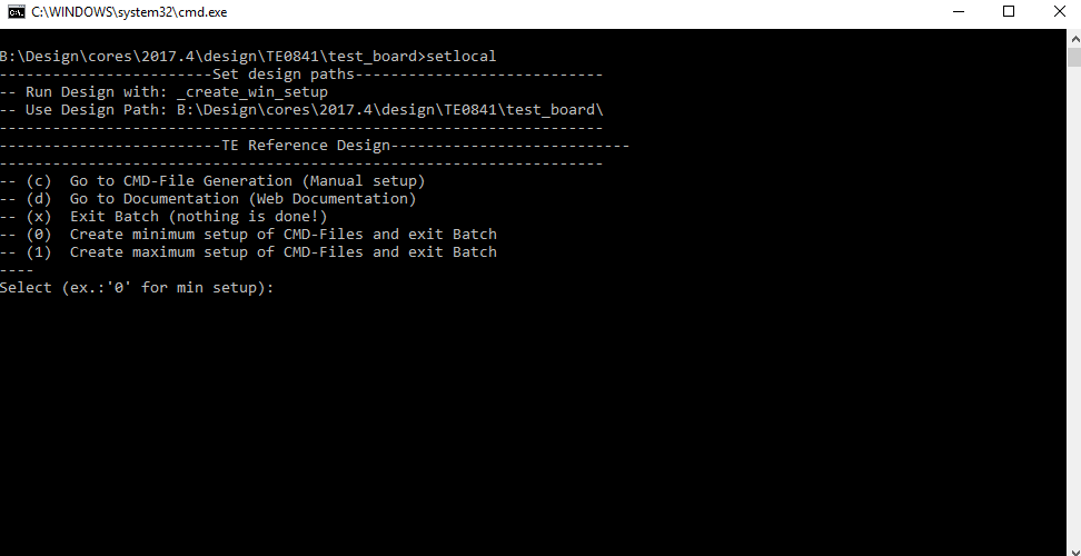
- Press 0 and enter for minimum setup
- (optional Win OS) Generate Virtual Drive or use short directory for the reference design (for example x:\<design name>)
- Create Project
- Select correct device and Xilinx install path on "design_basic_settings.cmd" and create Vivado project with "vivado_create_project_guimode.cmd"
Note: Select correct one, see TE Board Part Files
- Select correct device and Xilinx install path on "design_basic_settings.cmd" and create Vivado project with "vivado_create_project_guimode.cmd"
- Create HDF and export to prebuilt folder
- Run on Vivado TCL: TE::hw_build_design -export_prebuilt
Note: Script generate design and export files into \prebuilt\hardware\<short dir>. Use GUI is the same, except file export to prebuilt folder
- Run on Vivado TCL: TE::hw_build_design -export_prebuilt
- Generate MCS Firmware (optional):
- Create SDK Project with TE Scripts on Vivado TCL: TE::sw_run_sdk
- Create "SCU" application
Note: Select MCS Microblaze and SCU Application - Select Release Built
- Regenerate App
- (optional) Copy "\\workspace\sdk\scu\Release\scu.elf" into "\firmware\microblaze_mcs_0\"
- Regenerate Vivado Project or Update Bitfile only and "scu.elf"
- Copy MCS file with Bitfile into prebuilt folder
- Create SDK Project with TE Scripts on Vivado TCL: TE::sw_run_hsi
...
Xilinx documentation for programming and debugging: Vivado/SDK/SDSoC-Xilinx Software Programming and Debugging
QSPI
- Connect JTAG and power on PCB
- (if not done) Select correct device and Xilinx install path on "design_basic_settings.cmd" and create Vivado project with "vivado_create_project_guimode.cmd" or open with "vivado_open_project_guimode.cmd", if generated.
- Type on Vivado Console: TE::pr_program_flash_mcsfile -swapp
Note: Alternative use SDK or setup Flash on Vivado manually - Reboot (if not done automatically)
...
- Connect JTAG and power on PCB
- Open Vivado HW Manager
- Program FPGA with Bitfile from "prebuilt\hardware\<short dir>"Note SREC Bootloader try to find application on flash, this will stop, if Flash is empty.
Usage
- Prepare HW like described on section Programming 70156396
- Connect UART USB (most cases same as JTAG)
- Power on PCB
Note: FPGA Loads Bitfile from Flash,MCS Firmware configure SI5338 and starts MicroBlaze, MicroBlaze SREC Bootloader loads Hello TE0781 from Flash into RAM and starts application. Example will be run on UART console.IBERT.
Do not reboot, if Bitfile programming over JTAG is used as programming method.
UART
Open Serial Console (e.g. putty)
- Speed: 9600
- COM Port: Win OS, see device manager, Linux OS see dmesg |grep tty (UART is *USB1)
...
- On TE0841 SI5338 has default configuration and reprogramming of SI5338 is optional
- LED:
- D1 (green) OFF→ MCS SI configuration finished (System Reset is off)
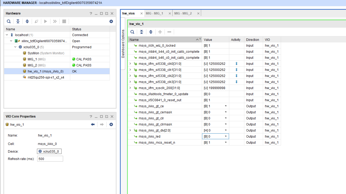
Vivado HW Manager:
- Open Vivado HW-Manager and add VIO signal to dashboard (*.ltx located on prebuilt folder).
- Set radix from VIO signals (fm_si...) to unsigned integer.
Note: Frequency Counter is inaccurate and displayed unit is Hz - SI will be configured with MCS firmware, default all off on PCB REV01
- LED control via VIO
- MGT CLK Freq can be changed over BUFG_GT control signals divider
- MCS Reset possible via VIO
- Set radix from VIO signals (fm_si...) to unsigned integer.
System Design - Vivado
| HTML |
|---|
<!--
Description of Block Design, Constrains...
BD Pictures from Export...
--> |
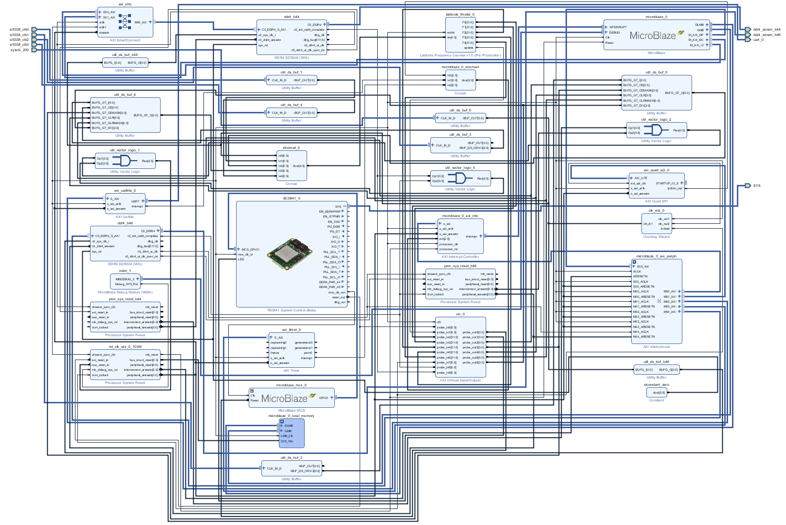
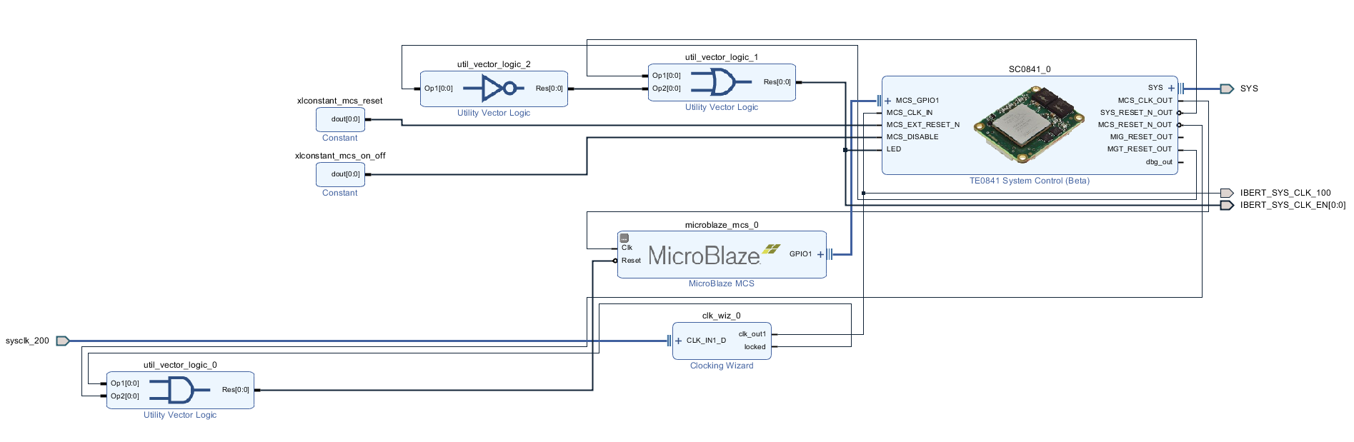
Block Design
Constrains
Basic module constrains
- Manager
- "Refresh device" is needed after Bitfile programming, because MCS reconfigure SI5338 and enables IBERT a little bit later.
- loopback depends on TEB0841 Revision an connection
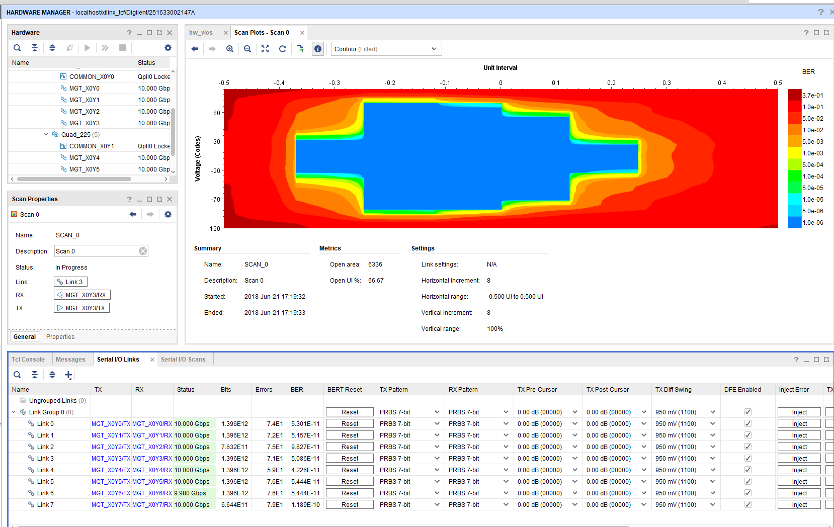
| IBERT | Component Name | Net Name | TEB0841 |
|---|---|---|---|
| X0Y0 | 224-0 | MGT4 | loop back RX/TX |
| X0Y1 | 224-1 | MGT5 | loop back RX/TX |
| X0Y2 | 224-2 | MGT6 | loopback over SD Pin header possible with lower Linerate otherwise use internal loopback |
| X0Y3 | 224-3 | MGT7 | loop back RX/TX. Note: N.C. on TEB0841-01, use internal loopback |
| X0Y4 | 225-0 | MGT0 | loop back RX/TX |
| X0Y5 | 225-1 | MGT1 | loop back RX/TX |
| X0Y6 | 225-2 | MGT2 | loop back RX/TX |
| X0Y7 | 225-3 | MGT3 | loopback over sfp possible |
System Design - Vivado
| HTML |
|---|
<!--
Description of Block Design, Constrains...
BD Pictures from Export...
--> |
Block Design
HDL
- IBERT_top.v
- ibert xci IPs
Constrains
Basic module constrains
| Code Block | ||||
|---|---|---|---|---|
| ||||
set_property BITSTREAM.GENERAL.COMPRESS TRUE | ||||
| Code Block | ||||
| ||||
set_property BITSTREAM.GENERAL.COMPRESS TRUE [current_design] set_property BITSTREAM.CONFIG.CONFIGRATE 69 [current_design] set_property CFGBVS GND [current_design] set_property CONFIG_VOLTAGE 1.8 [current_design] set_property CONFIG_MODE SPIx4 [current_design] set_property BITSTREAM.CONFIG.SPI_32BIT_ADDR YES [current_design] set_property BITSTREAM.CONFIG.SPI_BUSWIDTH 4 [current_design] set_property BITSTREAM.CONFIG.M1PINCONFIGRATE PULLNONE69 [current_design] set_property BITSTREAM.CONFIG.M2PIN PULLNONECFGBVS GND [current_design] set_property BITSTREAM.CONFIG_VOLTAGE 1.M0PIN8 PULLNONE [current_design] set_property BITSTREAM.CONFIG.USR_ACCESSMODE TIMESTAMPSPIx4 [current_design] |
Design specific constrain
| Code Block | ||||||
|---|---|---|---|---|---|---|
| ||||||
set_property CLOCK_DEDICATED_ROUTE BACKBONE [get_pins -hier -filter {NAME =~ */u_ddr4_infrastructure/gen_mmcme*.u_mmcme_adv_inst/CLKIN1}] create_clock -name ddr4_0_clk -period 4.95 [get_pins */ddr4_0/*/u_ddr4_infrastructure/gen_mmcme*.u_mmcme_adv_inst/CLKIN1] create_clock -name ddr4_1_clk -period 4.95 [get_pins */ddr4_1/*/u_ddr4_infrastructure/gen_mmcme*.u_mmcme_adv_inst/CLKIN1] set_property BITSTREAM.CONFIG.UNUSEDPIN PULLUP [current_design |
| Code Block | ||||||
|---|---|---|---|---|---|---|
| ||||||
# You must provide all the delay numbers
# CCLK delay is 0.1, 6.7 ns min/max for ultra-scale devices; refer Data sheet
# Consider the max delay for worst case analysis
set cclk_delay 6.7
create_generated_clock -name clk_sck -source [get_pins -hierarchical *axi_quad_spi_0/ext_spi_clk] -edges {3 5 7} -edge_shift [list $cclk_delay $cclk_delay $cclk_delay] [get_pins -hierarchical *USRCCLKO]
set_multicycle_path -setup -from clk_sck -to [get_clocks -of_objects [get_pins -hierarchical */ext_spi_clk]] 2
set_multicycle_path -hold -end -from clk_sck -to [get_clocks -of_objects [get_pins -hierarchical */ext_spi_clk]] 1
set_multicycle_path -setup -start -from [get_clocks -of_objects [get_pins -hierarchical */ext_spi_clk]] -to clk_sck 2
set_multicycle_path -hold -from [get_clocks -of_objects [get_pins -hierarchical */ext_spi_clk]] -to clk_sck 1
# Max delay constraints are used to instruct the tool to place IP near to STARTUPE3 primitive.
# If needed adjust the delays appropriately
set_max_delay -datapath_only -from [get_pins -hier {*STARTUP*_inst/DI[*]}] 1.000
set_max_delay -datapath_only -from [get_clocks clk_out2_msys_clk_wiz_0_0] -to [get_pins -hier *STARTUP*_inst/USRCCLKO] 1.000
#set_max_delay -datapath_only -from [get_clocks clk_out2_msys_clk_wiz_0_0] -to [get_pins -hier *STARTUP*_inst/DO[*] {*STARTUP*_inst/DTS[*]}] 1.000
set_max_delay -datapath_only -from [get_clocks clk_out2_msys_clk_wiz_0_0] -to [get_pins -hier *STARTUP*_inst/DO[*]] 1.000
set_max_delay -datapath_only -from [get_clocks clk_out2_msys_clk_wiz_0_0] -to [get_pins -hier *STARTUP*_inst/DTS[*]] 1.000
|
BITSTREAM.CONFIG.SPI_32BIT_ADDR YES [current_design]
set_property BITSTREAM.CONFIG.SPI_BUSWIDTH 4 [current_design]
set_property BITSTREAM.CONFIG.M1PIN PULLNONE [current_design]
set_property BITSTREAM.CONFIG.M2PIN PULLNONE [current_design]
set_property BITSTREAM.CONFIG.M0PIN PULLNONE [current_design]

set_property BITSTREAM.CONFIG.USR_ACCESS TIMESTAMP [current_design] |
Design specific constrain
| Code Block | ||||||
|---|---|---|---|---|---|---|
| ||||||
# file: ibert_ultrascale_gth_0.xdc
####################################################################################
##   ____  ____
##  /   /\/   /
## /___/  \  /    Vendor: Xilinx
## \   \   \/     Version : 2012.3
##  \   \         Application : IBERT Ultrascale
##  /   /         Filename : example_ibert_ultrascale_gth_0.xdc
## /___/   /\
## \   \  /  \
##  \___\/\___\
##
##
##
## Generated by Xilinx IBERT 7Series
##**************************************************************************
##
## Icon Constraints
##
create_clock -name D_CLK -period 10.0 [get_ports gth_sysclkp_i]
set_clock_groups -group [get_clocks D_CLK -include_generated_clocks] -asynchronous
set_property C_CLK_INPUT_FREQ_HZ 100000000 [get_debug_cores dbg_hub]
set_property C_ENABLE_CLK_DIVIDER true [get_debug_cores dbg_hub]

##gth_refclk lock constraints
##
set_property PACKAGE_PIN AD6 [get_ports gth_refclk0p_i[0]]
set_property PACKAGE_PIN AD5 [get_ports gth_refclk0n_i[0]]
set_property PACKAGE_PIN AB6 [get_ports gth_refclk1p_i[0]]
set_property PACKAGE_PIN AB5 [get_ports gth_refclk1n_i[0]]
##
## Refclk constraints
##
create_clock -name gth_refclk0_0 -period 8.0 [get_ports gth_refclk0p_i[0]]
create_clock -name gth_refclk1_0 -period 8.0 [get_ports gth_refclk1p_i[0]]
set_clock_groups -group [get_clocks gth_refclk0_0 -include_generated_clocks] -asynchronous
set_clock_groups -group [get_clocks gth_refclk1_0 -include_generated_clocks] -asynchronous
##
## System clock pin locs and timing constraints
##
#set_property PACKAGE_PIN R25 [get_ports gth_sysclkp_i]
#set_property IOSTANDARD LVDS [get_ports gth_sysclkp_i] | ||||||
| Code Block | ||||||
| ||||||
set_false_path -from [get_clocks {msys_i/util_ds_buf_5/U0/BUFG_GT_O[0]}] -to [get_clocks -of_objects [get_pins msys_i/clk_wiz_0/inst/mmcme3_adv_inst/CLKOUT0]]
set_false_path -from [get_clocks {msys_i/util_ds_buf_6/U0/BUFG_GT_O[0]}] -to [get_clocks -of_objects [get_pins msys_i/clk_wiz_0/inst/mmcme3_adv_inst/CLKOUT0]]
set_false_path -from [get_clocks -of_objects [get_pins msys_i/clk_wiz_0/inst/mmcme3_adv_inst/CLKOUT0]] -to [get_clocks {msys_i/util_ds_buf_6/U0/BUFG_GT_O[0]}]
set_false_path -from [get_clocks -of_objects [get_pins msys_i/clk_wiz_0/inst/mmcme3_adv_inst/CLKOUT0]] -to [get_clocks {msys_i/util_ds_buf_5/U0/BUFG_GT_O[0]}]

set_false_path -from [get_clocks -of_objects [get_pins msys_i/clk_wiz_0/inst/mmcme3_adv_inst/CLKOUT0]] -to [get_clocks {msys_i/util_ds_buf_1/U0/IBUF_OUT[0]}]
set_false_path -from [get_clocks -of_objects [get_pins msys_i/clk_wiz_0/inst/mmcme3_adv_inst/CLKOUT0]] -to [get_clocks {msys_i/util_ds_buf_4/U0/IBUF_OUT[0]}]
set_false_path -from [get_clocks {msys_i/util_ds_buf_1/U0/IBUF_OUT[0]}] -to [get_clocks -of_objects [get_pins msys_i/clk_wiz_0/inst/mmcme3_adv_inst/CLKOUT0]]
set_false_path -from [get_clocks {msys_i/util_ds_buf_4/U0/IBUF_OUT[0]}] -to [get_clocks -of_objects [get_pins msys_i/clk_wiz_0/inst/mmcme3_adv_inst/CLKOUT0]]
|
Software Design - SDK/HSI
...
MCS Firmware to configure SI5338 and Reset System.
Template location: \sw_lib\sw_apps\scu
Hello TE0841
Xilinx Hello World example as endless loop
Template location: \sw_lib\sw_apps\hello_te0841
SREC SPI Bootloader
Modified Xilinx SREC Bootloader. Changes: Correct flash typ and SRec Start address, some additional console outputs, see source code
Template location: \sw_lib\sw_apps\srec_spi_bootloader \sw_lib\sw_services\xilisf_v5_9scu
Additional Software
| HTML |
|---|
<!-- Add Description for other Software, for example SI CLK Builder ... --> |
...
| Date | Document Revision | Authors | Description | ||||||||||||||||||||||||
|---|---|---|---|---|---|---|---|---|---|---|---|---|---|---|---|---|---|---|---|---|---|---|---|---|---|---|---|
|
|
|
| ||||||||||||||||||||||||
| v.5 | John Hartfiel |
| |||||||||||||||||||||||||
| v.4 | John Hartfiel |
| |||||||||||||||||||||||||
| 2018-04-16 | v.1 |
|
| ||||||||||||||||||||||||
| All |
|
...
Overview
Content Tools