Page History
| Page properties | ||||||||||||||||||||||||||||||||||||||||
|---|---|---|---|---|---|---|---|---|---|---|---|---|---|---|---|---|---|---|---|---|---|---|---|---|---|---|---|---|---|---|---|---|---|---|---|---|---|---|---|---|
| ||||||||||||||||||||||||||||||||||||||||
Design Name is always "TE Series Name" + Design name, for example "TE0720 Test Board"
|
| Custom_table_size_100 |
|---|
| Page properties | ||||||||||||||||||||||||||||||||||||||||
|---|---|---|---|---|---|---|---|---|---|---|---|---|---|---|---|---|---|---|---|---|---|---|---|---|---|---|---|---|---|---|---|---|---|---|---|---|---|---|---|---|
| ||||||||||||||||||||||||||||||||||||||||
Important General Note:
|
Overview
| Scroll Ignore | ||||||||||||||
|---|---|---|---|---|---|---|---|---|---|---|---|---|---|---|
| ||||||||||||||
| Page properties | ||||
|---|---|---|---|---|
| ||||
Notes :
|
Refer to http://trenz.org/te0712-info for the current online version of this manual and other available documentation.
For directly getting started with the prebuilt files jump to the section Launch.
Key Features
| Page properties | ||||
|---|---|---|---|---|
| ||||
Notes :
|
| Excerpt |
|---|
|
Revision History
| Page properties | ||||
|---|---|---|---|---|
| ||||
Notes :
|
| Scroll Title | ||||||||||||||||||||||||||||||||||||||||||||||||||||||||||||||||||||||||||||||||||||||||||||||||||||||||||||||||||||||
|---|---|---|---|---|---|---|---|---|---|---|---|---|---|---|---|---|---|---|---|---|---|---|---|---|---|---|---|---|---|---|---|---|---|---|---|---|---|---|---|---|---|---|---|---|---|---|---|---|---|---|---|---|---|---|---|---|---|---|---|---|---|---|---|---|---|---|---|---|---|---|---|---|---|---|---|---|---|---|---|---|---|---|---|---|---|---|---|---|---|---|---|---|---|---|---|---|---|---|---|---|---|---|---|---|---|---|---|---|---|---|---|---|---|---|---|---|---|---|
| ||||||||||||||||||||||||||||||||||||||||||||||||||||||||||||||||||||||||||||||||||||||||||||||||||||||||||||||||||||||
|
Release Notes and Known Issues
| Page properties | ||||
|---|---|---|---|---|
| ||||
Notes :
|
| Scroll Title | ||||||||||||||||||||||||||||||||||
|---|---|---|---|---|---|---|---|---|---|---|---|---|---|---|---|---|---|---|---|---|---|---|---|---|---|---|---|---|---|---|---|---|---|---|
| ||||||||||||||||||||||||||||||||||
|
Requirements
Software
| Page properties | ||||
|---|---|---|---|---|
| ||||
Notes :
|
| Scroll Title | ||||||||||||||||||||||||||
|---|---|---|---|---|---|---|---|---|---|---|---|---|---|---|---|---|---|---|---|---|---|---|---|---|---|---|
| ||||||||||||||||||||||||||
|
Hardware
| Page properties | ||||
|---|---|---|---|---|
| ||||
Notes :
|
Complete List is available on "<project folder>\board_files\*_board_files.csv"
Design supports following modules:
| Scroll Title | ||||||||||||||||||||||||||||||||||||||||||||||||||||||||||||||||||||||||||||||||||||||||||||||||||||||||||||||||||||||||||||||||||||||||||||||||||||||||||||||||||||||||||||||||||||||||||||||||||||||||||||||||||||||||||||||||||||||||||||||||||||||||||||||||||||||||||||||||||||||||||||||||||||||||||||||||||||||||||||||||||||||||||||||||||||||||||||||||||||||||||||||||||||||||||||||||||||||||||||||||||||||||||||||||||||||||||||||||||||||||||||||||||||||||||||||||||||||||||||||||||||||||||||||||||||||||||||||||||||||||||
|---|---|---|---|---|---|---|---|---|---|---|---|---|---|---|---|---|---|---|---|---|---|---|---|---|---|---|---|---|---|---|---|---|---|---|---|---|---|---|---|---|---|---|---|---|---|---|---|---|---|---|---|---|---|---|---|---|---|---|---|---|---|---|---|---|---|---|---|---|---|---|---|---|---|---|---|---|---|---|---|---|---|---|---|---|---|---|---|---|---|---|---|---|---|---|---|---|---|---|---|---|---|---|---|---|---|---|---|---|---|---|---|---|---|---|---|---|---|---|---|---|---|---|---|---|---|---|---|---|---|---|---|---|---|---|---|---|---|---|---|---|---|---|---|---|---|---|---|---|---|---|---|---|---|---|---|---|---|---|---|---|---|---|---|---|---|---|---|---|---|---|---|---|---|---|---|---|---|---|---|---|---|---|---|---|---|---|---|---|---|---|---|---|---|---|---|---|---|---|---|---|---|---|---|---|---|---|---|---|---|---|---|---|---|---|---|---|---|---|---|---|---|---|---|---|---|---|---|---|---|---|---|---|---|---|---|---|---|---|---|---|---|---|---|---|---|---|---|---|---|---|---|---|---|---|---|---|---|---|---|---|---|---|---|---|---|---|---|---|---|---|---|---|---|---|---|---|---|---|---|---|---|---|---|---|---|---|---|---|---|---|---|---|---|---|---|---|---|---|---|---|---|---|---|---|---|---|---|---|---|---|---|---|---|---|---|---|---|---|---|---|---|---|---|---|---|---|---|---|---|---|---|---|---|---|---|---|---|---|---|---|---|---|---|---|---|---|---|---|---|---|---|---|---|---|---|---|---|---|---|---|---|---|---|---|---|---|---|---|---|---|---|---|---|---|---|---|---|---|---|---|---|---|---|---|---|---|---|---|---|---|---|---|---|---|---|---|---|---|---|---|---|---|---|---|---|---|---|---|---|---|---|---|---|---|---|---|---|---|---|---|---|---|---|---|---|---|---|---|---|---|---|---|---|---|---|---|---|---|---|---|---|---|---|---|---|---|---|---|---|---|---|---|---|---|---|---|---|---|---|---|---|---|---|---|---|---|---|---|---|---|---|---|---|---|---|---|---|---|---|---|---|---|---|---|---|---|---|---|---|---|---|---|---|---|---|---|---|---|---|---|---|---|---|---|---|---|---|---|---|---|---|---|---|---|---|---|---|---|---|---|---|---|
| ||||||||||||||||||||||||||||||||||||||||||||||||||||||||||||||||||||||||||||||||||||||||||||||||||||||||||||||||||||||||||||||||||||||||||||||||||||||||||||||||||||||||||||||||||||||||||||||||||||||||||||||||||||||||||||||||||||||||||||||||||||||||||||||||||||||||||||||||||||||||||||||||||||||||||||||||||||||||||||||||||||||||||||||||||||||||||||||||||||||||||||||||||||||||||||||||||||||||||||||||||||||||||||||||||||||||||||||||||||||||||||||||||||||||||||||||||||||||||||||||||||||||||||||||||||||||||||||||||||||||||
*used as reference |
Design supports following carriers:
| Scroll Title | ||||||||||||||||||||||||||||||
|---|---|---|---|---|---|---|---|---|---|---|---|---|---|---|---|---|---|---|---|---|---|---|---|---|---|---|---|---|---|---|
| ||||||||||||||||||||||||||||||
*used as reference |
Additional HW Requirements:
| Scroll Title | ||||||||||||||||||||||||
|---|---|---|---|---|---|---|---|---|---|---|---|---|---|---|---|---|---|---|---|---|---|---|---|---|
| ||||||||||||||||||||||||
|
Content
| Page properties | ||||
|---|---|---|---|---|
| ||||
Notes :
|
For general structure and usage of the reference design, see Project Delivery - AMD devices
Design Sources
| Scroll Title | ||||||||||||||||||||||||||
|---|---|---|---|---|---|---|---|---|---|---|---|---|---|---|---|---|---|---|---|---|---|---|---|---|---|---|
| ||||||||||||||||||||||||||
|
Additional Sources
| Scroll Title | ||||||||||||||||||||||||
|---|---|---|---|---|---|---|---|---|---|---|---|---|---|---|---|---|---|---|---|---|---|---|---|---|
| ||||||||||||||||||||||||
|
Prebuilt
| Page properties | ||||||||||||||||||||||||||||||||||||||||||||||||||||||||||||||||||||||||
|---|---|---|---|---|---|---|---|---|---|---|---|---|---|---|---|---|---|---|---|---|---|---|---|---|---|---|---|---|---|---|---|---|---|---|---|---|---|---|---|---|---|---|---|---|---|---|---|---|---|---|---|---|---|---|---|---|---|---|---|---|---|---|---|---|---|---|---|---|---|---|---|---|
| ||||||||||||||||||||||||||||||||||||||||||||||||||||||||||||||||||||||||
Notes :
|
| Scroll Title | |||||||||||||||||||||||||||||||||||||||||||||||||||
|---|---|---|---|---|---|---|---|---|---|---|---|---|---|---|---|---|---|---|---|---|---|---|---|---|---|---|---|---|---|---|---|---|---|---|---|---|---|---|---|---|---|---|---|---|---|---|---|---|---|---|---|
| |||||||||||||||||||||||||||||||||||||||||||||||||||
|
Download
Reference Design is only usable with the specified Vivado/Vitis/PetaLinux version. Do never use different Versions of AMD(Xilinx) Software for the same Project.
| Page properties | ||||
|---|---|---|---|---|
| ||||
|
Reference Design is available on:
Design Flow
| Scroll Ignore | ||||||||||||||
|---|---|---|---|---|---|---|---|---|---|---|---|---|---|---|
| ||||||||||||||
| Page properties | ||||
|---|---|---|---|---|
| ||||
Notes :
|
| Note |
|---|
Reference Design is available with and without prebuilt files. It's recommended to use TE prebuilt files for first launch. |
See also: AMD Development Tools#XilinxSoftware-BasicUserGuides
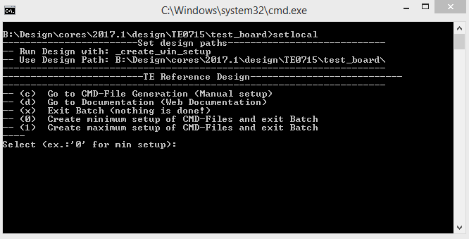
The Trenz Electronic FPGA Reference Designs are TCL-script based project. Command files for execution will be generated with "_create_win_setup.cmd" on Windows OS and "_create_linux_setup.sh" on Linux OS.
TE Scripts are only needed to generate the vivado project, all other additional steps are optional and can also executed by Vivado/Vitis GUI. For currently Scripts limitations on Win and Linux OS see: Project Delivery Currently limitations of functionality
| Note |
|---|
Caution! Win OS has a 260 character limit for path lengths which can affect the Vivado tools. To avoid this issue, use Virtual Drive or the shortest possible names and directory locations for the reference design (for example "x:\<project folder>") |
Run _create_win_setup.cmd/_create_linux_setup.sh and follow instructions on shell:
Code Block language bash theme Midnight title _create_win_setup.cmd/_create_linux_setup.sh ------------------------Set design paths---------------------------- -- Run Design with: _create_win_setup -- Use Design Path: <absolute project path> -------------------------------------------------------------------- -------------------------TE Reference Design--------------------------- -------------------------------------------------------------------- -- (0) Module selection guide, project creation...prebuilt export... -- (1) Create minimum setup of CMD-Files and exit Batch -- (2) Create maximum setup of CMD-Files and exit Batch -- (3) (internal only) Dev -- (4) (internal only) Prod -- (c) Go to CMD-File Generation (Manual setup) -- (d) Go to Documentation (Web Documentation) -- (g) Install Board Files from Xilinx Board Store (beta) -- (a) Start design with unsupported Vivado Version (beta) -- (x) Exit Batch (nothing is done!) ---- Select (ex.:'0' for module selection guide):Press 0 and enter to start "Module Selection Guide"
- (optional Win OS) Generate Virtual Drive or use short directory for the reference design (for example x:\<design name>)
- Createproject and follow instructions of the product selection guide, settings file will be configured automatically during this process.
optional for manual changes: Select correct device and AMD(Xilinx) install path on "design_basic_settings.cmd" and create Vivado project with "vivado_create_project_guimode.cmd"
Note Note: Select correct one, see also Vivado Board Part Flow
Create hardware description file (.xsa file) for PetaLinux project and export to prebuilt folder
Code Block language py theme Midnight title run on Vivado TCL (Script generates design and export files into "<project folder>\prebuilt\hardware\<short name>") TE::hw_build_design -export_prebuiltInfo Using Vivado GUI is the same, except file export to prebuilt folder.
- Create and configure your PetaLinux project with exported .xsa-file, see PetaLinux KICKstart
- use TE Template from "<project folder>\os\petalinux"
use exported .xsa file from "<project folder>\prebuilt\hardware\<short name>" . Note: HW Export from Vivado GUI creates another path as default workspace.
The petalinux build images are located in the "<plnx-proj-root>/images/linux" directory
Info Important Note: Select correct Flash partition offset on petalinux-config: Subsystem Auto HW Settings → Flash Settings, FPGA+Boot+bootenv=0xA00000 (increase automatically generate Boot partition), increase image size to A:, see Config
- Configure the boot.scr file as needed, see Distro Boot with Boot.scr. Kernel flash address and kernel size are set here.
- Copy PetaLinux build image files to prebuilt folder
copy u-boot.elf, image.ub and boot.scr from "<plnx-proj-root>/images/linux" to prebuilt folder
Info "<project folder>\prebuilt\os\petalinux\<ddr size>" or "<project folder>\prebuilt\os\petalinux\<short name>"
Page properties hidden true id Comments This step depends on Xilinx Device/Hardware
for Zynq-7000 series
- copy u-boot.elf, image.ub and boot.scr from "<plnx-proj-root>/images/linux" to prebuilt folder
for ZynqMP
- copy u-boot.elf, bl31.elf, image.ub and boot.scr from "<plnx-proj-root>/images/linux" to prebuilt folder
for ...
- ...
Generate Programming Files with Vitis
Code Block language py theme Midnight title run on Vivado TCL (Script generates applications and bootable files, which are defined in "test_board\sw_lib\apps_list.csv") TE::sw_run_vitis -all TE::sw_run_vitis (optional; Start Vitis from Vivado GUI or start with TE Scripts on Vivado TCL)Note TCL scripts generate also platform project, this must be done manually in case GUI is used. See Vitis
- (Optional) BlockRam Firmware Update
Copy "<project folder>\prebuilt\software\<short name>\spi_bootloader.elf" into "<project folder>\firmware\microblaze_0\"
Copy "<project folder>\workspace\sdk\scu_te0712\Release\scu_te0712.elf" into "\firmware\microblaze_mcs_0\"
Regenerate Vivado Project or Update Bitfile only with "spi_bootloader.elf" and "scu_te0712.elf"
Code Block language bash theme Midnight TE::hw_build_design -export_prebuilt TE::sw_run_vitis -all
Launch
| Scroll Ignore | ||||||||||||||
|---|---|---|---|---|---|---|---|---|---|---|---|---|---|---|
| ||||||||||||||
Programming
| Page properties | ||||
|---|---|---|---|---|
| ||||
Note:
|
| Note |
|---|
Check Module and Carrier TRMs for proper HW configuration before you try any design. Reference Design is also available with prebuilt files. It's recommended to use TE prebuilt files for first launch. |
AMD(Xilinx) documentation for programming and debugging: Vivado/Vitis/SDSoC-Xilinx Software Programming and Debugging
Get prebuilt boot binaries
- Run _create_win_setup.cmd/_create_linux_setup.sh and follow instructions on shell
- Press 0 and enter to start "Module Selection Guide"
- Select assembly version
- Validate selection
Select create and open delivery binary folder
Info Note: Folder "<project folder>\_binaries_<Article Name>" with subfolder "boot_<app name>" for different applications will be generated
QSPI-Boot mode
Option for u-boot.mcs on QSPI Flash.
(u-boot.mcs contains all files necessary to boot up linux)
Connect the USB cable(JTAG) and power supply on carrier with module
Open Vivado Project with "vivado_open_existing_project_guimode.cmd" or if not created, create with "vivado_create_project_guimode.cmd".
Enter the following TCL-Command into the TCL-Console inside Vivado to program the QSPI Flash.Code Block language py theme Midnight title run on Vivado TCL (Script programs u-boot.mcs onto QSPI flash) TE::pr_program_flash -swapp u-bootReboot (if not done automatically)
SD-Boot mode
Not used on this Example.
JTAG
Not used on this Example.
Usage
Prepare HW like described on section Programming
Connect UART USB (most cases same as JTAG)
Select QSPI as Boot Mode
Info Note: See TRM of the Carrier, which is used.
Power On PCB and push the reset button if present on carrier.
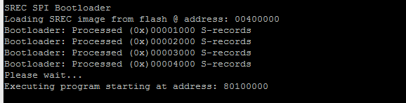
Expand title boot process 1. FPGA Loads Bitfile from Flash,
2. MCS Firmware configure SI5338 (per default off with REV03) and starts Microblaze,
3. SPI Bootloader from Bitfile Firmware loads U-Boot into DDR (This takes a while),
4. U-boot loads Linux from QSPI Flash into DDR
Linux
Open Serial Console (e.g. putty)
Speed: 9600
COM Port
Info Win OS, see device manager, Linux OS see dmesg |grep tty (UART is *USB1)
Boot process takes a while, please wait...
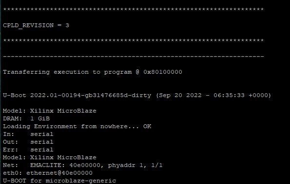
Linux Console:
Code Block language bash theme Midnight petalinux login: petalinux -> assign new passwordInfo Note: Wait until Linux boot finished.
Linux boot process is slower on Microblaze.
You can use Linux shell now.
Code Block language bash theme Midnight udhcpc (ETH0 check)
Vivado HW Manager
| Page properties | ||||
|---|---|---|---|---|
| ||||
Note:
|
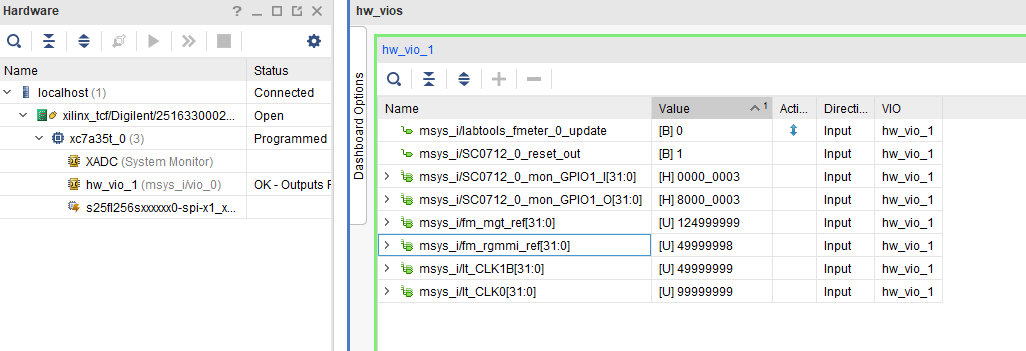
Open Vivado HW-Manager and add VIO signal to dashboard (*.ltx located on prebuilt folder).
Set radix from VIO signals (MGT REF, MIG_OUT, CLK1B, CLK0) to unsigned integer.
Note: Frequency Counter is inaccurate and displayed unit is Hz
Monitoring:
MGT REF~125MHz, MIG_50MHZ~50MHz., CLK1B ~50MHz, CLK0~100MHz
System reset from MCS and GIO outputs
- 1. → Si5338 PLL was programmed 0 = NO | 1 = YES
- 2. → Error occurred during PLL programming 0 = NO | 1 = YES
- 3. → Module Revision ( Can be set in the Blockdiagram → SC0712 IP)
draw.io Diagram border true diagramName HWManager_TE0712 simpleViewer false width 900 links auto tbstyle top diagramDisplayName lbox true diagramWidth 1599 revision 4
System Design - Vivado
| Scroll Ignore | ||||||||||||||
|---|---|---|---|---|---|---|---|---|---|---|---|---|---|---|
| ||||||||||||||
| Page properties | ||||
|---|---|---|---|---|
| ||||
Note:
|
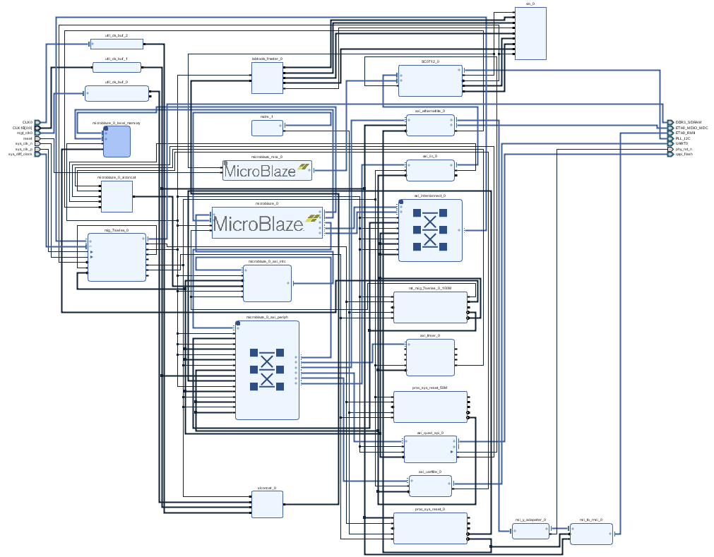
Block Design
| draw.io Diagram | ||||||||||||||||||||||
|---|---|---|---|---|---|---|---|---|---|---|---|---|---|---|---|---|---|---|---|---|---|---|
|
Constraints
Basic module constraints
| Code Block | ||||
|---|---|---|---|---|
| ||||
set_property BITSTREAM.GENERAL.COMPRESS TRUE [current_design]
set_property BITSTREAM.CONFIG.CONFIGRATE 66 [current_design]
set_property CONFIG_VOLTAGE 3.3 [current_design]
set_property CFGBVS VCCO [current_design]
set_property CONFIG_MODE SPIx4 [current_design]
set_property BITSTREAM.CONFIG.SPI_32BIT_ADDR YES [current_design]
set_property BITSTREAM.CONFIG.SPI_BUSWIDTH 4 [current_design]
set_property BITSTREAM.CONFIG.M1PIN PULLNONE [current_design]
set_property BITSTREAM.CONFIG.M2PIN PULLNONE [current_design]
set_property BITSTREAM.CONFIG.M0PIN PULLNONE [current_design]

set_property BITSTREAM.CONFIG.USR_ACCESS TIMESTAMP [current_design] |
| Code Block | ||||
|---|---|---|---|---|
| ||||
set_property BITSTREAM.CONFIG.UNUSEDPIN PULLDOWN [current_design] |
Design specific constraints
| Code Block | ||||
|---|---|---|---|---|
| ||||
set_property PULLDOWN true [get_ports reset] |
| Code Block | ||||
|---|---|---|---|---|
| ||||
#I2C
#set_property PACKAGE_PIN W21 [get_ports PLL_I2C_scl_io]
#set_property IOSTANDARD LVCMOS33 [get_ports PLL_I2C_scl_io]
#set_property PACKAGE_PIN T20 [get_ports PLL_I2C_sda_io]
#set_property IOSTANDARD LVCMOS33 [get_ports PLL_I2C_sda_io]
set_property PACKAGE_PIN W21 [get_ports PLL_I2C_ext_scl_o]
set_property IOSTANDARD LVCMOS33 [get_ports PLL_I2C_ext_scl_o]
set_property PACKAGE_PIN T20 [get_ports PLL_I2C_ext_sda]
set_property IOSTANDARD LVCMOS33 [get_ports PLL_I2C_ext_sda]

#Reset
set_property PACKAGE_PIN T3 [get_ports reset]
set_property IOSTANDARD LVCMOS15 [get_ports reset]
#CLKS
set_property PACKAGE_PIN R4 [get_ports {CLK1B[0]}]
set_property IOSTANDARD LVCMOS15 [get_ports {CLK1B[0]}]
set_property PACKAGE_PIN K4 [get_ports {CLK0_clk_p[0]}]
set_property IOSTANDARD DIFF_SSTL15 [get_ports {CLK0_clk_p[0]}]

#ETH PHY
set_property PACKAGE_PIN N17 [get_ports phy_rst_n]
set_property IOSTANDARD LVCMOS33 [get_ports phy_rst_n]

#EEPROM onewire (MAC ADDRESS)
set_property IOSTANDARD LVCMOS33 [get_ports EEPROM_tri_io]
set_property PACKAGE_PIN V22 [get_ports EEPROM_tri_io]

#I2C connected to CPLD
set_property -dict {IOSTANDARD LVCMOS33 PACKAGE_PIN W22} [get_ports IIC_0_scl_io]
set_property -dict {IOSTANDARD LVCMOS33 PACKAGE_PIN U22} [get_ports IIC_0_sda_io] |
| Code Block | ||||
|---|---|---|---|---|
| ||||
create_clock -period 8.000 -name mgt_clk0_clk_p -waveform {0.000 4.000} [get_ports mgt_clk0_clk_p]


create_clock -period 10.000 -name {CLK0_clk_p[0]} -waveform {0.000 5.000} [get_ports {CLK0_clk_p[0]}]
create_clock -period 20.000 -name {CLK1B[0]} -waveform {0.000 10.000} [get_ports {CLK1B[0]}]
create_clock -period 15.152 -name CFGMCLK -waveform {0.000 7.576} [get_pins -hierarchical -filter {NAME =~*NO_DUAL_QUAD_MODE.QSPI_NORMAL/*STARTUP_7SERIES_GEN.STARTUP2_7SERIES_inst/CFGMCLK}]


set_false_path -from [get_clocks {CLK0_clk_p[0]}] -to [get_clocks clk_pll_i]
set_false_path -from [get_clocks mgt_clk0_clk_p] -to [get_clocks clk_pll_i]
set_false_path -from [get_pins {msys_i/SC0712_0/U0/rst_delay_i_reg[3]/C}] -to [get_pins -hierarchical -filter {NAME =~*u_msys_mig_7series_0_0_mig/u_ddr3_infrastructure/rstdiv0*/PRE}]
set_false_path -from [get_clocks -of_objects [get_pins msys_i/mig_7series_0/u_msys_mig_7series_0_0_mig/u_ddr3_infrastructure/gen_ui_extra_clocks.mmcm_i/CLKFBOUT]] -to [get_clocks mgt_clk0_clk_p]
set _xlnx_shared_i0 [get_pins {msys_i/vio_0/inst/PROBE_IN_INST/probe_in_reg_reg[*]/D}]
set_false_path -from [get_pins {msys_i/labtools_fmeter_0/U0/F_reg[*]/C}] -to $_xlnx_shared_i0
set_false_path -from [get_pins msys_i/labtools_fmeter_0/U0/COUNTER_REFCLK_inst/bl.DSP48E_2/CLK] -to $_xlnx_shared_i0
set_false_path -from [get_pins {msys_i/labtools_fmeter_0/U0/FMETER_gen[*].COUNTER_F_inst/bl.DSP48E_2/CLK}] -to [get_pins {msys_i/labtools_fmeter_0/U0/F_reg[*]/D}] |
Software Design - Vitis
| Scroll Ignore | ||||||||||||||
|---|---|---|---|---|---|---|---|---|---|---|---|---|---|---|
| ||||||||||||||
| Page properties | ||||
|---|---|---|---|---|
| ||||
Note:
|
For Vitis project creation, follow instructions from:
Application
| Page properties | ||||
|---|---|---|---|---|
| ||||
---------------------------------------------------------- FPGA Example scuMCS Firmware to configure SI5338 and Reset System. spi_bootloaderTE modified SPI Bootloader from Henrik Brix Andersen. Bootloader to load app or second bootloader from flash into DDR Descriptions:
xilisf_v5_11TE modified 2020.2 xilisf_v5_11
---------------------------------------------------------- Zynq Example: fsblTE modified 2020.2 FSBL General:
Module Specific:
fsbl_flashTE modified 2020.2 FSBL General:
ZynqMP Example: ---------------------------------------------------------- zynqmp_fsblTE modified 2020.2 FSBL General:
Module Specific:
zynqmp_fsbl_flashTE modified 2020.2 FSBL General:
zynqmp_pmufwXilinx default PMU firmware. ---------------------------------------------------------- General Example: hello_te0820Hello TE0820 is a Xilinx Hello World example as endless loop instead of one console output. u-bootU-Boot.elf is generated with PetaLinux. Vitis is used to generate Boot.bin. eepromeeprom is a petalinux application that executes on startup. It reads the unique 48-bit MAC from the onboard eeprom and uses it to set the system MAC address. |
Template location: "<project folder>\sw_lib\sw_apps\"
scu_te0712
MCS Firmware to configure SI5338 and Reset System.
spi_bootloader
TE modified SPI Bootloader from Henrik Brix Andersen.
Bootloader to load app or second bootloader from flash into DDR.
Here it loads the u-boot.elf from QSPI-Flash to RAM. Hence u-boot.srec becomes redundant.
Descriptions:
- Modified Files: bootloader.c
- Changes:
- Change the SPI defines in the header
- Add some reiteration in the frist spi read call
hello_te0712
Hello TE0712 is a AMD(Xilinx) Hello World example as endless loop instead of one console output.
u-boot
U-Boot.elf is generated with PetaLinux. Vitis is used to generate u-boot.srec(obsolete). Vivado to generate *.mcs
Software Design - PetaLinux
| Scroll Ignore | ||||||||||||||
|---|---|---|---|---|---|---|---|---|---|---|---|---|---|---|
| ||||||||||||||
| Page properties | ||||
|---|---|---|---|---|
| ||||
Note:
|
For PetaLinux installation and project creation, follow instructions from:
Config
Start with petalinux-config or petalinux-config --get-hw-description
(Tipp: Search for Settings with shortcut "Shift"+"/")
Changes:
SUBSYSTEM_FLASH_AXI_QUAD_SPI_0_BANKLESS_PART0_SIZE = 0x5E0000 (fpga)
SUBSYSTEM_FLASH_AXI_QUAD_SPI_0_BANKLESS_PART1_SIZE = 0x400000 (boot)
SUBSYSTEM_FLASH_AXI_QUAD_SPI_0_BANKLESS_PART2_SIZE = 0x20000 (bootenv)
SUBSYSTEM_FLASH_AXI_QUAD_SPI_0_BANKLESS_PART3_SIZE = 0xB00000 (kernel)
(with this kernel flash address is 0xA00000 (fpga+boot+bootenv) and Kernel size 0xB00000)
U-Boot
Start with petalinux-config -c u-boot
Changes:
CONFIG_ENV_IS_NOWHERE=y
# CONFIG_ENV_IS_IN_SPI_FLASH is not set
# CONFIG_PHY_ATHEROS is not set
# CONFIG_PHY_BROADCOM is not set
# CONFIG_PHY_DAVICOM is not set
# CONFIG_PHY_LXT is not set
# CONFIG_PHY_MICREL_KSZ90X1 is not set
# CONFIG_PHY_MICREL is not set
# CONFIG_PHY_NATSEMI is not set
# CONFIG_PHY_REALTEK is not set
CONFIG_RGMII=y
Content of platform-top.h located in <plnx-proj-root>\project-spec\meta-user\recipes-bsp\u-boot\files:
| Code Block | ||
|---|---|---|
| ||
#include <configs/microblaze-generic.h>
#include <configs/platform-auto.h>

#define CONFIG_SYS_BOOTM_LEN 0xF000000 |
Device Tree
Content of system-user.dtsi located in <petalinux project directory>\project-spec\meta-user\recipes-bsp\device-tree\files:
| Code Block | ||
|---|---|---|
| ||
/include/ "system-conf.dtsi"
/ {
};

/* QSPI PHY */

&axi_quad_spi_0 {
    #address-cells = <1>;
    #size-cells = <0>;
    flash0: flash@0 {
        compatible = "jedec,spi-nor";
        spi-tx-bus-width=<1>;
        spi-rx-bus-width=<4>;
        reg = <0x0>;
        #address-cells = <1>;
        #size-cells = <1>;
        spi-max-frequency = <25000000>;
    };
};


/* ETH PHY */
&axi_ethernetlite_0 {
    phy-handle = <&phy0>;
    mdio {
        #address-cells = <1>;
        #size-cells = <0>;
        phy0: phy@0 {
            device_type = "ethernet-phy";
            reg = <1>;
        };
    };
}; |
Kernel
Start with petalinux-config -c kernel
Changes:
No changes.
Rootfs
Start with petalinux-config -c rootfs
Changes:
# CONFIG_dropbear is not set
# CONFIG_dropbear-dev is not set
# CONFIG_dropbear-dbg is not set
# CONFIG_package-group-core-ssh-dropbear is not set
# CONFIG_packagegroup-core-ssh-dropbear-dev is not set
# CONFIG_packagegroup-core-ssh-dropbear-dbg is not set
# CONFIG_imagefeature-ssh-server-dropbear is not set
optional: to change the password settings at startup look at Adding extra users to the petalinux system.
"Dropbear" is part of the "petalinux-image-minimal" configuration, so changes in the petalinux rootfs will not be applied. To remove "dropbear" anyway, enter the following line in petalinuxbsp.conf in ..\petalinux\project-spec\meta-user\conf:
| Code Block | ||||
|---|---|---|---|---|
| ||||
PACKAGE_EXCLUDE += " dropbear dropbear-openssh-sftp-server dropbear-dev dropbear-dbg dropbear-openssh-sftp-server packagegroup-core-ssh-dropbear packagegroup-core-ssh-dropbear-dbg packagegroup-core-ssh-dropbear-dev" |
Applications
No additional application.
Additional Software
| Page properties | ||||
|---|---|---|---|---|
| ||||
Note: |
SI5338
File location "<project folder>\misc\Si5338\Si5338-*.slabtimeproj"
General documentation how you work with this project will be available on Si5338
| Scroll Ignore | ||||||||||||||
|---|---|---|---|---|---|---|---|---|---|---|---|---|---|---|
| ||||||||||||||
Appx. A: Change History and Legal Notices
Document Change History
To get content of older revision got to "Change History" of this page and select older document revision number.
| Page properties | ||||
|---|---|---|---|---|
| ||||
|
| Scroll Title | ||||||||||||||||||||||||||||||||||||||||||||||||||||||||||||||||||||||||||||||||||||||||||||||||||||||||||||||||||||||||
|---|---|---|---|---|---|---|---|---|---|---|---|---|---|---|---|---|---|---|---|---|---|---|---|---|---|---|---|---|---|---|---|---|---|---|---|---|---|---|---|---|---|---|---|---|---|---|---|---|---|---|---|---|---|---|---|---|---|---|---|---|---|---|---|---|---|---|---|---|---|---|---|---|---|---|---|---|---|---|---|---|---|---|---|---|---|---|---|---|---|---|---|---|---|---|---|---|---|---|---|---|---|---|---|---|---|---|---|---|---|---|---|---|---|---|---|---|---|---|---|---|
| ||||||||||||||||||||||||||||||||||||||||||||||||||||||||||||||||||||||||||||||||||||||||||||||||||||||||||||||||||||||||
|
| HTML |
|---|
<!--
Template Revision 1.0
Basic Notes
 - export PDF to download, if vivado revision is changed!
 - Template is for different design and SDSoC and examples, remove unused or wrong description!
--> |
| Scroll Only (inline) |
|---|
Online version of this manual and other related documents can be found at https://wiki.trenz-electronic.de/display/PD/Trenz+Electronic+Documentation |
| Scroll pdf ignore | ||||
|---|---|---|---|---|
Table of contents
|
Overview
| HTML |
|---|
<!--
General Design description
--> |
Key Features
| HTML |
|---|
<!--
Add Basic Key Features of the design (should be tested)
--> |
| Excerpt |
|---|
|
Revision History
| HTML |
|---|
<!--
- Add changes from design
- Export PDF to download, if vivado revision is changed!
--> |
...
- No Design changes
- small constrain changes
...
- Add SI5338 initialisation with MCS
- Add Ethernet IP
...
- Add Wiki Link in Boart Part Files
- Set Correct Short Link for te0712-02-200-2c
...
- initial release
Release Notes and Know Issues
| HTML |
|---|
<!--
- add known Design issues and general Notes for the current revision
--> |
...
Requirements
Software
| HTML |
|---|
<!--
Add needed external Software
--> |
...
Hardware
| HTML |
|---|
<!--
Hardware Support
--> |
Basic description of TE Board Part Files is available on TE Board Part Files.
Complete List is available on <design name>/board_files/*_board_files.csv
Design supports following modules:
...
100_2c
...
te0712-02-200-1i3
...
200_1i
...
Design supports following carriers:
...
Additional HW Requirements:
...
Content
| HTML |
|---|
<!--
Remove unused content
--> |
For general structure and of the reference design, see Project Delivery
Design Sources
...
Additional Sources
...
Prebuilt
| HTML |
|---|
<!--

<table width="100%">
<tr> <th>File                                 </th> <th>File-Extension</th>  <th>Description                                                                              </th> </tr>
<tr> <td>BIF-File                             </td> <td>*.bif         </td>  <td>File with description to generate Bin-File                                               </td> </tr>
<tr> <td>BIN-File                             </td> <td>*.bin         </td>  <td>Flash Configuration File with Boot-Image (Zynq-FPGAs)                                    </td> </tr>
<tr> <td>BIT-File                             </td> <td>*.bit         </td>  <td>FPGA Configuration File                                                                  </td> </tr>
<tr> <td>DebugProbes-File                     </td> <td>*.ltx         </td>  <td>Definition File for Vivado/Vivado Labtools Debugging Interface                           </td> </tr>
<tr> <td>Debian SD-Image                      </td> <td>*.img         </td>  <td>Debian Image for SD-Card                                                                </td> </tr>
<tr> <td>Diverse Reports                      </td> <td>  ---         </td>  <td>Report files in different formats                                                        </td> </tr>
<tr> <td>Hardware-Platform-Specification-Files</td> <td>*.hdf         </td>  <td>Exported Vivado Hardware Specification for SDK/HSI                                       </td> </tr>
<tr> <td>LabTools Project-File                </td> <td>*.lpr         </td>  <td>Vivado Labtools Project File                                                             </td> </tr>
<tr> <td>MCS-File                             </td> <td>*.mcs         </td>  <td>Flash Configuration File with Boot-Image (MicroBlaze or FPGA part only)                  </td> </tr>
<tr> <td>MMI-File                             </td> <td>*.mmi         </td>  <td>File with BRAM-Location to generate MCS or BIT-File with *.elf content (MicroBlaze only) </td> </tr>
<tr> <td>OS-Image                             </td> <td>*.ub          </td>  <td>Image with Linux Kernel (On Petalinux optional with Devicetree and RAM-Disk)             </td> </tr>
<tr> <td>Software-Application-File            </td> <td>*.elf         </td>  <td>Software Application for Zynq or MicroBlaze Processor Systems                            </td> </tr>
<tr> <td>SREC-File                            </td> <td>*.srec        </td>  <td>Converted Software Application for MicroBlaze Processor Systems                          </td> </tr>
</table>
-->
|
...
File
...
File-Extension
...
Description
...
MCS-File
...
*.mcs
...
Flash Configuration File with Boot-Image (MicroBlaze or FPGA part only)
...
MMI-File
...
*.mmi
...
File with BRAM-Location to generate MCS or BIT-File with *.elf content (MicroBlaze only)
...
SREC-File
...
*.srec
...
Converted Software Application for MicroBlaze Processor Systems
Download
Reference Design is only usable with the specified Vivado/SDK/PetaLinux/SDx version. Do never use different Versions of Xilinx Software for the same Project.
| HTML |
|---|
<!--
Add correct path:https://shop.trenz-electronic.de/en/Download/?path=Trenz_Electronic/TE0803/Reference_Design/2017.1/Starterkit
--> |
Reference Design is available on:
Design Flow
| HTML |
|---|
<!--
Basic Design Steps
Add/ Remove project specific
--> |
| Note |
|---|
Reference Design is available with and without prebuilt files. It's recommended to use TE prebuilt files for first lunch. |
Trenz Electronic provides a tcl based built environment based on Xilinx Design Flow.
See also:Vivado/SDK/SDSoC
The Trenz Electronic FPGA Reference Designs are TCL-script based project. Command files for execution will be generated with "_create_win_setup.cmd" on Windows OS and "_create_linux_setup.sh" on Linux OS.
TE Scripts are only needed to generate the vivado project, all other additional steps are optional and can also executed by Xilinx Vivado/SDK GUI. For currently Scripts limitations on Win and Linux OS see: Project Delivery Currently limitations of functionality
- _create_win_setup.cmd/_create_linux_setup.sh and follow instructions on shell:
- Press 0 and enter for minimum setup
- (optional Win OS) Generate Virtual Drive or use short directory for the reference design (for example x:\<design name>)
- Create Project
- Select correct device and Xilinx install path on "design_basic_settings.cmd" and create Vivado project with "vivado_create_project_guimode.cmd"
Note: Select correct one, see TE Board Part Files
- Select correct device and Xilinx install path on "design_basic_settings.cmd" and create Vivado project with "vivado_create_project_guimode.cmd"
- Create HDF and export to prebuilt folder
- Run on Vivado TCL: TE::hw_build_design -export_prebuilt
Note: Script generate design and export files into \prebuilt\hardware\<short dir>. Use GUI is the same, except file export to prebuilt folder
- Run on Vivado TCL: TE::hw_build_design -export_prebuilt
- Create Linux (uboot.elf and image.ub) with exported HDF
- HDF is exported to "prebuilt\hardware\<short name>"
Note: HW Export from Vivado GUI create another path as default workspace. - Create Linux images on VM, see PetaLinux KICKstart
- Use TE Template from /os/petalinux
Note: run init_config.sh before you start petalinux config. This will set correct temporary path variable.
Important Note: Select correct Flash partition offset on petalinux-config: Subsystem Auto HW Settings → Flash Settings, FPGA+Boot+bootenv=0x900000 (increase automatically generate Boot partition)
- Use TE Template from /os/petalinux
- HDF is exported to "prebuilt\hardware\<short name>"
- Add Linux files (uboot.elf and image.ub) to prebuilt folder
- "prebuilt\os\petalinux\default" or "prebuilt\os\petalinux\<short name>"
Notes: Scripts select "prebuilt\os\petalinux\<short name>", if exist, otherwise "prebuilt\os\petalinux\default"
- "prebuilt\os\petalinux\default" or "prebuilt\os\petalinux\<short name>"
- Generate UBoot SREC:
- Create SDK Project with TE Scripts on Vivado TCL: TE::sw_run_sdk
- Create "uboot-dummy" application
Note: Use Hello World Example - Copy u.boot.elf into "\workspace\sdk\uboot-dummy\Debug"
- Open "uboot-dummy" properties → C/C++ Build → Settings and go into Build Steps Tap.
- Add to Post-build steps: mb-objcopy -O srec u-boot.elf u-boot.srec
- Press Apply or regenerate project
Note: srec is generated on "\workspace\sdk\uboot-dummy\Debug\u-boot.srec"
- Generate MCS Firmware (optional):
- Create SDK Project with TE Scripts on Vivado TCL: TE::sw_run_sdk
- Create "SCU" application
Note: Select MCS Microblaze and SCU Application - Select Release Built
- Regenerate App
- Generate Programming Files with HSI/SDK
- Run on Vivado TCL: TE::sw_run_hsi
Note: Scripts generate applications and bootable files, which are defined in "sw_lib\apps_list.csv" - (alternative) Start SDK with Vivado GUI or start with TE Scripts on Vivado TCL: TE::sw_run_sdk
Note: See SDK Projects
- Run on Vivado TCL: TE::sw_run_hsi
- Copy "\prebuilt\software\<short name>\srec_spi_bootloader.elf" into "\firmware\microblaze_0\"
- (optional) Copy "\\workspace\sdk\scu\Release\scu.elf" into "\firmware\microblaze_mcs_0\"
- Regenerate Vivado Project or Update Bitfile only with "srec_spi_bootloader.elf" and "scu.elf"
Launch
Programming
| HTML |
|---|
<!--
Description of Block Design, Constrains...
BD Pictures from Export...
--> |
| Note |
|---|
Check Module and Carrier TRMs for proper HW configuration before you try any design. |
Xilinx documentation for programming and debugging: Vivado/SDK/SDSoC-Xilinx Software Programming and Debugging
QSPI
- Connect JTAG and power on PCB
- (if not done) Select correct device and Xilinx install path on "design_basic_settings.cmd" and create Vivado project with "vivado_create_project_guimode.cmd" or open with "vivado_open_project_guimode.cmd", if generated.
- Type on Vivado Console: TE::pr_program_flash_mcsfile -swapp u-boot
Note: Alternative use SDK or setup Flash on Vivado manually - Reboot (if not done automatically)
SD
Not used on this Example.
JTAG
Not used on this Example.
Usage
- Prepare HW like described on section Programming
- Connect UART USB (most cases same as JTAG)
- Power on PCB
Note: FPGA Loads Bitfile from Flash,MCS Firmware configure SI5338 and starts Microblaze, SREC Bootloader from Bitfile Firmware loads U-Boot into DDR (This takes a while), U-boot loads Linux from QSPI Flash into DDR
Boot process takes a while, please wait.
Linux
Note: Linux boot process is slower on Microblaze.
- Open Serial Console (e.g. putty)
- Speed: 9600
- COM Port: Win OS, see device manager, Linux OS see dmesg |grep tty (UART is *USB1)
- Linux Console:
Note: Wait until Linux boot finished For Linux Login use:- User Name: root
- Password: root
- You can use Linux shell now.
- ETH0 works with udhcpc
- ETH0 works with udhcpc
Vivado HW Manager:
- Open Vivado HW-Manager and add VIO signal to dashboard (*.ltx located on prebuilt folder).
- Set radix from VIO signals (MGT REF, MIG_OUT, CLK1B, CLK0) to unsigned integer.
Note: Frequency Counter is inaccurate and displayed unit is Hz - MGT REF~125MHz, MIG_50MHZ~50MHz., CLK1B ~50MHz, CLK0~100MHz
- Additional Infos: System reset from MCS and GIO outputs
- Set radix from VIO signals (MGT REF, MIG_OUT, CLK1B, CLK0) to unsigned integer.
System Design - Vivado
| HTML |
|---|
<!--
Description of Block Design, Constrains...
BD Pictures from Export...
--> |
Block Design
Constrains
Basic module constrains
| Code Block | ||||
|---|---|---|---|---|
| ||||
set_property BITSTREAM.GENERAL.COMPRESS TRUE [current_design]
set_property BITSTREAM.CONFIG.CONFIGRATE 66 [current_design]
set_property CONFIG_VOLTAGE 3.3 [current_design]
set_property CFGBVS VCCO [current_design]
set_property CONFIG_MODE SPIx4 [current_design]
set_property BITSTREAM.CONFIG.SPI_32BIT_ADDR YES [current_design]
set_property BITSTREAM.CONFIG.SPI_BUSWIDTH 4 [current_design]
set_property BITSTREAM.CONFIG.M1PIN PULLNONE [current_design]
set_property BITSTREAM.CONFIG.M2PIN PULLNONE [current_design]
set_property BITSTREAM.CONFIG.M0PIN PULLNONE [current_design]

set_property BITSTREAM.CONFIG.USR_ACCESS TIMESTAMP [current_design] |
| Code Block | ||||
|---|---|---|---|---|
| ||||
set_property BITSTREAM.CONFIG.UNUSEDPIN PULLDOWN [current_design] |
Design specific constrain
| Code Block | ||||||||
|---|---|---|---|---|---|---|---|---|
| ||||||||
set_property PULLDOWN true [get_ports reset] |
| Code Block | ||||||||
|---|---|---|---|---|---|---|---|---|
| ||||||||
#I2C
set_property PACKAGE_PIN W21 [get_ports PLL_I2C_scl_io]
set_property IOSTANDARD LVCMOS33 [get_ports PLL_I2C_scl_io]
set_property PACKAGE_PIN T20 [get_ports PLL_I2C_sda_io]
set_property IOSTANDARD LVCMOS33 [get_ports PLL_I2C_sda_io]

#Reset
set_property PACKAGE_PIN T3 [get_ports reset]
set_property IOSTANDARD LVCMOS15 [get_ports reset]
#CLKS
set_property PACKAGE_PIN R4 [get_ports {CLK1B[0]}]
set_property IOSTANDARD SSTL15 [get_ports {CLK1B[0]}]
set_property PACKAGE_PIN K4 [get_ports {CLK0_clk_p[0]}]
set_property IOSTANDARD DIFF_SSTL15 [get_ports {CLK0_clk_p[0]}]

#ETH PHY
set_property PACKAGE_PIN N17 [get_ports phy_rst_n]
set_property IOSTANDARD LVCMOS33 [get_ports phy_rst_n] |
| Code Block | ||||||||
|---|---|---|---|---|---|---|---|---|
| ||||||||
create_clock -period 8.000 -name mgt_clk0_clk_p -waveform {0.000 4.000} [get_ports mgt_clk0_clk_p]


create_clock -period 10.000 -name {CLK0_clk_p[0]} -waveform {0.000 5.000} [get_ports {CLK0_clk_p[0]}]
create_clock -period 20.000 -name {CLK1B[0]} -waveform {0.000 10.000} [get_ports {CLK1B[0]}]
create_clock -period 15.152 -name msys_i/axi_quad_spi_0/U0/NO_DUAL_QUAD_MODE.QSPI_NORMAL/QSPI_LEGACY_MD_GEN.QSPI_CORE_INTERFACE_I/LOGIC_FOR_MD_12_GEN.SCK_MISO_STARTUP_USED.QSPI_STARTUP_BLOCK_I/cfgmclk -waveform {0.000 7.576} [get_pins msys_i/axi_quad_spi_0/U0/NO_DUAL_QUAD_MODE.QSPI_NORMAL/QSPI_LEGACY_MD_GEN.QSPI_CORE_INTERFACE_I/LOGIC_FOR_MD_12_GEN.SCK_MISO_STARTUP_USED.QSPI_STARTUP_BLOCK_I/STARTUP_7SERIES_GEN.STARTUP2_7SERIES_inst/CFGMCLK]


set_false_path -from [get_clocks {CLK0_clk_p[0]}] -to [get_clocks clk_pll_i]
set_false_path -from [get_clocks mgt_clk0_clk_p] -to [get_clocks clk_pll_i]
set_false_path -from [get_clocks msys_i/axi_quad_spi_0/U0/NO_DUAL_QUAD_MODE.QSPI_NORMAL/QSPI_LEGACY_MD_GEN.QSPI_CORE_INTERFACE_I/LOGIC_FOR_MD_12_GEN.SCK_MISO_STARTUP_USED.QSPI_STARTUP_BLOCK_I/cfgmclk] -to [get_clocks clk_pll_i]


set_false_path -from [get_clocks -of_objects [get_pins msys_i/mig_7series_0/u_msys_mig_7series_0_0_mig/u_ddr3_infrastructure/gen_ui_extra_clocks.mmcm_i/CLKFBOUT]] -to [get_clocks mgt_clk0_clk_p]

set_false_path -from [get_pins msys_i/labtools_fmeter_0/U0/COUNTER_REFCLK_inst/bl.DSP48E_2/CLK] -to [get_pins {msys_i/vio_0/inst/PROBE_IN_INST/probe_in_reg_reg[*]/D}]
set_false_path -from [get_pins {msys_i/labtools_fmeter_0/U0/F_reg[*]/C}] -to [get_pins {msys_i/vio_0/inst/PROBE_IN_INST/probe_in_reg_reg[*]/D}]
set_false_path -from [get_pins {msys_i/labtools_fmeter_0/U0/FMETER_gen[*].COUNTER_F_inst/bl.DSP48E_2/CLK}] -to [get_pins {msys_i/labtools_fmeter_0/U0/F_reg[*]/D}]
set_false_path -from [get_pins msys_i/labtools_fmeter_0/U0/toggle_reg/C] -to [get_pins {msys_i/labtools_fmeter_0/U0/FMETER_gen[*].COUNTER_F_inst/bl.DSP48E_2/CECARRYIN}]
set_false_path -from [get_pins msys_i/labtools_fmeter_0/U0/toggle_reg/C] -to [get_pins {msys_i/labtools_fmeter_0/U0/FMETER_gen[*].COUNTER_F_inst/bl.DSP48E_2/CEP}]
set_false_path -from [get_pins msys_i/labtools_fmeter_0/U0/toggle_reg/C] -to [get_pins {msys_i/labtools_fmeter_0/U0/FMETER_gen[*].COUNTER_F_inst/bl.DSP48E_2/CEA2}]
set_false_path -from [get_pins msys_i/labtools_fmeter_0/U0/toggle_reg/C] -to [get_pins {msys_i/labtools_fmeter_0/U0/FMETER_gen[*].COUNTER_F_inst/bl.DSP48E_2/CEB2}]
set_false_path -from [get_pins msys_i/labtools_fmeter_0/U0/toggle_reg/C] -to [get_pins {msys_i/labtools_fmeter_0/U0/FMETER_gen[*].COUNTER_F_inst/bl.DSP48E_2/CEALUMODE}]
set_false_path -from [get_pins msys_i/labtools_fmeter_0/U0/toggle_reg/C] -to [get_pins {msys_i/labtools_fmeter_0/U0/FMETER_gen[*].COUNTER_F_inst/bl.DSP48E_2/CECTRL}]
set_false_path -from [get_pins msys_i/labtools_fmeter_0/U0/toggle_reg/C] -to [get_pins {msys_i/labtools_fmeter_0/U0/FMETER_gen[*].COUNTER_F_inst/bl.DSP48E_2/CEC}]
set_false_path -from [get_pins msys_i/labtools_fmeter_0/U0/toggle_reg_replica/C] -to [get_pins {msys_i/labtools_fmeter_0/U0/FMETER_gen[*].COUNTER_F_inst/bl.DSP48E_2/RSTC}]
set_false_path -from [get_pins msys_i/labtools_fmeter_0/U0/toggle_reg_replica/C] -to [get_pins {msys_i/labtools_fmeter_0/U0/FMETER_gen[*].COUNTER_F_inst/bl.DSP48E_2/RSTB}]
set_false_path -from [get_pins msys_i/labtools_fmeter_0/U0/toggle_reg_replica/C] -to [get_pins {msys_i/labtools_fmeter_0/U0/FMETER_gen[*].COUNTER_F_inst/bl.DSP48E_2/RSTA}]
set_false_path -from [get_pins msys_i/labtools_fmeter_0/U0/toggle_reg_replica/C] -to [get_pins {msys_i/labtools_fmeter_0/U0/FMETER_gen[*].COUNTER_F_inst/bl.DSP48E_2/RSTP}]
set_false_path -from [get_pins msys_i/labtools_fmeter_0/U0/toggle_reg_replica/C] -to [get_pins {msys_i/labtools_fmeter_0/U0/FMETER_gen[*].COUNTER_F_inst/bl.DSP48E_2/RSTINMODE}]
set_false_path -from [get_pins msys_i/labtools_fmeter_0/U0/toggle_reg_replica/C] -to [get_pins {msys_i/labtools_fmeter_0/U0/FMETER_gen[*].COUNTER_F_inst/bl.DSP48E_2/RSTALUMODE}]
set_false_path -from [get_pins msys_i/labtools_fmeter_0/U0/toggle_reg_replica/C] -to [get_pins {msys_i/labtools_fmeter_0/U0/FMETER_gen[*].COUNTER_F_inst/bl.DSP48E_2/RSTCTRL}]
set_false_path -from [get_pins msys_i/labtools_fmeter_0/U0/toggle_reg_replica/C] -to [get_pins {msys_i/labtools_fmeter_0/U0/FMETER_gen[*].COUNTER_F_inst/bl.DSP48E_2/RSTALLCARRYIN}] |
Software Design - SDK/HSI
| HTML |
|---|
<!--
optional chapter
separate sections for different apps
--> |
For SDK project creation, follow instructions from:
Application
SCU
MCS Firmware to configure SI5338 and Reset System.
Template location: \sw_lib\sw_apps\scu
SREC SPI BootLoader
Add some Console outputs and changed Bootloader Read Address.
Template location: \sw_lib\sw_apps\srec_spi_bootloader
xilisf_v5_9
Changed default Flash Typ to 5.
Template location: \sw_lib\sw_services
U-Boot
U-Boot.elf is generated with PetaLinux. SDK/HSI is used to generate u-boot.srec. Vivado to generate *.mcs
Software Design - PetaLinux
| HTML |
|---|
<!--
optional chapter
--> |
Description currently not available.
Config
- Set kernel flash Address to 0x900000 and Kernel size to 0xA00000:
(--> Subsystem Auto Hardware Settings --> Flash Settings)- SUBSYSTEM_FLASH_AXI_QUAD_SPI_0_BANKLESS_PART0_SIZE = 0x400000
- SUBSYSTEM_FLASH_AXI_QUAD_SPI_0_BANKLESS_PART1_SIZE = 0x4E0000
- SUBSYSTEM_FLASH_AXI_QUAD_SPI_0_BANKLESS_PART2_SIZE = 0x20000
- SUBSYSTEM_FLASH_AXI_QUAD_SPI_0_BANKLESS_PART3_SIZE = 0xA00000
U-Boot
| Code Block | ||
|---|---|---|
| ||
#include <configs/platform-auto.h>


#undef CONFIG_PHY_XILINX
#undef XILINX_EMACLITE_BASEADDR    0x40E00000
#undef CONFIG_MII
#undef CONFIG_PHY_GIGE
#undef CONFIG_PHY_MARVELL
#undef CONFIG_PHY_NATSEMI
#undef CONFIG_NET_MULTI
#undef CONFIG_BOOTP_MAY_FAIL
#undef CONFIG_NETCONSOLE    1
#undef CONFIG_SERVERIP    192.168.150.117
#undef CONFIG_IPADDR


/* PREBOOT */
#define CONFIG_PREBOOT    "echo U-BOOT for petalinux;setenv preboot; echo; "
|
Device Tree
| Code Block | ||
|---|---|---|
| ||
/include/ "system-conf.dtsi"
/ {
};

/* ETH PHY */
&axi_ethernetlite_0 {
    phy-handle = <&phy0>;
    mdio {
        #address-cells = <1>;
        #size-cells = <0>;
        phy0: phy@0 {
            device_type = "ethernet-phy";
            reg = <1>;
        };
    };
};
|
Kernel
No changes.
Rootfs
No changes.
Applications
No changes.
Additional Software
| HTML |
|---|
<!--
Add Description for other Software, for example SI CLK Builder ...
--> |
SI5338
Download ClockBuilder Desktop for SI5338
- Install and start ClockBuilder
- Select SI5338
- Options → Open register map file
Note: File location <design name>/misc/Si5338/RegisterMap.txt - Modify settings
- Options → save C code header files
- Replace Header files from FSBL template with generated file
Appx. A: Change History and Legal Notices
Document Change History
To get content of older revision got to "Change History" of this page and select older document revision number.
| HTML |
|---|
<!--
Generate new entry:
1:add new row below first
2:Copy Page Information Macro(date+user) Preview, Page Information Macro Preview
3.Update Metadate =Page Information Macro Preview+1
--> |
...
...
...
...
...
Overview
Content Tools