Introduction
fadfadfadf
gfgdfgdf
Simple way
Open the project by double-clicking on the system.xmp file. The Xilinx Platform Studio is opened. To compile the project press the "Download Bitstream to the FPGA" button.
Run the demo project
| Tip |
|---|
| Demo program (running on MicroBlaze) will work even in case the UART port is left unconnected: it is not necessary to use a USB/Uart converter or Uart port on a PC, if you are using XMD UART HDL block. |
Use the demo project with the XMD UART
PLACEHOLDER START
...
The reference architecture can be tested in two ways:
- USB communication tests + DMA tests
- full test (USB communication tests + DMA tests + other tests)
JTAG and USB connections
Two types of connections are available:
- USB connection (USB (host computer) ↔ USB (TE USB FX2 module))
- JTAG connection (normally a JTAG adapter cable; we recommend using the Xilinx Platform Cable USB (USB (host computer) ↔ JTAG (TE USB FX2 module)) ;
Xilinx EDK/SDK and iMPACT (or equivalent XMD console commands) could be used to develop/generate an FPGA bitstream (with MicroBlaze's processor and software "merged" into an FPGA bitstream). When the FPGA bitstream is ready, either the USB or JTAG connection could be used to write the SPI Flash memory of the TE USB FX2 module (i.e. download the FPGA bitstream into the SPI Flash memory).
The JTAG connection could also be used to directly download the FPGA bitstream into the FPGA without the need of a reset.
The JTAG connection could be used with Xilinx EDK and SDK GUIs for development and debug purposes; XMD console could also be used.
The USB connection CANNOT be used with Xilinx EDK and SDK GUIs for development and debug purposes. The USB connection should be used after the development and debug process.
With a JTAG connection, the development and debug phases are easier.
Without a JTAG connection, the user/developer should create/use custom functions/programs for the debug phase but some JTAG debug features may not be easily replicated through a USB connection.
USB communication tests + DMA tests only
| Anchor |
|---|
| USBCommunicationTests |
|---|
| USBCommunicationTests |
|---|
|
| Info |
|---|
| Use of JTAG connection is NOT necessary. |
To test the USB communication in the Reference Architecture case is necessary:
- to download the correct reference bitstream file in the FPGA and/or SPI Flash;
- the USB FX2 microcontroller on the TE USB FX2 module should contain valid firmware;
- the host computer should have a specific driver installed;
- a USB cable should be used to connect the PC and the FPGA module (USB communication tests and/or power supply);
- run the C# or C++ Reference Project test.
For an example see here.
Full test
| Info |
|---|
| Use of JTAG connection is necessary. |
To completely test the Reference Architecture is necessary:
- to download the bitstream file (that create the Microblaze system) and the demo.elf file or to be certain that this two are already downloaded before;
- the USB FX2 microcontroller on the TE USB FX2 module should contain valid firmware;
- the host computer should have a specific driver installed;
- the host computer should have Xilinx EDK installed;
- a JTAG adapter cable. We recommend using the Xilinx Platform Cable USB (USB ↔ JTAG) ;
- a USB cable should be used to connect the PC and the FPGA module (USB communication tests and/or power supply);
- run the C# or C++ Reference Project test (USB communication tests + DMA tests).
The procedures are the following (a TE0300 board case is described).
(1) It depends on which computer is used (workstation, regular PC or low-end PC).
| Tip |
|---|
For old version of Xilinx EDK with older version of Project Reference (they do no longer exist on GitHub) the procedure is the folowing - Open the project by double-clicking on the system.xmp file. The Xilinx Platform Studio is opened.
- If you open the project with a new version of Xilinx XPS, the tool will try to update all the components of MicroBlaze system. In some case it is not possible to refuse the update.
- To compile the project press the "Download Bitstream to the FPGA" button.
- If the HDL design was successfully implemented and downloaded to the TE USB FX2 module, you can proceed to compile the MB software. Press the "build all user applications" button.
|
Copy IP Cores and drivers used in TE reference projects
The UART settings are:
bits per seconds: 115,200
data bits: 8
parity: none
stop bits: 1
flow control: none (otherwise you will not be able to enter commands)
The UART port will output something of tis kind:
-Entering main TE0300 DEMO ver 0x07010218-
Setting up Interrupt Controller:
Initialize exception handling
Register external interrupt handler
Register I2C_SLAVE interrupt handler
Enable interrupts in the interrupt controller
Start the interrupt controller
Enabling and initializing instruction cache
Enabling and initializing data cache
Type:
'a' RAM test
'f' RAM Ftest
'c' toggles caching
'g' prints switches state and board revision
't' starts TX transmission
'r' starts RX transmission
's' stops all transmissions
'm' for the redraw menu
MicroBlaze will work even in case the UART port is left unconnected.
PLACEHOLDER STOP
Use the demo project without the XMD UART
To use the demo project without the XMD UART, you need to use "RS232" instead of "debug_module" as standard in/out port. Otherwise the application running on the Microblaze processor freezes if you disconnect the XMD. To accomplish that you need to set up the Microblaze "Software Platform Settings".
- In the dialog window select "OS and libraries" in the left window and pick "RS232" as a stdout and stdin interface.
- Then rebuild the software and download again the project to the FPGA.
The UART is then redirected to external pins, which are defined in the data/system.ucf file. The following snippet shows the case of the TE0300 series modules:
Module RS232 constraints*
Net fpga_0_RS232_RX_pin LOC=B13;
Net fpga_0_RS232_TX_pin LOC=B14;
Please refer to Table 1 for other module series relevant to this application note.
| Scroll pdf title |
|---|
| title | Location of UART pins examples. |
|---|
|
TE series | RS232_RX
FPGA ball | RS232_RX
module pin | RS232_TX
FPGA ball | RS232_TX
module pin |
|---|
TE0300 | R6 | J5-29 | P6 | J5-31 | TE0320 | V17 | J5-IO18 | W17 | J5-IO19 | TE0630 | Y7 | J5-29 | AB7 | J5-31 | TE0304 | It doesn't apply | J1-3 | It doesn't apply | J1-2 | TE0323 | It doesn't apply | J4-35 | It doesn't apply | J4-37 | host (PC) | TX | TX | RX | RX |
|
...
Long (clean) procedure
A) Update the XPS project (add more than 10 images)
To use the "demo" application contained in TE0xxx-Reference-Designs\reference-TE0xxx\SDK\SDK_Workspace, you should (1): copy GitHub's "TE-EDK-IP" folder (from https://github.com/Trenz-Electronic/TE-EDK-IP) to the folder that contains the folder "reference-TE0xxx":
- C:\XilinxProject, if you have copied the folder "TE0xxx-Reference-Designs\reference-TE0xxx" to "C:\XilinxProject" ( "C:\XilinxProject\reference-TE0xxx" and "C:\XilinxProject\TE-EDK-IP");
otherwise you must copy the contents of GitHub's 'TE-EDK-IP' folder inside the already existent empty folder "TE0xxx-Reference-Designs\TE-EDK-IP".
| Warningnote |
|---|
| You should not alter folder nesting because is a Xilinx Platform Studio requirements |
| Tip |
|---|
| From now on, the choice (a) is assumed. |
- click set_xxxx_project.bat to select your xxxx FPGA mounted on TE module;
- double click the system.xmp;
- the Xilinx Platform Studio should open
- you should click "Project" and then click "Project Options";
| Scroll pdf title |
|---|
| title | XPS: Project>Project Options |
|---|
|
 Image Removed Image Removed |
under "Advanced Options (Optional) > Project Peripheral Repository Search Path" you must write (if it is not already written) "..TE-EDK-IP\"
| Scroll pdf title |
|---|
| title | Project Peripheral Repository Search Path: "..TE-EDK-IP\" |
|---|
|
 Image Removed Image Removed |
| Warning |
|---|
| You should not alter folder nesting or select MyProcessorIPLib because double nesting of folders double nesting) because is a Xilinx Platform Studio requirements |
...
| Scroll pdf titletip |
|---|
| title | XPS project to start |
|---|
|
 Image Removed Image Removed |
- now you can cancel (or move in another folder) the content of TE0xxx-Reference-Designs\reference-TE0xxx\SDK\SDK_Export
- now you can copy all .c and .h files from TE0xxx-Reference-Designs\reference-TE0xxx\SDK\SDK_Workspace\demo\src in a temporary folder (C:\demo_src_TE for example)
- now you can cancel all files and folders from TE0xxx-Reference-Designs\reference-TE0xxx\SDK\SDK_Workspace
- to compile the project you must click "Project" and then "Export Hardware Design to SDK..."
| Scroll pdf title |
|---|
| title | "Project" and then "Export Hardware Design to SDK..." |
|---|
|
 Image Removed Image Removed |
- A new pop-up will appear and you should click "Export and Launch SDK"
| Scroll pdf title |
|---|
| title | Pop-up "Export & Launch SDK" |
|---|
|
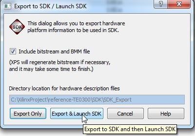 Image Removed Image Removed |
- A new pop-up will appear. Select a proper workspace: for example C:\XilinxProject\reference-TE0300\SDK\SDK_Workspace
| Scroll pdf title |
|---|
|
 Image Removed Image Removed |
| Tip |
|---|
The HW implementation usually takes some time; if you have a very slow computer, the new synthesis could require an hour. |
- After some times the project is eported from XPS to SDK. system.xml is exported in the hw folder of and SDK project. C:\XilinxProject\reference-TE0300\SDK\SDK_Export\hw\system.xml
(1)xxx is
- 300 for TE0300 project: unfortunately they are in the same folder TE03xx
- 320 for TE0320 project: unfortunately they are in the same folder TE03xx
- 630 for TE0630 project
B) Update the SDK project (add more than 10 images)
When Xilinx SDK open, you should:
1) Set the repositories for device driver of custom block used in SDK Microblaze project
- click Xilinx "Xilinx Tools" and then "Repositories"
| Scroll pdf title |
|---|
| title | XilinxSDKProjectRepositories |
|---|
|
 Image Removed Image Removed |
- after this a pop-up "Preferences" will appears
| Scroll pdf title |
|---|
| title | Add Reference Repositories for custom driver of custom block/device |
|---|
|
 Image Removed Image Removed |
...
| Choice assumed in this step and in the following ones. |
|
From now on, the choice (1) is assumed. |
Check the firmware of FX2 microcontroler | Anchor |
|---|
| CheckFX2Firmware |
|---|
| CheckFX2Firmware |
|---|
|
The FX2 microcontroller on the TE USB FX2 module should contain valid firmware before proceeding.
...
| Scroll pdf title |
|---|
| title | Add reference with double indirection (as required by Xilinx SDK) |
|---|
|
 Image Removed Image Removed |
- click "Apply"
- you should click "OK"
- after this you must wait until the building procedure ended.
2) Create an Hardware Platform Specification Project
- You should click "File" >"New" > "Project"
| Scroll pdf title |
|---|
| title | Xilinx SDK New Project |
|---|
|
 Image Removed Image Removed |
- a pop up "New Project" will appears
- click"Xilinx">"Hardware Platform Specification", then next
| Scroll pdf title |
|---|
| title | Xilinx SDK new HW Platform Specification |
|---|
|
 Image Removed Image Removed |
- a new pop up "New Hardware Project" will appear
| Scroll pdf title |
|---|
| title | Xilinx SDK HW Project New Wizard 1 |
|---|
|
 Image Removed Image Removed |
- under "Target Hardware Specification" click "Browse..." button
- a new pop up "Hardware Specification File" will appear
 Image Removed
- select "system.xml", "C:\XilinxProject\reference-TE0300\SDK\SDK_Export\hw\system.xml"
- after the selection a new hardware specification (with name "reference-TE0300_hw_platform") appears in the Procject Explorer of SDK.
| Scroll pdf title |
|---|
|
 Image Removed Image Removed |
3) Create a Board Support Package Project
- You should click "File" >"New" > "Project"
- a pop up "New Project" will appears
- click"Xilinx">"Board Support Package", then next
- a new pop up "New Board Support Package Project" will appear;
| Scroll pdf title |
|---|
| title | New Xilinx Board Support Packages |
|---|
|
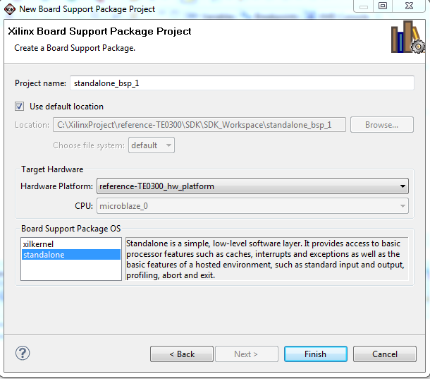 Image Removed Image Removed |
- select "standalone" for "Board Support Package OS" and "standalone_bsp_0" for the "Project name"
- a new pop-up will appear "Board Support Package Settings"
| Scroll pdf title |
|---|
|
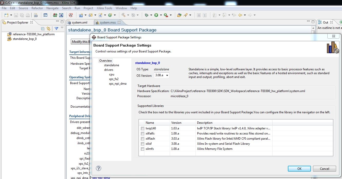 Image Removed Image Removed |
- after this you should click "standalone" and set "stdin" and "stdout" to "rs232" or "debug_module"
- you should select "rs232" if you desire to use an external UART
- you should select "debug_module" if you desire that the XMD_UART works as local UART through the JTAG connection
| Tip |
|---|
| Demo program (running on MicroBlaze) will work even in case the UART port is left unconnected: it is not necessary to use a USB/Uart converter or Uart port on a PC, if you are using XMD UART HDL block. |
| Scroll pdf title |
|---|
| title | BSP rs232 or debug_module |
|---|
|
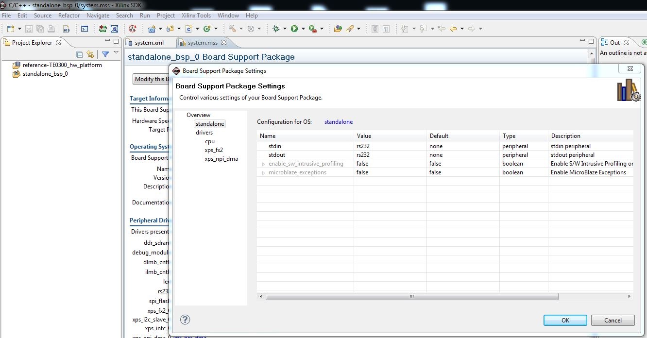 Image Removed Image Removed |
- after this you should click drivers to verify that all Microblaze components are supported by the driver in the repository C:\XilinxProject\TE-EDK-IP; click "OK" and the pop-up should dissapears;
| Scroll pdf title |
|---|
| title | BSP drivers for Microblaze components |
|---|
|
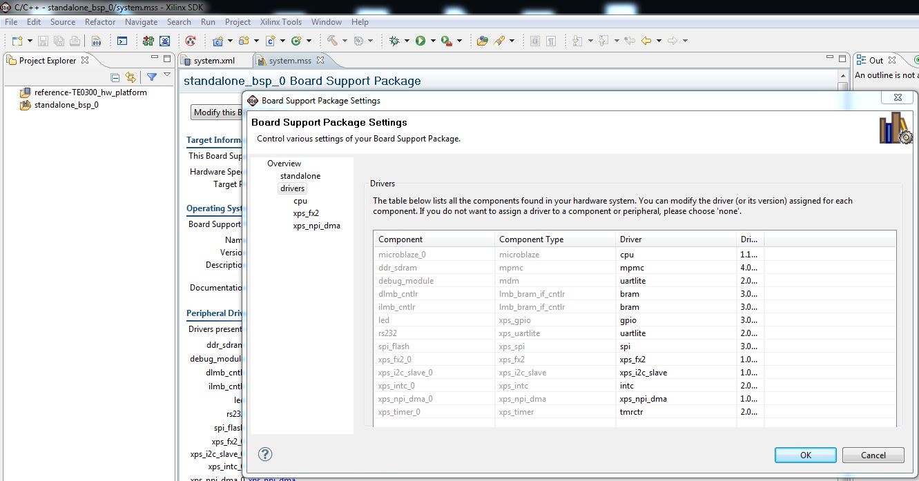 Image Removed Image Removed |
- after you have verified that all Microblaze components are supported by a driver, right click the "standalone_bsp_0" folder in "Project Explorer" and
- the pop-up "Properties for standalone_bsp_0" should appears
- click "Project References"
- you must verify that "standalone_bsp_0" references to "reference-TE0300_hw_platform":if is not checked you must check the box.
| Scroll pdf title |
|---|
| title | "standalone_bsp_0" Project References |
|---|
|
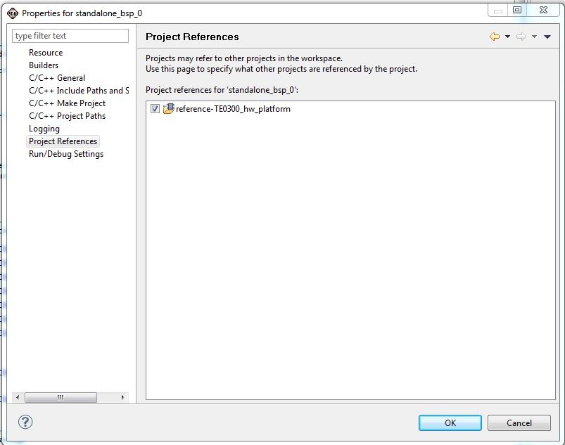 Image Removed Image Removed |
- the FX2 microcontroller on the TE0300, TE0320 or TE0630 family should contain valid firmware before proceeding. If the FX2 microcontroller has not been programmed before, please follow the instructions in the ????? family User Manualshere and here. You can use Cypress, Python OpenFut or C# OpenFutNet programs.
- If you are sure that the FX2 microcontroller is properly connected, you can connect to the TE0300/TE0320/TE0630 TE USB FX2 module with a JTAG adapter cable. We recommend using the Xilinx Platform Cable USB.
- Then connect the TE0300/TE0320/TE0630 TE USB FX2 module to a USB cable.
...
...