Page History
| Page properties | ||||
|---|---|---|---|---|
| ||||
Template Revision 2.8 - on construction Design Name always "TE Series Name" + Design name, for example "TE0720 Test Board" |
| HTML |
|---|
<!-- Template Revision 1.4.1 Basic Notes - export PDF to download, if vivado revision is changed! - Template is for different design and SDSoC and examples, remove unused or wrong description! --> |
| Scroll Only (inline) |
|---|
Online version of this manual and other related documents can be found at https://wiki.trenz-electronic.de/display/PD/Trenz+Electronic+Documentation |
| Scroll pdf ignore | ||||
|---|---|---|---|---|
Table of contents
|
Overview
| HTML |
|---|
<!--
General Design description
--> |
Design example with Linux and MGT-CLK frequency monitoring over VIO.
Key Features
| HTML |
|---|
<!--
Add Basic Key Features of the design (should be tested)
--> |
| Excerpt |
|---|
|
Revision History
| HTML |
|---|
<!--
- Add changes from design
- Export PDF to download, if vivado revision is changed!
--> |
...
- initial release
Release Notes and Know Issues
| HTML |
|---|
<!--
- add known Design issues and general Notes for the current revision
--> |
...
Requirements
Software
| HTML |
|---|
<!--
Add needed external Software
--> |
...
Hardware
| HTML |
|---|
<!--
Hardware Support
--> |
Basic description of TE Board Part Files is available on TE Board Part Files.
Complete List is available on <design name>/board_files/*_board_files.csv
Design supports following modules:
...
- reduced DDR speed for ES Variant
- Xilinx has stopped ES1 support with 2018.2, please use 2017.1 reference design
...
Additional HW Requirements:
...
Content
| HTML |
|---|
<!--
Remove unused content
--> |
For general structure and of the reference design, see Project Delivery
Design Sources
...
tables have all same width (web max 1200px and pdf full page(640px), flexible width or fix width on menu for single column can be used as before) -->
<style>
.wrapped{
  width: 100% !important;
  max-width: 1200px !important;
 }
</style> |
| Page properties | ||||||||||||||||||||||||||||||||||||||||
|---|---|---|---|---|---|---|---|---|---|---|---|---|---|---|---|---|---|---|---|---|---|---|---|---|---|---|---|---|---|---|---|---|---|---|---|---|---|---|---|---|
| ||||||||||||||||||||||||||||||||||||||||
Important General Note:
|
| Scroll pdf ignore | ||||
|---|---|---|---|---|
Table of contents
|
Overview
| Page properties | ||||
|---|---|---|---|---|
| ||||
Notes :
|
Design example with Linux and MGT-CLK frequency monitoring over VIO.
Refer to http://trenz.org/teb0911-info for the current online version of this manual and other available documentation.
Key Features
| Page properties | ||||
|---|---|---|---|---|
| ||||
Notes :
|
| Excerpt |
|---|
|
Revision History
| Page properties | ||||
|---|---|---|---|---|
| ||||
Notes :
|
| Scroll Title | |||||||||||||||||||||||||||||||||||||||||||||||||||||
|---|---|---|---|---|---|---|---|---|---|---|---|---|---|---|---|---|---|---|---|---|---|---|---|---|---|---|---|---|---|---|---|---|---|---|---|---|---|---|---|---|---|---|---|---|---|---|---|---|---|---|---|---|---|
| |||||||||||||||||||||||||||||||||||||||||||||||||||||
|
Release Notes and Know Issues
| Page properties | ||||
|---|---|---|---|---|
| ||||
Notes :
|
| Scroll Title | ||||||||||||||||||||||||||
|---|---|---|---|---|---|---|---|---|---|---|---|---|---|---|---|---|---|---|---|---|---|---|---|---|---|---|
| ||||||||||||||||||||||||||
|
Requirements
Software
| Page properties | ||||
|---|---|---|---|---|
| ||||
Notes :
|
| Scroll Title | ||||||||||||||||||||||||||||||
|---|---|---|---|---|---|---|---|---|---|---|---|---|---|---|---|---|---|---|---|---|---|---|---|---|---|---|---|---|---|---|
| ||||||||||||||||||||||||||||||
|
Hardware
| Page properties | ||||
|---|---|---|---|---|
| ||||
Notes :
|
Basic description of TE Board Part Files is available on TE Board Part Files.
Complete List is available on <design name>/board_files/*_board_files.csv
Design supports following modules:
| Scroll Title | ||||||||||||||||||||||||||||||||||||||||||||||||||||||||||||||||||||||||||||||||||
|---|---|---|---|---|---|---|---|---|---|---|---|---|---|---|---|---|---|---|---|---|---|---|---|---|---|---|---|---|---|---|---|---|---|---|---|---|---|---|---|---|---|---|---|---|---|---|---|---|---|---|---|---|---|---|---|---|---|---|---|---|---|---|---|---|---|---|---|---|---|---|---|---|---|---|---|---|---|---|---|---|---|---|
| ||||||||||||||||||||||||||||||||||||||||||||||||||||||||||||||||||||||||||||||||||
|
Additional HW Requirements:
| Scroll Title | ||||||||||||||||||||||
|---|---|---|---|---|---|---|---|---|---|---|---|---|---|---|---|---|---|---|---|---|---|---|
| ||||||||||||||||||||||
|
Content
| Page properties | ||||
|---|---|---|---|---|
| ||||
Notes :
|
For general structure and of the reference design, see Project Delivery - AMD devices
Design Sources
| Scroll Title | ||||||||||||||||||||||||||||||
|---|---|---|---|---|---|---|---|---|---|---|---|---|---|---|---|---|---|---|---|---|---|---|---|---|---|---|---|---|---|---|
| ||||||||||||||||||||||||||||||
|
Additional Sources
| Scroll Title | ||||||||||||||||||||||||||||||
|---|---|---|---|---|---|---|---|---|---|---|---|---|---|---|---|---|---|---|---|---|---|---|---|---|---|---|---|---|---|---|
| ||||||||||||||||||||||||||||||
|
Prebuilt
| Page properties | ||||||||||||||||||||||||||||||||||
|---|---|---|---|---|---|---|---|---|---|---|---|---|---|---|---|---|---|---|---|---|---|---|---|---|---|---|---|---|---|---|---|---|---|---|
| ||||||||||||||||||||||||||||||||||
Notes :
|
Additional Sources
...
Prebuilt
| HTML |
|---|
<!--

<table width="100%">
<tr> <th>File                                 </th> <th>File-Extension</th>  <th>Description                                                                              </th> </tr>
<tr> <td>BIF-File                             </td> <td>*.bif         </td>  <td>File with description to generate Bin-File                                               </td> </tr>
<tr> <td>BIN-File                             </td> <td>*.bin         </td>  <td>Flash Configuration File with Boot-Image (Zynq-FPGAs)                                    </td> </tr>
<tr> <td>BIT-File                             </td> <td>*.bit         </td>  <td>FPGA Configuration File                                                                  </td> </tr>
<tr> <td>DebugProbes-File                     </td> <td>*.ltx         </td>  <td>Definition File for Vivado/Vivado Labtools Debugging Interface                           </td> </tr>
<tr> <td>Debian SD-Image                      </td> <td>*.img         </td>  <td>Debian Image for SD-Card                                                                </td> </tr>
<tr> <td>Diverse Reports                      </td> <td>  ---         </td>  <td>Report files in different formats                                                        </td> </tr>
<tr> <td>Hardware-Platform-Specification-Files</td> <td>*.hdf         </td>  <td>Exported Vivado Hardware Specification for SDK/HSI                                       </td> </tr>
<tr> <td>LabTools Project-File                </td> <td>*.lpr         </td>  <td>Vivado Labtools Project File                                                             </td> </tr>
<tr> <td>MCS-File                             </td> <td>*.mcs         </td>  <td>Flash Configuration File with Boot-Image (MicroBlaze or FPGA part only)                  </td> </tr>
<tr> <td>MMI-File                             </td> <td>*.mmi         </td>  <td>File with BRAM-Location to generate MCS or BIT-File with *.elf content (MicroBlaze only) </td> </tr>
<tr> <td>OS-Image                             </td> <td>*.ub          </td>  <td>Image with Linux Kernel (On Petalinux optional with Devicetree and RAM-Disk)             </td> </tr>
<tr> <td>Software-Application-File            </td> <td>*.elf         </td>  <td>Software Application for Zynq or MicroBlaze Processor Systems                            </td> </tr>
<tr> <td>SREC-File                            </td> <td>*.srec        </td>  <td>Converted Software Application for MicroBlaze Processor Systems                          </td> </tr>
</table>
-->
|
...
File
...
File-Extension
...
Description
...
|
...
|
...
|
Download
Reference Design is only usable with the specified Vivado/SDK/PetaLinux/SDx version. Do never use different Versions of Xilinx Software for the same Project.
| HTML |
|---|
<!--
Add correct path:https://shop.trenz-electronic.de/en/Download/?path=Trenz_Electronic/TE0803/Reference_Design/2017.1/Starterkit
--> |
Reference Design is available on:
Design Flow
| HTML |
|---|
<!--
Basic Design Steps
Add/ Remove project specific
--> |
| Note |
|---|
Reference Design is available with and without prebuilt files. It's recommended to use TE prebuilt files for first lunch. |
Trenz Electronic provides a tcl based built environment based on Xilinx Design Flow.
See also:
The Trenz Electronic FPGA Reference Designs are TCL-script based project. Command files for execution will be generated with "_create_win_setup.cmd" on Windows OS and "_create_linux_setup.sh" on Linux OS.
TE Scripts are only needed to generate the vivado project, all other additional steps are optional and can also executed by Xilinx Vivado/SDK GUI. For currently Scripts limitations on Win and Linux OS see: Project Delivery Currently limitations of functionality
- _create_win_setup.cmd/_create_linux_setup.sh and follow instructions on shell:
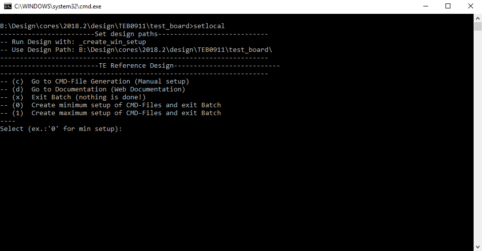
- Press 0 and enter for minimum setup
- (optional Win OS) Generate Virtual Drive or use short directory for the reference design (for example x:\<design name>)
- Create Project
- Select correct device and Xilinx install path on "design_basic_settings.cmd" and create Vivado project with "vivado_create_project_guimode.cmd"
Note: Select correct one, see TE Board Part Files
- Select correct device and Xilinx install path on "design_basic_settings.cmd" and create Vivado project with "vivado_create_project_guimode.cmd"
- Create HDF and export to prebuilt folder
- Run on Vivado TCL: TE::hw_build_design -export_prebuilt
Note: Script generate design and export files into \prebuilt\hardware\<short dir>. Use GUI is the same, except file export to prebuilt folder
- Run on Vivado TCL: TE::hw_build_design -export_prebuilt
- Create Linux (uboot.elf and image.ub) with exported HDF
- HDF is exported to "prebuilt\hardware\<short name>"
Note: HW Export from Vivado GUI create another path as default workspace. - Create Linux images on VM, see PetaLinux KICKstart
- Use TE Template from /os/petalinux
Note: run init_config.sh before you start petalinux config. This will set correct temporary path variable.
- Use TE Template from /os/petalinux
- HDF is exported to "prebuilt\hardware\<short name>"
- Add Linux files (uboot.elf and image.ub) to prebuilt folder
- "prebuilt\os\petalinux\default" or "prebuilt\os\petalinux\<short name>"
Notes: Scripts select "prebuilt\os\petalinux\<short name>", if exist, otherwise "prebuilt\os\petalinux\default"
- "prebuilt\os\petalinux\default" or "prebuilt\os\petalinux\<short name>"
- Generate Programming Files with HSI/SDK
- Run on Vivado TCL: TE::sw_run_hsi
Note: Scripts generate applications and bootable files, which are defined in "sw_lib\apps_list.csv" - (alternative) Start SDK with Vivado GUI or start with TE Scripts on Vivado TCL: TE::sw_run_sdk
Note: See SDK Projects
- Run on Vivado TCL: TE::sw_run_hsi
Launch
Programming
| HTML |
|---|
<!--
Description of Block Design, Constrains...
BD Pictures from Export...
--> |
| Note |
|---|
Check Module and Carrier TRMs for proper HW configuration before you try any design. |
Xilinx documentation for programming and debugging: Vivado/SDK/SDSoC-Xilinx Software Programming and Debugging
QSPI
Optional for Boot.bin on QSPI Flash and image.ub on SD.
- Connect JTAG and power on carrier with module
- Open Vivado Project with "vivado_open_existing_project_guimode.cmd" or if not created, create with "vivado_create_project_guimode.cmd"
- Type on Vivado TCL Console: TE::pr_program_flash_binfile -swapp u-boot
Note: To program with SDK/Vivado GUI, use special FSBL (zynqmp_fsbl_flash) on setup
Optional "TE::pr_program_flash_binfile -swapp hello_te0803" possible - Copy image.ub on SD-Card
- For correct prebuilt file location, see <design_name>/prebuilt/readme_file_location.txt
- Insert SD-Card
SD
- Copy image.ub and Boot.bin on SD-Card.
- For correct prebuilt file location, see <design_name>/prebuilt/readme_file_location.txt
- Set Boot Mode to SD-Boot.
- Depends on CPLD Firmware, see SC0911 CPLD#BootMode
- Insert SD-Card in SD-Slot.
JTAG
Not used on this Example.
Usage
- Prepare HW like described on section Programming
- Connect UART USB (same as FPGA JTAG)
- Select SD Card as Boot Mode (or QSPI - depending on step 1)
- (Optional) Insert PCIe Card (detection depends on Linux driver. Only some basic drivers are installed)
- (Optional) Connect DisplayPort Monitor (List of usable Monitors: https://www.xilinx.com/support/answers/68671.html)
- (Optional) Connect Network Cable
- Power On PCB
Note: 1. ZynqMP Boot ROM loads PMU Firmware and FSBL from SD into OCM, 2. FSBL loads ATF(bl31.elf) and U-boot from SD/QSPI into DDR, 3. U-boot load Linux from SD into DDR.
Linux
- Open Serial Console (e.g. putty)
- Speed: 115200
- COM Port: Win OS, see device manager, Linux OS see dmesg |grep tty (UART is *USB1)
- Linux Console:
Note: Wait until Linux boot finished For Linux Login use:- User Name: root
- Password: root
- You can use Linux shell now.
- I2C 0 Bus type: i2cdetect -y -r 0
- ETH0 works with udhcpc
- USB type "lsusb" or connect USB device
- PCIe type "lspci"
Vivado HW Manager
(coming soon)
System Design - Vivado
| HTML |
|---|
<!--
Description of Block Design, Constrains...
BD Pictures from Export...
--> |
Block Design
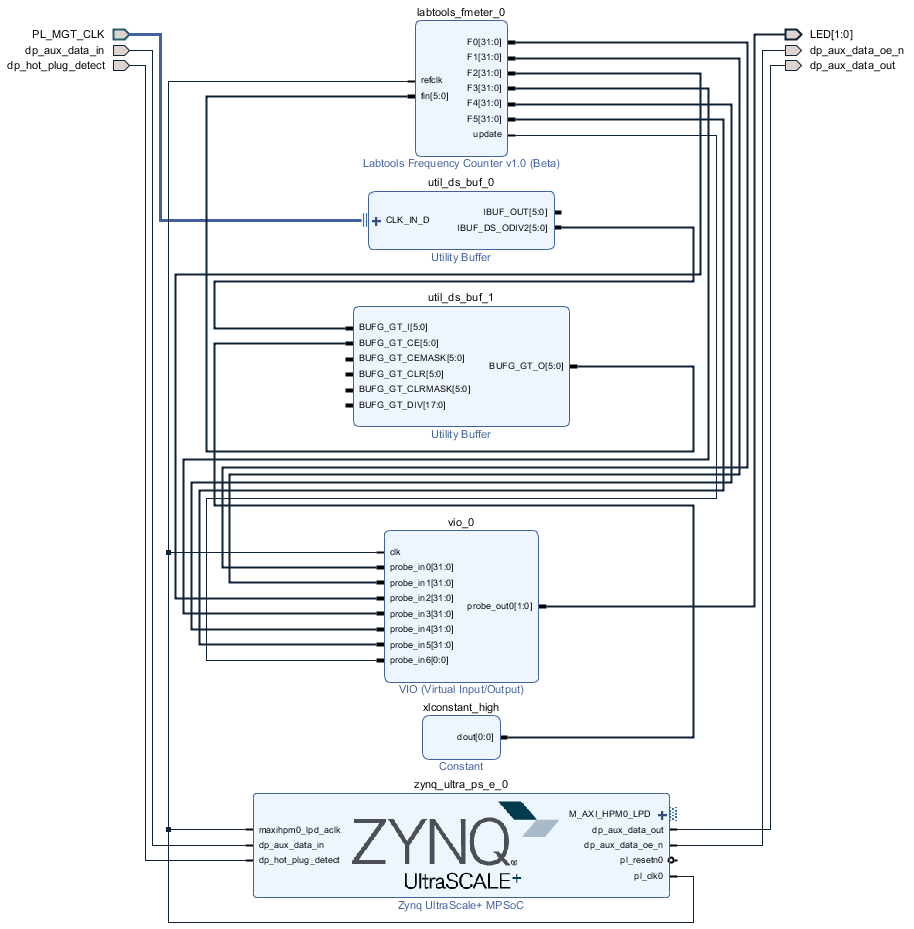
PS Interfaces
Activated interfaces:
...
|
| Scroll Title | ||||||||||||||||||||||||||||||||||||||||||||||||
|---|---|---|---|---|---|---|---|---|---|---|---|---|---|---|---|---|---|---|---|---|---|---|---|---|---|---|---|---|---|---|---|---|---|---|---|---|---|---|---|---|---|---|---|---|---|---|---|---|
| ||||||||||||||||||||||||||||||||||||||||||||||||
|
Download
Reference Design is only usable with the specified Vivado/SDK/PetaLinux/SDx version. Do never use different Versions of Xilinx Software for the same Project.
| Page properties | ||||
|---|---|---|---|---|
| ||||
|
Reference Design is available on:
Design Flow
| Page properties | ||||
|---|---|---|---|---|
| ||||
Notes :
|
| Note |
|---|
Reference Design is available with and without prebuilt files. It's recommended to use TE prebuilt files for first lunch. |
Trenz Electronic provides a tcl based built environment based on Xilinx Design Flow.
See also:
- AMD Development Tools#XilinxSoftware-BasicUserGuides
- Vivado Projects - TE Reference Design
- Project Delivery.
The Trenz Electronic FPGA Reference Designs are TCL-script based project. Command files for execution will be generated with "_create_win_setup.cmd" on Windows OS and "_create_linux_setup.sh" on Linux OS.
TE Scripts are only needed to generate the vivado project, all other additional steps are optional and can also executed by Xilinx Vivado/SDK GUI. For currently Scripts limitations on Win and Linux OS see: Project Delivery Currently limitations of functionality
- _create_win_setup.cmd/_create_linux_setup.sh and follow instructions on shell:
- Press 0 and enter to start "Module Selection Guide"
- (optional Win OS) Generate Virtual Drive or use short directory for the reference design (for example x:\<design name>)
- Create Project (follow instruction of the product selection guide), settings file will be configured automatically during this process
- (optional for manual changes) Select correct device and Xilinx install path on "design_basic_settings.cmd" and create Vivado project with "vivado_create_project_guimode.cmd"
Note: Select correct one, see alsoTE Board Part Files
- (optional for manual changes) Select correct device and Xilinx install path on "design_basic_settings.cmd" and create Vivado project with "vivado_create_project_guimode.cmd"
- Create HDF and export to prebuilt folder
- Run on Vivado TCL: TE::hw_build_design -export_prebuilt
Note: Script generate design and export files into \prebuilt\hardware\<short dir>. Use GUI is the same, except file export to prebuilt folder
- Run on Vivado TCL: TE::hw_build_design -export_prebuilt
- Create Linux (uboot.elf and image.ub) with exported XSA
- XSAis exported to "prebuilt\hardware\<short name>"
Note: HW Export from Vivado GUI create another path as default workspace. - Create Linux images on VM, see PetaLinux KICKstart
- Use TE Template from /os/petalinux
- XSAis exported to "prebuilt\hardware\<short name>"
- Add Linux files (uboot.elf and image.ub) to prebuilt folder
- "prebuilt\os\petalinux\<ddr size>" or "prebuilt\os\petalinux\<short name>"
- Generate Programming Files with Vitis
- Run on Vivado TCL: TE::sw_run_vitis -all
Note: Scripts generate applications and bootable files, which are defined in "sw_lib\apps_list.csv" - (alternative) Start SDK with Vivado GUI or start with TE Scripts on Vivado TCL: TE::sw_run_vitis
Note: TCL scripts generate also platform project, this must be done manuelly in case GUI is used. See Vitis
- Run on Vivado TCL: TE::sw_run_vitis -all
Launch
| Page properties | ||||
|---|---|---|---|---|
| ||||
Note:
|
Programming
| Note |
|---|
Check Module and Carrier TRMs for proper HW configuration before you try any design. |
Xilinx documentation for programming and debugging: Vivado/SDK/SDSoC-Xilinx Software Programming and Debugging
Get prebuilt boot binaries
- _create_win_setup.cmd/_create_linux_setup.sh and follow instructions on shell
- Press 0 and enter to start "Module Selection Guide"
- Select assembly version
- Validate selection
- Select Create and open delivery binary folder
Note: Folder (<project foler>/_binaries_<Artikel Name>) with subfolder (boot_<app name>) for different applications will be generated
QSPI
Optional for Boot.bin on QSPI Flash and image.ub on SD.
- Connect JTAG and power on carrier with module
- Open Vivado Project with "vivado_open_existing_project_guimode.cmd" or if not created, create with "vivado_create_project_guimode.cmd"
- Type on Vivado TCL Console: TE::pr_program_flash_binfile -swapp u-boot
Note: To program with SDK/Vivado GUI, use special FSBL (zynqmp_fsbl_flash) on setup
Optional "TE::pr_program_flash_binfile -swapp hello_teb0911" possible - Copy image.ub and optional misc/sd/init.sh on SD-Card
- use files from (<project foler>/_binaries_<Articel Name>)/boot_linux from generated binary folder,see: Get prebuilt boot binaries
- or use prebuilt file location, see <design_name>/prebuilt/readme_file_location.txt
- Insert SD-Card
SD
- Copy image.ub, Boot.bin and misc/sd/init.sh on SD-Card.
- use files from (<project foler>/_binaries_<Articel Name>)/boot_linux from generated binary folder,see: Get prebuilt boot binaries
- or use prebuilt file location, see <design_name>/prebuilt/readme_file_location.txt
- Set Boot Mode to SD-Boot.
- Depends on CPLD Firmware, see SC0911 CPLD#BootMode
- Insert SD-Card in SD-Slot.
JTAG
Not used on this Example.
Usage
- Prepare HW like described on section 70156312
- Connect UART USB (same as FPGA JTAG)
- Select SD Card as Boot Mode (or QSPI - depending on step 1)
- (Optional) Insert PCIe Card (detection depends on Linux driver. Only some basic drivers are installed)
- (Optional) Connect DisplayPort Monitor (List of usable Monitors: https://www.xilinx.com/support/answers/68671.html)
- (Optional) Connect Network Cable
- Power On PCB
Note: 1. ZynqMP Boot ROM loads PMU Firmware and FSBL from SD into OCM, 2. FSBL loads ATF(bl31.elf) and U-boot from SD/QSPI into DDR, 3. U-boot load Linux from SD into DDR.
Linux
- Open Serial Console (e.g. putty)
- Speed: 115200
- COM Port: Win OS, see device manager, Linux OS see dmesg |grep tty (UART is *USB1)
- Linux Console:
Note: Wait until Linux boot finished For Linux Login use:- User Name: root
- Password: root
- You can use Linux shell now.
- I2C 0 Bus type: i2cdetect -y -r 0
- ETH0 works with udhcpc
- USB type "lsusb" or connect USB device
- PCIe type "lspci"
Vivado HW Manager
| Page properties | ||||
|---|---|---|---|---|
| ||||
Note:
|
Control:
- User LED Control (D16, D15)
Monitoring:
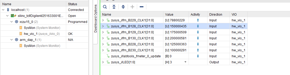
- MGT CLK Measurement:
- Open Vivado HW-Manager and add VIO signal to dashboard (*.ltx located on prebuilt folder).Set radix from VIO signals to unsigned integer.Note: Frequency Counter is inaccurate and displayed unit is Hz
- Default B229_CLK1: 78,8MHz, B128_CLK1: 150MHz, B129_CLK1: 175MHz, B130_CLK1: 200MHz, B228_CLK1: 125MHz, B23ß_CLK1: 100MHz
| Scroll Title | ||||
|---|---|---|---|---|
| ||||
 |
System Design - Vivado
| Page properties | ||||
|---|---|---|---|---|
| ||||
Note:
|
Block Design
| Scroll Title | ||||
|---|---|---|---|---|
| ||||
|
PS Interfaces
| Page properties | ||||
|---|---|---|---|---|
| ||||
Note:
|
Activated interfaces:
| Scroll Title | ||||||||||||||||||||||||||||||||||||||||||||||||
|---|---|---|---|---|---|---|---|---|---|---|---|---|---|---|---|---|---|---|---|---|---|---|---|---|---|---|---|---|---|---|---|---|---|---|---|---|---|---|---|---|---|---|---|---|---|---|---|---|
| ||||||||||||||||||||||||||||||||||||||||||||||||
|
Constrains
Basic module constrains
| Code Block | ||||
|---|---|---|---|---|
| ||||
set_property BITSTREAM.GENERAL.COMPRESS TRUE [current_design]
set_property BITSTREAM.CONFIG.UNUSEDPIN PULLNONE [current_design] |
Design specific constrain
| Code Block | ||||
|---|---|---|---|---|
| ||||
# GT Clocks
#B128-1
set_property PACKAGE_PIN N27 [get_ports {PL_MGT_CLK_clk_p[0]}]
#B129-1
set_property PACKAGE_PIN J27 [get_ports {PL_MGT_CLK_clk_p[1]}]
#B228-1
set_property PACKAGE_PIN J8  [get_ports {PL_MGT_CLK_clk_p[2]}]
#B130-1
set_property PACKAGE_PIN E27 [get_ports {PL_MGT_CLK_clk_p[3]}]
#B229-1
set_property PACKAGE_PIN E8  [get_ports {PL_MGT_CLK_clk_p[4]}]
#B230-1
set_property PACKAGE_PIN B10 [get_ports {PL_MGT_CLK_clk_p[5]}]

## DP
set_property PACKAGE_PIN AB1 [get_ports dp_aux_data_in]
set_property PACKAGE_PIN V9 [get_ports dp_hot_plug_detect]
set_property PACKAGE_PIN AA8 [get_ports dp_aux_data_out]
set_property PACKAGE_PIN AA3  [get_ports dp_aux_data_oe_n]
set_property IOSTANDARD LVCMOS18 [get_ports dp_*]
## LED
set_property PACKAGE_PIN K14 [get_ports {LED[0]}]
set_property PACKAGE_PIN K10 [get_ports {LED[1]}]
set_property IOSTANDARD LVCMOS18 [get_ports {LED*}]
|
Software Design - Vitis
| Page properties | ||||
|---|---|---|---|---|
| ||||
Note:
|
For SDK project creation, follow instructions from:
Application
SDK template in ./sw_lib/sw_apps/ available.
| Page properties | ||||
|---|---|---|---|---|
| ||||
---------------------------------------------------------- FPGA Example scuMCS Firmware to configure SI5338 and Reset System. srec_spi_bootloaderTE modified 2019.2 SREC Bootloader to load app or second bootloader from flash into DDR Descriptions:
xilisf_v5_11TE modified 2019.2 xilisf_v5_11
---------------------------------------------------------- Zynq Example: zynq_fsblTE modified 2019.2 FSBL General:
Module Specific:
zynq_fsbl_flashTE modified 2019.2 FSBL General:
ZynqMP Example: ---------------------------------------------------------- zynqmp_fsblTE modified 2019.2 FSBL General:
Module Specific:
zynqmp_fsbl_flashTE modified 2019.2 FSBL General:
zynqmp_pmufwXilinx default PMU firmware. ---------------------------------------------------------- General Example: hello_te0820Hello TE0820 is a Xilinx Hello World example as endless loop instead of one console output. u-bootU-Boot.elf is generated with PetaLinux. Vitis is used to generate Boot.bin. |
zynqmp_fsbl
TE modified 2019.2 FSBL
General:
- Modified Files: xfsbl_main.c, xfsbl_hooks.h/.c, xfsbl_board.h/.c(search for 'TE Mod' on source code)
- Add Files: te_xfsbl_hooks.h/.c (for hooks and board)\n\
- General Changes:
- Display FSBL Banner and Device Name
Module Specific:
- Add Files: all TE Files start with te_*
- Si5338 and SI5345 Configuration
- PCIe reset
zynqmp_fsbl_flash
TE modified 2019.2 FSBL
General:
- Modified Files: xfsbl_initialisation.c, xfsbl_hw.h, xfsbl_handoff.c, xfsbl_main.c
- General Changes:
- Display FSBL Banner
- Set FSBL Boot Mode to JTAG
- Disable Memory initialisation
zynqmp_pmufw
Xilinx default PMU firmware.
hello_teb0911
Hello TEB0911 is a Xilinx Hello World example as endless loop instead of one console output.
u-boot
U-Boot.elf is generated with PetaLinux. SDK/HSI is used to generate Boot.bin.
Software Design - PetaLinux
| Page properties | ||||
|---|---|---|---|---|
| ||||
Note:
|
For PetaLinux installation and project creation, follow instructions from:
Config
Start with petalinux-config or petalinux-config --get-hw-description
Changes:
- SUBSYSTEM_PRIMARY_SD_PSU_SD_1_SELECT
- CONFIG_SUBSYSTEM_ETHERNET_PSU_ETHERNET_3_MAC=""
U-Boot
Start with petalinux-config -c u-boot
Changes:
- CONFIG_ENV_IS_NOWHERE=y
- # CONFIG_ENV_IS_IN_SPI_FLASH is not set
- CONFIG_I2C_EEPROM=y
- CONFIG_ZYNQ_GEM_I2C_MAC_OFFSET=0xFA
- CONFIG_SYS_I2C_EEPROM_ADDR=0x54
- CONFIG_SYS_I2C_EEPROM_BUS=5
- CONFIG_SYS_EEPROM_SIZE=256
- CONFIG_SYS_EEPROM_PAGE_WRITE_BITS=0
- CONFIG_SYS_EEPROM_PAGE_WRITE_DELAY_MS=0
- CONFIG_SYS_I2C_EEPROM_ADDR_LEN=1
- CONFIG_SYS_I2C_EEPROM_ADDR_OVERFLOW=0
Change platform-top.h
| Code Block | ||
|---|---|---|
| ||
Device Tree
| Code Block | ||
|---|---|---|
| ||
/include/ "system-conf.dtsi"
/ {
  chosen {
    xlnx,eeprom = &eeprom;
  };
};

/* USB  */

&dwc3_0 {
    status = "okay";
    dr_mode = "host";
    snps,usb3_lpm_capable;
    snps,dis_u3_susphy_quirk;
    snps,dis_u2_susphy_quirk;
    phy-names = "usb2-phy","usb3-phy";
    phys = <&lane1 4 0 1 100000000>;
    maximum-speed = "super-speed";
};


/* QSPI */

&qspi {
|
Constrains
Basic module constrains
| Code Block | ||||
|---|---|---|---|---|
| ||||
set_property BITSTREAM.GENERAL.COMPRESS TRUE [current_design]
set_property BITSTREAM.CONFIG.UNUSEDPIN PULLNONE [current_design] |
Design specific constrain
| Code Block | ||||
|---|---|---|---|---|
| ||||
# GT Clocks
#B128-1
set_property PACKAGE_PIN N27 [get_ports {PL_MGT_CLK_clk_p[0]}]
#B129-1
set_property PACKAGE_PIN J27 [get_ports {PL_MGT_CLK_clk_p[1]}]
#B228-1
set_property PACKAGE_PIN J8  [get_ports {PL_MGT_CLK_clk_p[2]}]
#B130-1
set_property PACKAGE_PIN E27 [get_ports {PL_MGT_CLK_clk_p[3]}]
#B229-1
set_property PACKAGE_PIN E8  [get_ports {PL_MGT_CLK_clk_p[4]}]
#B230-1
set_property PACKAGE_PIN B10 [get_ports {PL_MGT_CLK_clk_p[5]}]

## DP
set_property PACKAGE_PIN AB1 [get_ports dp_aux_data_in]
set_property PACKAGE_PIN V9 [get_ports dp_hot_plug_detect]
set_property PACKAGE_PIN AA8 [get_ports dp_aux_data_out]
set_property PACKAGE_PIN AA3  [get_ports dp_aux_data_oe_n]
set_property IOSTANDARD LVCMOS18 [get_ports dp_*]
## LED
set_property PACKAGE_PIN K14 [get_ports {LED[0]}]
set_property PACKAGE_PIN K10 [get_ports {LED[1]}]
set_property IOSTANDARD LVCMOS18 [get_ports {LED*}]
|
Software Design - SDK/HSI
| HTML |
|---|
<!--
optional chapter
separate sections for different apps
--> |
For SDK project creation, follow instructions from:
Application
SDK template in ./sw_lib/sw_apps/ available.
zynqmp_fsbl
TE modified 2018.2 FSBL
Changes:
- Si5345Configuration
- see xfsbl_board.c and xfsbl_board.h, xfsbl_main.c
- Add Si5345-Registers.h, si5345.c, si5345.h, si5338.c, si5338.h, register_map.h
Note: Remove compiler flags "-Os -flto -ffat-lto-objects" on 2018.2 SDK to generate FSBL
zynqmp_fsbl_flash
TE modified 2018.2 FSBL
Changes:
- Set FSBL Boot Mode to JTAG
- Disable Memory initialisation
Note: Remove compiler flags "-Os -flto -ffat-lto-objects" on 2018.2 SDK to generate FSBL
zynqmp_pmufw
Xilinx default PMU firmware.
hello_teb0911
Hello TEB0911 is a Xilinx Hello World example as endless loop instead of one console output.
u-boot
U-Boot.elf is generated with PetaLinux. SDK/HSI is used to generate Boot.bin.
Software Design - PetaLinux
| HTML |
|---|
<!--
optional chapter
Add "No changes." or "Activate: and add List"
--> |
For PetaLinux installation and project creation, follow instructions from:
Config
Activate:
- SUBSYSTEM_PRIMARY_SD_PSU_SD_1_SELECT
U-Boot
Change platform-top.h
| Code Block | ||
|---|---|---|
| ||
#include <configs/platform-auto.h>
#define CONFIG_SYS_BOOTM_LEN 0xF000000

#define DFU_ALT_INFO_RAM \
                "dfu_ram_info=" \
        "setenv dfu_alt_info " \
        "image.ub ram $netstart 0x1e00000\0" \
        "dfu_ram=run dfu_ram_info && dfu 0 ram 0\0" \
        "thor_ram=run dfu_ram_info && thordown 0 ram 0\0"

#define DFU_ALT_INFO_MMC \
        "dfu_mmc_info=" \
        "set dfu_alt_info " \
        "${kernel_image} fat 0 1\\\\;" \
        "dfu_mmc=run dfu_mmc_info && dfu 0 mmc 0\0" \
        "thor_mmc=run dfu_mmc_info && thordown 0 mmc 0\0"

/*Required for uartless designs */
#ifndef CONFIG_BAUDRATE
#define CONFIG_BAUDRATE 115200
#ifdef CONFIG_DEBUG_UART
#undef CONFIG_DEBUG_UART
#endif
#endif

/*Define CONFIG_ZYNQMP_EEPROM here and its necessaries in u-boot menuconfig if you had EEPROM memory. */
#ifdef CONFIG_ZYNQMP_EEPROM
#define CONFIG_SYS_I2C_EEPROM_ADDR_LEN  1
#define CONFIG_CMD_EEPROM
#define CONFIG_ZYNQ_EEPROM_BUS          5
#define CONFIG_ZYNQ_GEM_EEPROM_ADDR     0x54
#define CONFIG_ZYNQ_GEM_I2C_MAC_OFFSET  0x20
#endif
|
Device Tree
| Code Block | ||
|---|---|---|
| ||
/include/ "system-conf.dtsi" / { }; /* USB */ &dwc3_0 { status = "okay"; dr_mode = "host"; }; /* QSPI */ &qspi { #address-cells = <1>; #size-cells = <0>; status = "okay"; flash0: flash@0 { compatible = "jedec,spi-nor"; reg = <0x0>; #address-cells = <1>; #size-cells = <1>; }; }; /* ETH */ &gem3 { phy-handle = <&phy0>; phy0: phy0@1 { device_type = "ethernet-phy"; reg = <1>; }; }; /* SD1 */ &sdhci1 { // disable-wp; no-1-8-v; }; &i2c0 { i2cswitch@76 { // I2C Switch U13 compatible = "nxp,pca9548"; #address-cells = <1>; #size-cells = <0>; reg = <0x76>; i2c-mux-idle-disconnect; i2c@2 { // FMCD (/dev/i2c-3) #address-cells = <1>; #size-cells = <0>; reg = <2>; }; i2c@3 { // FMCE (/dev/i2c-4) #address-cells = <1>; #size-cells = <0>; reg = <3>; }; i2c@4 { // FMCB (/dev/i2c-5) #address-cells = <1>; #size-cells = <0>; reg = <4>; }; i2c@5 { // FMCC (/dev/i2c-6) #address-cells = <1>; #size-cells = <0>; reg = <5>; }; i2c@6 { // PLL (/dev/i2c-7) #address-cells = <1>; #size-cells = <0>; reg = <6>; si570_2: clock-generator3@5d { #clock-cells = <0>; compatible = "silabs,si570"; reg = <0x5d>; temperature-stability = <50>; factory-fout = <156250000>; clock-frequency = <78800000>; }; }; }; i2cswitch@77 { // I2C Switch U37 compatible = "nxp,pca9548"; #address-cells = <1>; #size-cells = <0>; reg = <0x77>; i2c-mux-idle-disconnect; i2c@0 { // SFP2 (/dev/i2c-9) #address-cells = <1>; #size-cells = <0>; reg = <0>; }; i2c@1 { // FMCA (/dev/i2c-10) #address-cells = <1>; #size-cells = <0>; reg = <1>; }; i2c@2 { // FMCF (/dev/i2c-11) #address-cells = <1>; #size-cells = <0>; reg = <2>; }; i2c@3 { // SFP0 (/dev/i2c-12) #address-cells = <1>; #size-cells = <0>; reg = <3>; }; i2c@4 { // SFP1 (/dev/i2c-13) #address-cells = <1>; #size-cells = <0>; reg = <4>; }; i2c@5 { // MEM (/dev/i2c-14) // Low frequency to work with CPLD clock-frequency = <100000>; #address-cells = <1>; #size-cells = <0>; reg = <5>; }; i2c@6 { // DDR4 (/dev/i2c-15) #address-cells = <1>; #size-cells = <0>; reg = <6>; }; i2c@7 { // USBH (/dev/i2c-16) #address-cells = <1>; #size-cells = <0>; status = "okay"; flash0: flash@0 reg{ = <7>; compatible }; }; }; /* UNUSED DMA disable */ &lpd_dma_chan1 { status = "disabled"; }; &lpd_dma_chan2 { status = "disabled"; }; &lpd_dma_chan3 { status = "disabled"; }; &lpd_dma_chan4 { status = "disabled"; }; &lpd_dma_chan5 { status = "disabled"; }; &lpd_dma_chan6 { status = "disabled"; }; &lpd_dma_chan7 { status = "disabled"; }; &lpd_dma_chan8 { status = "disabled"; }; |
Kernel
Deactivate:
CONFIG_CPU_IDLE (only needed to fix JTAG Debug issue)
CONFIG_CPU_FREQ (only needed to fix JTAG Debug issue)
Rootfs
Activate:
- i2c-tools
Applications
startup
Script App to load init.sh from SD Card if available.
See: \os\petalinux\project-spec\meta-user\recipes-apps\startup\files
Additional Software
| HTML |
|---|
<!--
Add Description for other Software, for example SI CLK Builder ...
--> |
No additional software is needed.
SI5338
Download ClockBuilder Desktop for SI5338
- Install and start ClockBuilder
- Select SI5338
- Options → Open register map file
Note: File location <design name>/misc/Si5338/RegisterMap.txt - Modify settings
- Options → save C code header files
- Replace Header files from FSBL template with generated file
SI5345
Download ClockBuilder Pro for SI5345
- Install and start ClockBuilder
- Open "/misc/SI5345/Si5345-RevB-0808-02A-Project.slabtimeproj"
- Modify settings
- Export → Register File → select C code header → save to file
- Replace Header files from FSBL template with generated file
Appx. A: Change History and Legal Notices
Document Change History
To get content of older revision got to "Change History" of this page and select older document revision number.
| HTML |
|---|
<!--
Generate new entry:
1:add new row below first
2:Copy Page Information Macro(date+user) Preview, Page Information Macro Preview
3.Update Metadate =Page Information Macro Preview+1
--> |
= "jedec,spi-nor";
        reg = <0x0>;
        #address-cells = <1>;
        #size-cells = <1>;
    };
};


/* ETH */

&gem3 {
        phy-handle = <&phy0>;
        phy0: phy0@1 {
                device_type = "ethernet-phy";
                reg = <1>;
        };
};


/* SD1 */

&sdhci1 {
    // disable-wp;
    no-1-8-v;

};


&i2c0 {
    i2cswitch@76 { // I2C Switch U13
        compatible = "nxp,pca9548";
        #address-cells = <1>;
        #size-cells = <0>;
        reg = <0x76>;
        i2c-mux-idle-disconnect;

        i2c@2 { // FMCD (/dev/i2c-3)
            #address-cells = <1>;
            #size-cells = <0>;
            reg = <2>;
        };
        i2c@3 { // FMCE (/dev/i2c-4)
            #address-cells = <1>;
            #size-cells = <0>;
            reg = <3>;
        };
        i2c@4 { // FMCB (/dev/i2c-5)
            #address-cells = <1>;
            #size-cells = <0>;
            reg = <4>;
        };
        i2c@5 { // FMCC (/dev/i2c-6)
            #address-cells = <1>;
            #size-cells = <0>;
            reg = <5>;
        };
        i2c@6 { // PLL (/dev/i2c-7)
            #address-cells = <1>;
            #size-cells = <0>;
            reg = <6>;

            si570_2: clock-generator3@5d {
                #clock-cells = <0>;
                compatible = "silabs,si570";
                reg = <0x5d>;
                temperature-stability = <50>;
                factory-fout = <156250000>;
                clock-frequency = <78800000>;

            };
        };
    };
    i2cswitch@77 { // I2C Switch U37
        compatible = "nxp,pca9548";
        #address-cells = <1>;
        #size-cells = <0>;
        reg = <0x77>;
        i2c-mux-idle-disconnect;

        i2c@0 { // SFP2 (/dev/i2c-9)
            #address-cells = <1>;
            #size-cells = <0>;
            reg = <0>;
        };
        i2c@1 { // FMCA (/dev/i2c-10)
            #address-cells = <1>;
            #size-cells = <0>;
            reg = <1>;
        };
        i2c@2 { // FMCF (/dev/i2c-11)
            #address-cells = <1>;
            #size-cells = <0>;
            reg = <2>;
        };
        i2c@3 { // SFP0 (/dev/i2c-12)
            #address-cells = <1>;
            #size-cells = <0>;
            reg = <3>;
        };
        i2c@4 { // SFP1 (/dev/i2c-13)
            #address-cells = <1>;
            #size-cells = <0>;
            reg = <4>;
        };
        i2c@5 { // MEM (/dev/i2c-14)
            // Low frequency to work with CPLD
            clock-frequency = <100000>;
            #address-cells = <1>;
            #size-cells = <0>;
            reg = <5>;
            eeprom: eeprom@54 {
                compatible = "atmel,24c08";
                reg = <0x54>;
              };
        };
        i2c@6 { // DDR4 (/dev/i2c-15)
            #address-cells = <1>;
            #size-cells = <0>;
            reg = <6>;
        };
        i2c@7 { // USBH (/dev/i2c-16)
            #address-cells = <1>;
            #size-cells = <0>;
            reg = <7>;
        };

    };
};
|
Kernel
Start with petalinux-config -c kernel
Changes:
- # CONFIG_CPU_IDLE is not set (only needed to fix JTAG Debug issue)
- # CONFIG_CPU_FREQ is not set (only needed to fix JTAG Debug issue)
- CONFIG_EDAC_CORTEX_ARM64=y (only needed to fix JTAG Debug issue)
- CONFIG_NVME_CORE=y
- CONFIG_BLK_DEV_NVME=y
- # CONFIG_NVME_MULTIPATH is not set
- CONFIG_NVME_TARGET=y
- # CONFIG_NVME_TARGET_LOOP is not set
- # CONFIG_NVME_TARGET_FC is not set
- CONFIG_NVM=y
- CONFIG_NVM_PBLK=y
- CONFIG_NVM_PBLK_DEBUG=y
Rootfs
Start with petalinux-config -c rootfs
Changes:
- CONFIG_i2c-tools=y
- CONFIG_busybox-httpd=y (for web server app)
- CONFIG_packagegroup-petalinux-utils(util-linux,cpufrequtils,bridge-utils,mtd-utils,usbutils,pciutils,canutils,i2c-tools,smartmontools,e2fsprogs)
Applications
See: \os\petalinux\project-spec\meta-user\recipes-apps\
startup
Script App to load init.sh from SD Card if available.
webfwu
Webserver application accemble for Zynq access. Need busybox-httpd
Additional Software
| Page properties | ||||
|---|---|---|---|---|
| ||||
| Note: |
No additional software is needed.
SI5338
File location <design name>/misc/Si5338/Si5338-*.slabtimeproj
General documentation how you work with these project will be available on Si5338
SI5345
File location <design name>/misc/Si5345/Si5345-RevD-0911-Project.slabtimeproj
General documentation how you work with these project will be available on Si5345
Appx. A: Change History and Legal Notices
Document Change History
To get content of older revision got to "Change History" of this page and select older document revision number.
| Page properties | ||||
|---|---|---|---|---|
| ||||
|
| Scroll Title | ||||||||||||||||||||||||||||||||||||||||||||||||||||||||||||||||||||||||||||||||||||||||||||
|---|---|---|---|---|---|---|---|---|---|---|---|---|---|---|---|---|---|---|---|---|---|---|---|---|---|---|---|---|---|---|---|---|---|---|---|---|---|---|---|---|---|---|---|---|---|---|---|---|---|---|---|---|---|---|---|---|---|---|---|---|---|---|---|---|---|---|---|---|---|---|---|---|---|---|---|---|---|---|---|---|---|---|---|---|---|---|---|---|---|---|---|---|
| ||||||||||||||||||||||||||||||||||||||||||||||||||||||||||||||||||||||||||||||||||||||||||||
|
...
- 2018.4 release
...
- Initial release
...
Legal Notices
| Include Page | ||||
|---|---|---|---|---|
|
...
Overview
Content Tools