Page History
...
| Issues | Description | Workaround | To be fixed version | |||
|---|---|---|---|---|---|---|
| PCB REV01 only: IBERT no CLK | PCB REV01 SI5338 is not preprogrammed and SI programming over MCS is disabled by default design and I2C is not connected | Load test_board bitfile for REV01 and load IBERT design again without power off HW | --- | --- | --- | --- |
Requirements
Software
| HTML |
|---|
<!-- Add needed external Software --> |
...
| Module Model | Board Part Short Name | PCB Revision Support | DDR | QSPI Flash | Others | Notes |
|---|---|---|---|---|---|---|
| TE0841-01-035-1C | 01_35_1c | REV01 | 2x 512MB DDR4 | 32MB | --- | |
| TE0841-01-035-1I | 01_35_1i | REV01 | 2x 512MB DDR4 | 32MB | --- | |
| TE0841-01-035-2I | 01_35_2i | REV01 | 2x 512MB DDR4 | 32MB | --- | |
| TE0841-01-040-1C | 01_40_1c | REV01 | 2x 512MB DDR4 | 32MB | --- | Serial number 512479 up tp 512474 has same 64MB Flash like REV02 |
| TE0841-01-040-1I | 01_40_1i | REV01 | 2x 512MB DDR4 | 32MB | --- | |
| TE0841-01-040-2I | 01_40_2i | REV01 | 2x 512MB DDR4 | 32MB | --- | |
| TE0841-02-035-1C | 02_35_1c | REV02 | 2x 1GB DDR4 | 64MB | --- | |
| TE0841-02-035-1I | 02_35_1i | REV02 | 2x 1GB DDR4 | 64MB | --- | |
| TE0841-02-035-2I | 02_35_2i | REV02 | 2x 1GB DDR4 | 64MB | --- | |
| TE0841-02-040-1C | 02_40_1c | REV02 | 2x 1GB DDR4 | 64MB | --- | |
| TE0841-02-040-1I | 02_40_1i | REV02 | 2x 1GB DDR4 | 64MB | --- | |
| TE0841-02-040-1IL | 02_40_1i | REV02 | 2x 1GB DDR4 | 64MB | low profile B2B connector |
...
For general structure and of the reference design, see Project Delivery - AMD devices
Design Sources
| Type | Location | Notes |
|---|---|---|
| Vivado | <design name>/block_design <design name>/constraints <design name>/ip_lib <design name>/firmware | Vivado Project will be generated by TE Scripts |
| SDK/HSI | <design name>/sw_lib | Additional Software Template for SDK/HSI and apps_list.csv with settings for HSI |
...
Trenz Electronic provides a tcl based built environment based on Xilinx Design Flow.
See also:Vivado/SDK/SDSoCAMD Development Tools#XilinxSoftware-BasicUserGuides
- AMD Development Tools#XilinxSoftware-BasicUserGuidesVivado/SDK/SDSoC
- Vivado Projects - TE Reference Design
- Project Delivery.
The Trenz Electronic FPGA Reference Designs are TCL-script based project. Command files for execution will be generated with "_create_win_setup.cmd" on Windows OS and "_create_linux_setup.sh" on Linux OS.
TE Scripts are only needed to generate the vivado project, all other additional steps are optional and can also executed by Xilinx Vivado/SDK GUI. For currently Scripts limitations on Win and Linux OS see: Project Delivery Currently limitations of functionality
- _create_win_setup.cmd/_create_linux_setup.sh and follow instructions on shell:
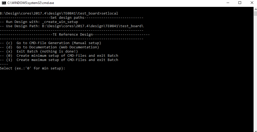
- Press 0 and enter for minimum setup
- (optional Win OS) Generate Virtual Drive or use short directory for the reference design (for example x:\<design name>)
- Create Project
- Select correct device and Xilinx install path on "design_basic_settings.cmd" and create Vivado project with "vivado_create_project_guimode.cmd"
Note: Select correct one, see TE Board Part Files
- Select correct device and Xilinx install path on "design_basic_settings.cmd" and create Vivado project with "vivado_create_project_guimode.cmd"
- Create HDF and export to prebuilt folder
- Run on Vivado TCL: TE::hw_build_design -export_prebuilt
Note: Script generate design and export files into \prebuilt\hardware\<short dir>. Use GUI is the same, except file export to prebuilt folder
- Run on Vivado TCL: TE::hw_build_design -export_prebuilt
- Generate MCS Firmware (optional):
- Create SDK Project with TE Scripts on Vivado TCL: TE::sw_run_sdk
- Create "SCU" application
Note: Select MCS Microblaze and SCU Application - Select Release Built
- Regenerate App
- (optional) Copy "\\workspace\sdk\scu\Release\scu.elf" into "\firmware\microblaze_mcs_0\"
- Regenerate Vivado Project or Update Bitfile only and "scu.elf"
- Copy MCS file with Bitfile into prebuilt folder
- Create SDK Project with TE Scripts on Vivado TCL: TE::sw_run_hsi
...
Xilinx documentation for programming and debugging: Vivado/SDK/SDSoC-Xilinx Software Programming and Debugging
QSPI
- Connect JTAG and power on PCB
- (if not done) Select correct device and Xilinx install path on "design_basic_settings.cmd" and create Vivado project with "vivado_create_project_guimode.cmd" or open with "vivado_open_project_guimode.cmd", if generated.
- Type on Vivado Console: TE::pr_program_flash_mcsfile -swapp
Note: Alternative use SDK or setup Flash on Vivado manually - Reboot (if not done automatically)
...
- Prepare HW like described on section Programming 70156396
- Connect UART USB (most cases same as JTAG)
- Power on PCB
Note: FPGA Loads Bitfile from Flash,MCS Firmware configure SI5338 and starts IBERT.
Do not reboot, if Bitfile programming over JTAG is used as programming method.- On TE0841 SI5338 has default configuration and reprogramming of SI5338 is optional
- LED:
- D1 (green) OFF→ MCS SI configuration finished (System Reset is off)
...
| Date | Document Revision | Authors | Description | ||||||||||||||||||||||
|---|---|---|---|---|---|---|---|---|---|---|---|---|---|---|---|---|---|---|---|---|---|---|---|---|---|
|
|
|
| ||||||||||||||||||||||
| v.5 | John Hartfiel |
| |||||||||||||||||||||||
| v.4 | John Hartfiel |
| |||||||||||||||||||||||
| 2018-04-16 | v.1 |
|
| ||||||||||||||||||||||
| All |
|
...
Overview
Content Tools