Page History
...
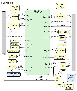
The Trenz Electronic TE0716 is a commercial-grade SoM (System on Module) based on Xilinx Zynq-7000 SoC XC7Z020, with 1GB of DDR3L-1600 SDRAM, 32MB of SPI flash memory, 10x 12-Bit Low Power SAR ADCs, 512Kb Serial EEPROM, Gigabit Ethernet PHY transceiver, a an USB PHY transceiver, a single chip USB 2.0 to UART/JTAG Interface (Xilinx License included), and powerful switching-mode power supplies for all on-board voltages.
...
| Scroll Title | ||||||||||||||||||||||||||||
|---|---|---|---|---|---|---|---|---|---|---|---|---|---|---|---|---|---|---|---|---|---|---|---|---|---|---|---|---|
| ||||||||||||||||||||||||||||
|
Main Components
...
| Scroll Title | ||||||||||||||||||||||||||||
|---|---|---|---|---|---|---|---|---|---|---|---|---|---|---|---|---|---|---|---|---|---|---|---|---|---|---|---|---|
| ||||||||||||||||||||||||||||
|
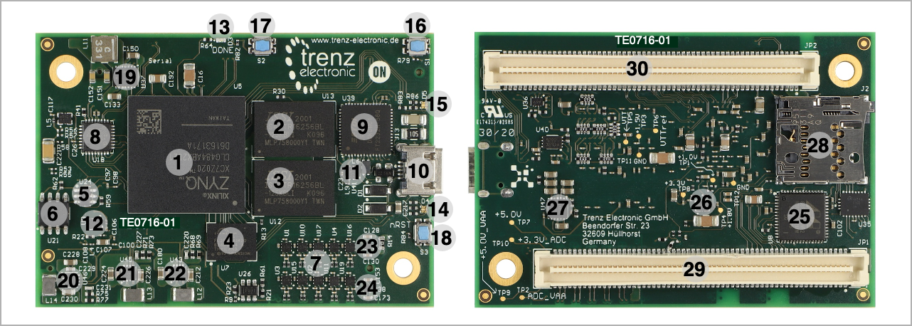
- Xilinx Zynq XC7Z SoC, U5 (Top)
- 4Gbit DDR3/L SDRAM, U13 (Top)
- 4Gbit DDR3/L SDRAM, U12 (Top)
- 32MByte Quad SPI Flash memory, U7 (Top)
- 2Kbit MAC address serial EEPROM with EUI-48TM node identity, U24 (Top)
- 512Kb Serial EEPROM memory, U21 (Top)
- 10x 12-Bit Low Power SAR ADCs, U1..U4, U10, U11, U15..U17, U19 (Top)
- High-speed USB 2.0 ULPI transceiver, U18 (Top)
- Single chip USB Interface 2.0 to UART / JTAG, U39 (Top)
- MicroUSB-B connector, J13 (Top)
- Low-power oscillator @ 12.000000MHz (OSCI-FTDI), U41 (Top)
- Low-power oscillator @ 25.000000MHz (ETH-CLK), U9 (Top)
- LED FPGA DONE (Green) 13 d3 (Top)
- User RGB LED 1 D4 (Top)
- User RGB LED 2 D5 (Top)
- Tactile Switch (User), S1 (Top)
- Tactile Switch (User), S2 (Top)
- Tactile Switch (Reset), S3 (Top)
- 5A Synchronous Buck DC-DC Converter (1V), U37 (Top)
- 2A Synchronous Buck DC-DC Converter (3.3V), U46 (Top)
- 2A Synchronous Buck DC-DC Converter (1.8V), U45 (Top)
- 2A Synchronous Buck DC-DC Converter (1.5V), U43 (Top)
- 250mA Ultra-Low Noise LDO Regulator (3.3V_ADC Digital I/O supply), U23 (Top)
- 250mA Ultra-Low Noise LDO Regulator (ADC_VAA Analog supply/reference, 3.3V), U38 (Top)
- Gigabit Ethernet PHY transceiver, U8 (Bottom)
- Low-power oscillator @ 33.333333MHz (PS-CLK), U6 (Bottom)
- 3A Sink/Source DDR Termination Regulator (VTT/VTTREF, 0.75V), U47 (Bottom)
- Card Connector microSD™, J2 (Bottom)
- 2x60 positions high speed/density plug connector, JP1 (Bottom)
- 2x60 positions high speed/density plug connector, JP2 (Bottom)
...
The TE0716 module has two 500MByte DDR3L SDRAM chips (U12 & U13) arranged into 32-bit wide memory bus providing total on-board memory size of 1GByte.
- Part number: IS43TR16256BL-125KBLI
- Configuration: 256Mx16.*
- Supply voltage: 1.35V (1.5V tolerant).
- Speed: 1.25ns @ CL11 (DDR3-1600)*
- Temperature: Industrial Range -40°C to +95°C Tcase.
Notes: * standard value but depends on assembly version.
Ethernet
| Scroll Title | |||||||||||||||||||||||
|---|---|---|---|---|---|---|---|---|---|---|---|---|---|---|---|---|---|---|---|---|---|---|---|
| |||||||||||||||||||||||
|
...
Clock Sources
| Scroll Title | ||||||||||||||||||||||||||
|---|---|---|---|---|---|---|---|---|---|---|---|---|---|---|---|---|---|---|---|---|---|---|---|---|---|---|
| ||||||||||||||||||||||||||
Bank
Schematic | U?? Pin | Notes | D-Tx | Driver Input | R-Rx | Reciever Output | |
...
| anchor | Table_OBP_CLK |
|---|---|
| title | Osillators |
...
Programmable Clock Generator
There is a programmable clock generator on-board (U??) provided in order to generate variable clocks for the module. Programming can be done using I2C via PIN header J??. The I2C Address is 0x??.
...
| anchor | Table_OBP_PCLK |
|---|---|
| title | Programmable Clock Generator Inputs and Outputs |
| Scroll Table Layout | ||||||||||||
|---|---|---|---|---|---|---|---|---|---|---|---|---|
|
...
IN0
...
XAXB
...
|
Power and PowerPower and Power-On Sequence
| Page properties | ||||
|---|---|---|---|---|
| ||||
In 'Power and Power-on Sequence' section there are three important digrams which must be drawn:
|
...
| Page properties | ||||||
|---|---|---|---|---|---|---|
| ||||||
|
? x ? modules use two or three Samtec Micro Tiger Eye Connector on TE0716 module use two 61083 BergStak® 0.8mm Plug Connectors on the bottom side.
- 3 x REF-??????? (compatible to ????????), (?? pins, ?? per row)
- Part Number: 61083-121402LF (compatible with 61082 Receptacle).
- Operating Temperature: -
??°C ~ ??°C- 40°C to +125°C.
- Current Rating:
??A per ContactNumber - 0.8A per Contact.
- Number of Positions:
??- 120 (60x per row)
- Number of Rows:
??- 2
Technical Specifications
Absolute Maximum Ratings
...
Physical Dimensions
Module size: ?? 45 mm × ?? 65 mm. Please download the assembly diagram for exact numbers.
Mating height with standard 61982 receptacle connectors: ? mm5mm, 7mm, 13mm and 17mm stack heights.
PCB thickness:
...
1.65 mm.
| Page properties | ||||
|---|---|---|---|---|
| ||||
In 'Physical Dimension' section, top and bottom view of module must be inserted, information regarding physical dimensions can be obtained through webpage for product in Shop.Trenz, (Download> Documents> Assembly part) for every SoM. For Example: for Module TE0728, Physical Dimension information can be captured by snipping tools from the link below:
|
...
Overview
Content Tools