Page History
...
The wiki page "Installation guide for Jupyter", available via the superior page, describes how to run Jupyter and , open a Notebook and execute it.
| Scroll Title | ||||||
|---|---|---|---|---|---|---|
| ||||||
|
...
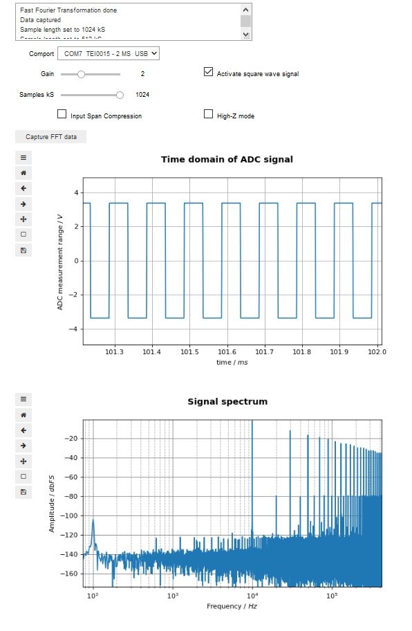
This demo is designed with the focus of capturing signals. Therefore the module works like a storage oscilloscope. After a For every trigger event, the module saves 1 million samples of ADC measurement in its SDRAM.
The demo scans for existing comports in its initialisation phase. So the module needs to be connected to the computer prior to running the demo.
In the Notebook, the user just selects which amount of the data are to be used for the evaluation.
Module and host pc setup
When this demo runs, it displays a graphical user interface, for setting up the comport, sample parameters, gain and module specific features. After selecting a COM-port, the demo and the module can communicate.. The following list describes the setup steps necessary prior to executing the Notebook:
- Open Jupyter and navigate to the Notebook.
- Apply a signal to the modules inputs:
Either via SMA- or via Pin Header- connection,
it is sufficient to use only one of the differential inputs,
but for the best results, apply the signal via both differential inputs
(Connection diagrams are in the next chapter) - Connect the module to the host pc
- Place the mouse cursor into the Notebooks cell via left click
- Run the Note by pressing the Run button
(The demo scans for existing comports in its initialisation phase. So the module needs to be connected to the computer prior to running the demo) - Enjoy playing

Connecting the input signal
| Scroll Title | ||||||
|---|---|---|---|---|---|---|
| ||||||
|
...
| Scroll Title | ||||||||
|---|---|---|---|---|---|---|---|---|
|
| Scroll Ignore |
|---|
|
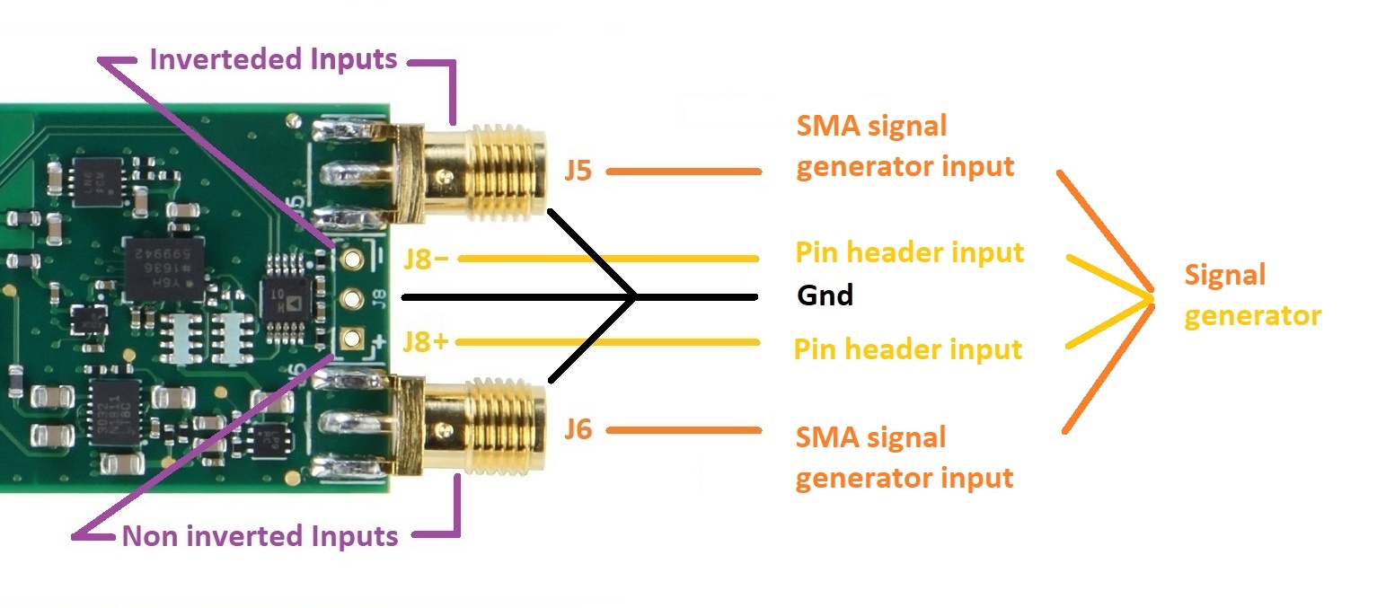
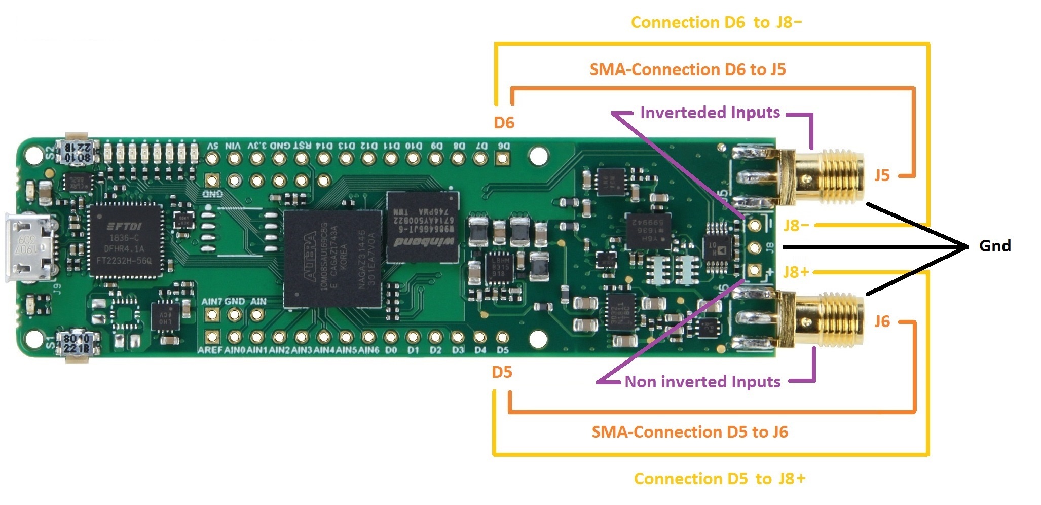
The module offers a Non inverted input and an inverted input. The inputs are accessible through either a SMA connection or a breakout connection.
Inverted inputs are J5 and -J8
Non inverted inputs are J6 and +J8
...
|
...
An other option is to use the modules square wave signal output. Connect the digital outputs D5 and D6 to the inputs as you like and activate the signal through the checkbox. Be careful, do not shorten the outputs D5 or D6 to ground.
...
|
General interface / communication description
...
Overview
Content Tools