Page History
| Page properties | ||||||||||||||||||||||||||||
|---|---|---|---|---|---|---|---|---|---|---|---|---|---|---|---|---|---|---|---|---|---|---|---|---|---|---|---|---|
| ||||||||||||||||||||||||||||
Design Name always "TE Series Name" + Design name, for example "TEI0006 Test Board"
|
| Custom_table_size_100 |
|---|
| Page properties | ||||||||||||||||||||||||||||||||||||||||
|---|---|---|---|---|---|---|---|---|---|---|---|---|---|---|---|---|---|---|---|---|---|---|---|---|---|---|---|---|---|---|---|---|---|---|---|---|---|---|---|---|
| ||||||||||||||||||||||||||||||||||||||||
Important General Note:
|
Overview
| Scroll Ignore | ||||||||||||||
|---|---|---|---|---|---|---|---|---|---|---|---|---|---|---|
| ||||||||||||||
| Page properties | ||||
|---|---|---|---|---|
| ||||
Notes :
|
Refer to http://trenz.org/tei0022-info for the current online version of this manual and other available documentation.
Key Features
| Page properties | ||||
|---|---|---|---|---|
| ||||
Notes :
|
| Excerpt |
|---|
|
Revision History
| Page properties | ||||
|---|---|---|---|---|
| ||||
Notes:
|
| Scroll Title | ||||||||||||||||||||||||||||||||||||||
|---|---|---|---|---|---|---|---|---|---|---|---|---|---|---|---|---|---|---|---|---|---|---|---|---|---|---|---|---|---|---|---|---|---|---|---|---|---|---|
| ||||||||||||||||||||||||||||||||||||||
|
Release Notes and Know Issues
| Page properties | ||||
|---|---|---|---|---|
| ||||
Notes:
|
| Scroll Title | ||||||||||||||||||||||||||
|---|---|---|---|---|---|---|---|---|---|---|---|---|---|---|---|---|---|---|---|---|---|---|---|---|---|---|
| ||||||||||||||||||||||||||
|
Requirements
Software
| Page properties | ||||
|---|---|---|---|---|
| ||||
Notes :
|
| Scroll Title | ||||||||||||||||||||||||||
|---|---|---|---|---|---|---|---|---|---|---|---|---|---|---|---|---|---|---|---|---|---|---|---|---|---|---|
| ||||||||||||||||||||||||||
|
Hardware
| Page properties | ||||
|---|---|---|---|---|
| ||||
Notes :
|
Complete List is available on <project folder>/board_files/*_board_files.csv
Design supports following modules:
| Scroll Title | ||||||||||||||||||||||||||||||||||||
|---|---|---|---|---|---|---|---|---|---|---|---|---|---|---|---|---|---|---|---|---|---|---|---|---|---|---|---|---|---|---|---|---|---|---|---|---|
| ||||||||||||||||||||||||||||||||||||
*used as reference |
Design supports following carriers:
| Scroll Title | ||||||||||||||||||||||
|---|---|---|---|---|---|---|---|---|---|---|---|---|---|---|---|---|---|---|---|---|---|---|
| ||||||||||||||||||||||
*used as reference |
Additional HW Requirements:
| Scroll Title | ||||||||||||||||||||||||||||||||
|---|---|---|---|---|---|---|---|---|---|---|---|---|---|---|---|---|---|---|---|---|---|---|---|---|---|---|---|---|---|---|---|---|
| ||||||||||||||||||||||||||||||||
*used as reference |
Content
| Page properties | ||||
|---|---|---|---|---|
| ||||
Notes :
|
For general structure and usage of the reference design, see Project Delivery - Intel devices
Design Sources
| Scroll Title | ||||||||||||||||||||||||||||
|---|---|---|---|---|---|---|---|---|---|---|---|---|---|---|---|---|---|---|---|---|---|---|---|---|---|---|---|---|
| ||||||||||||||||||||||||||||
|
Prebuilt
| Page properties | ||||||||||||||||||||||||||||||||||||||||||||||||||||||||||||||||||
|---|---|---|---|---|---|---|---|---|---|---|---|---|---|---|---|---|---|---|---|---|---|---|---|---|---|---|---|---|---|---|---|---|---|---|---|---|---|---|---|---|---|---|---|---|---|---|---|---|---|---|---|---|---|---|---|---|---|---|---|---|---|---|---|---|---|---|
| ||||||||||||||||||||||||||||||||||||||||||||||||||||||||||||||||||
Notes :
|
| Scroll Title | ||||||||||||||||||||||||||||||||||||
|---|---|---|---|---|---|---|---|---|---|---|---|---|---|---|---|---|---|---|---|---|---|---|---|---|---|---|---|---|---|---|---|---|---|---|---|---|
| ||||||||||||||||||||||||||||||||||||
| ||||||||||||||||||||||||||||||||||||
| Scroll Title | ||||||||||||||||||||||||||||||||||||
| ||||||||||||||||||||||||||||||||||||
|
Download
|
Download
Reference Design is only usable with the specified Quartus versionReference Design is only usable with the specified Quartus version. Do never use different versions of Quartus software for the same project.
| Page properties | ||||
|---|---|---|---|---|
| ||||
|
Reference Design is available on:
Design Flow
| Scroll Ignore | ||||||||||||||
|---|---|---|---|---|---|---|---|---|---|---|---|---|---|---|
| ||||||||||||||
| Page properties | ||||
|---|---|---|---|---|
| ||||
Notes :
|
| Note |
|---|
Reference Design is available with and without prebuilt files. It's recommended to use TE prebuilt files for first launch. |
Trenz Electronic provides a tcl based built environment based on Quartus Design Flow.
See also:
The Trenz Electronic FPGA Reference Designs are TCL-script based projects. To create a project, open a project or program a device execute "create_project_win.cmd" on Windows OS and "create_project_linux.sh" on Linux OS.
TE Scripts are only needed to generate the quartus project, all other additional steps are optional and can also executed by Intel Quartus/SDK GUI. For currently Scripts limitations on Win OS and Linux OS see: Project Delivery - Intel devices → Currently limitations of functionality
- Open create_project_win.cmd/create_project_linux.sh:
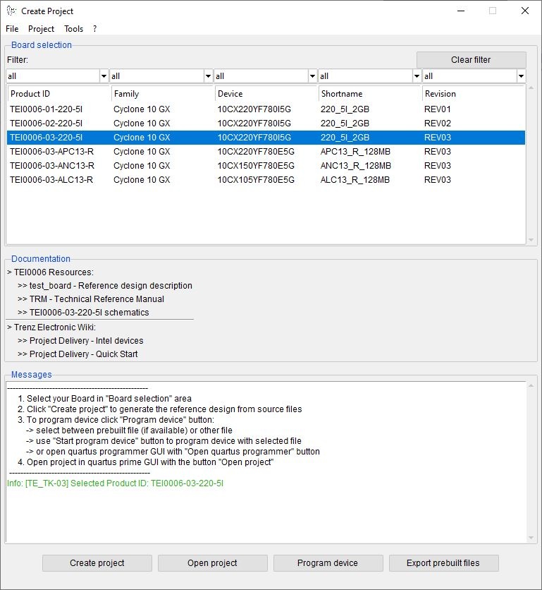
- Select Board in "Board selection"
- Click on "Create project" button to create project
- (optional for manual changes) Select correct quartus installation path in "<project folder>/settings/design_basic_settings.tcl"
- Create and configure your Yocto Linux project, see Yocto KICKstart
- Copy the generated meta-<module> folder from <project name>/os/yocto/meta-<module> to the path/to/yocto/poky/ directory
- Follow the steps from Yocto KICKstart#Create a project for an Intel FPGA device without running the 'bitbake' command
Add the generated bsp layer meta-<machine> to path/to/yocto/poky/build/conf/bblayers.conf with:
Code Block theme Midnight linenumbers true bitbake-layers add-layer ../meta-tei0022
Info Note: The generated meta-tei0022 layer depends on the meta-altera layer (for more information see: Yocto KICKstart#Used source files), so you need to add both bsp layers to bblayers.conf
Redefine the variable MACHINE with 'tei0022-<Board-Part-Short-Name>' in path/to/yocto/poky/build/conf/local.conf. The correct MACHINE name can be found in the #Hardware table.
Also define the variables INITRAMFS_IMAGE_BUNDLE and INITRAMFS_IMAGE to create a ram disk image.Code Block theme Midnight linenumbers true sed -i '/^MACHINE/s/MACHINE/#MACHINE/g' conf/local.conf echo -e '\nMACHINE = "tei0022-<Board-Part-Short-Name>"' >> conf/local.conf echo -e '\nINITRAMFS_IMAGE_BUNDLE = "1"' >> conf/local.conf echo -e 'INITRAMFS_IMAGE = "te-initramfs"' >> conf/local.confBuild the image with following command (the image recipes are located in meta-tei0022/recipes-core/imagesBuild the image with following command (the image recipes are located in meta-tei0022/recipes-images/yocto/):
Code Block theme Midnight linenumbers true bitbake tei0022te-image-minimal
- [optional] Create a debian or ubuntu rootfs with/without desktop environment for this board. For more information and instructions see: Create debian/ubuntu rootfs - Intel devices
Launch
| Scroll Ignore |
|---|
| Page properties | ||||
|---|---|---|---|---|
| ||||
Note:
|
Programming
| Note |
|---|
Check Module and Carrier TRMs for proper HW configuration before you try any design. |
SD-Boot mode
- Follow the steps described in Reference Designs with Yocto - Intel devices to copy the generated linux image to the SD card.
- Set Boot Mode to SD-Boot.
- see module TRM for correct settings
- Insert SD-Card in SD-Slot.
QSPI
Not used on this example.
JTAG
Not used on this example.
Usage
- Prepare HW like described on section #Programming
- Connect UART USB (most cases same as JTAG)
- Power on PCB
UART
Get prebuilt boot binaries
| Note |
|---|
Reference Design is also available with prebuilt files. It's recommended to use TE prebuilt files for first launch. |
- Run create_project_win.cmd/create_project_linux.sh
- Select Module in 'Board selection'
- Click on 'Export prebuilt files' button
- Folder <project folder>/_binaries_<Article Name> with subfolder boot_linux will be generated and opened
QSPI-Boot mode
Option for u-boot-with-spl.sfp on QSPI flash and zimage-initramfs-<Yocto Machine Name>.bin, <Yocto Machine Name>.dtb, soc_system.rbf and extlinux/extlinux.conf on SD card
Use files from "<project folder>\_binaries_<Article Name>\boot_linux" from generated binary folder,see: #Get prebuilt boot binaries
- Set JTAGSEL0 and JTAGSEL1 to Cyclone V HPS access
- see TEI0022 TRM#Micro USB Connector (JTAG) for correct settings
- ConnectJTAG (USB connector J13) and power on carrier with module
- Open path/to/intelFPGA_lite/21.1/embedded/Embedded_Command_Shell.bat ( Win OS)/path/to/intelFPGA_lite/21.1/embedded/embedded_command_shell.sh (Linux OS) from Intel SoC FPGA EDS
Run following commands:
Open Serial Console (e.g. PuTTY)- Speed: 115200
- Press reset button
- Linux Console:
Login data:
Info Note: Wait until Linux boot finished
Code Block theme Midnight linenumbers true Username: root Password: rootYou can use Linux shell now.
i2cdetectCode Block theme Midnight linenumbers true
y -rquartus_hps -
(checkc 1 -o pv
I2C 1 Bus) udhcpc (ETH0 check) lsusb (USB check)-a
select COM Port
| Info |
|---|
Win OS: see device manager Linux OS: see dmesg | grep tty (UART is *USB1) |
Monitor
0x0 path/to/_binaries_<Article Name>/boot_linux/u-boot-with-spl.sfp- Copy zimage-initramfs-<Yocto Machine Name>.bin, <Yocto Machine Name>.dtb, soc_system.rbf and the extlinux folder from path/to/_binaries_<Article Name>/boot_linux/ to SD card
- Set Boot Mode to QSPI-Boot and insert the SD card in the SD-Slot
- see TEI0022 TRM#Configuration Signals for correct settings
SD-Boot mode
- Prepare SD card as follows for SD-Boot
Run following command to get the device name of the SD card (e.g. /dev/sdx):
Code Block theme Midnight linenumbers true lsblk- Insert SD card in the SD card reader, unmount and erase it
- Connect the Monitor to HDMI
- Connect the Mouse+Keyboard to USB
- Press reset button
- If yocto default rootfs is used, the linux console is displayed:
Login data:
Info Note: Wait until Linux boot finished
Code Block theme Midnight linenumbers true Username: root Password: rootYou can use Linux shell now.
Code Block theme Midnight linenumbers true i2cdetectsudo -y -r 1 (check I2C 1 Bus) udhcpc (ETH0 check) lsusb (USB check)
- [optional] Ubuntu/Debian desktop will be started automatically (for more information see #Rootfs)
System Design - Quartus
| Page properties | ||||
|---|---|---|---|---|
| ||||
Note:
|
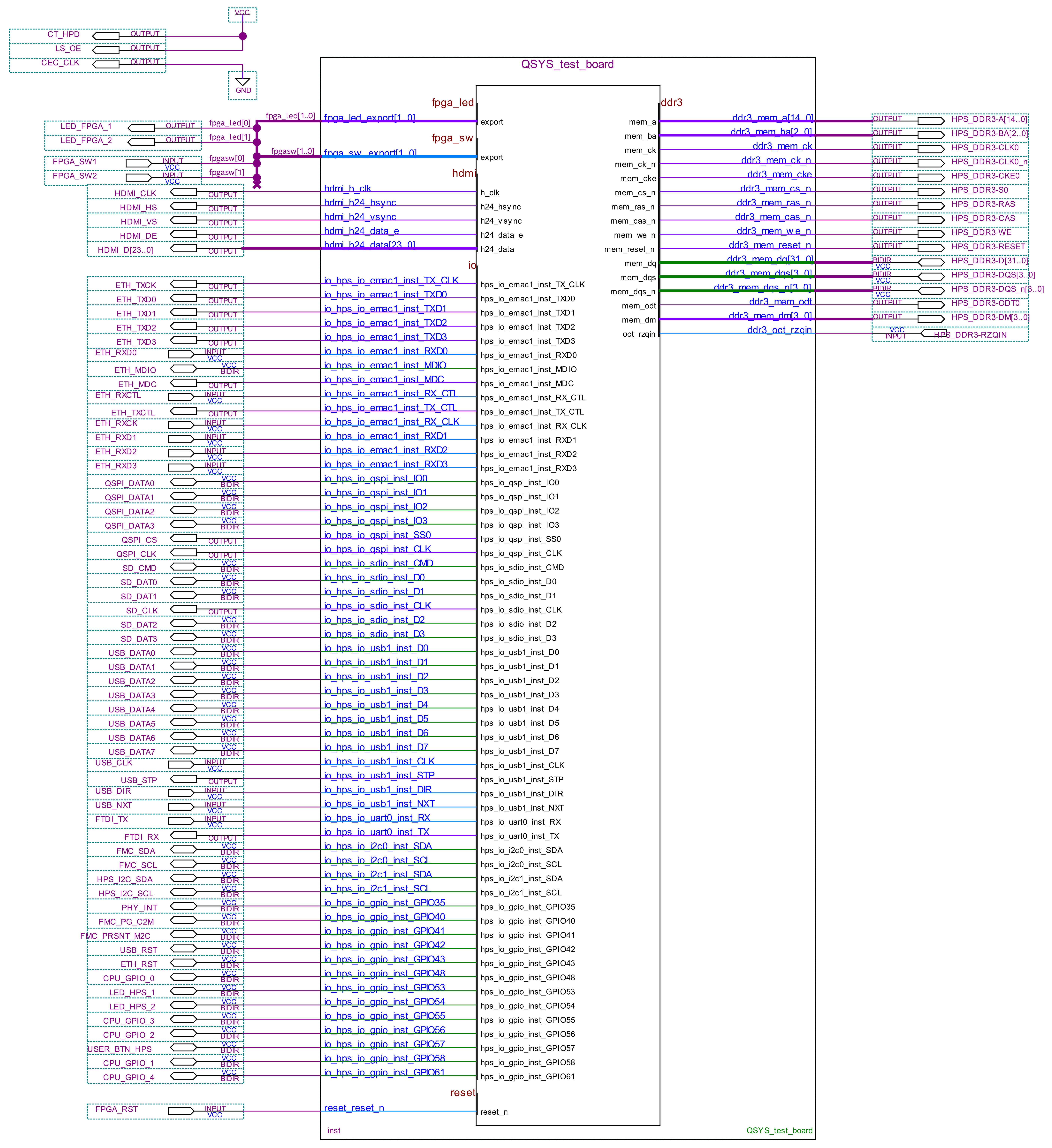
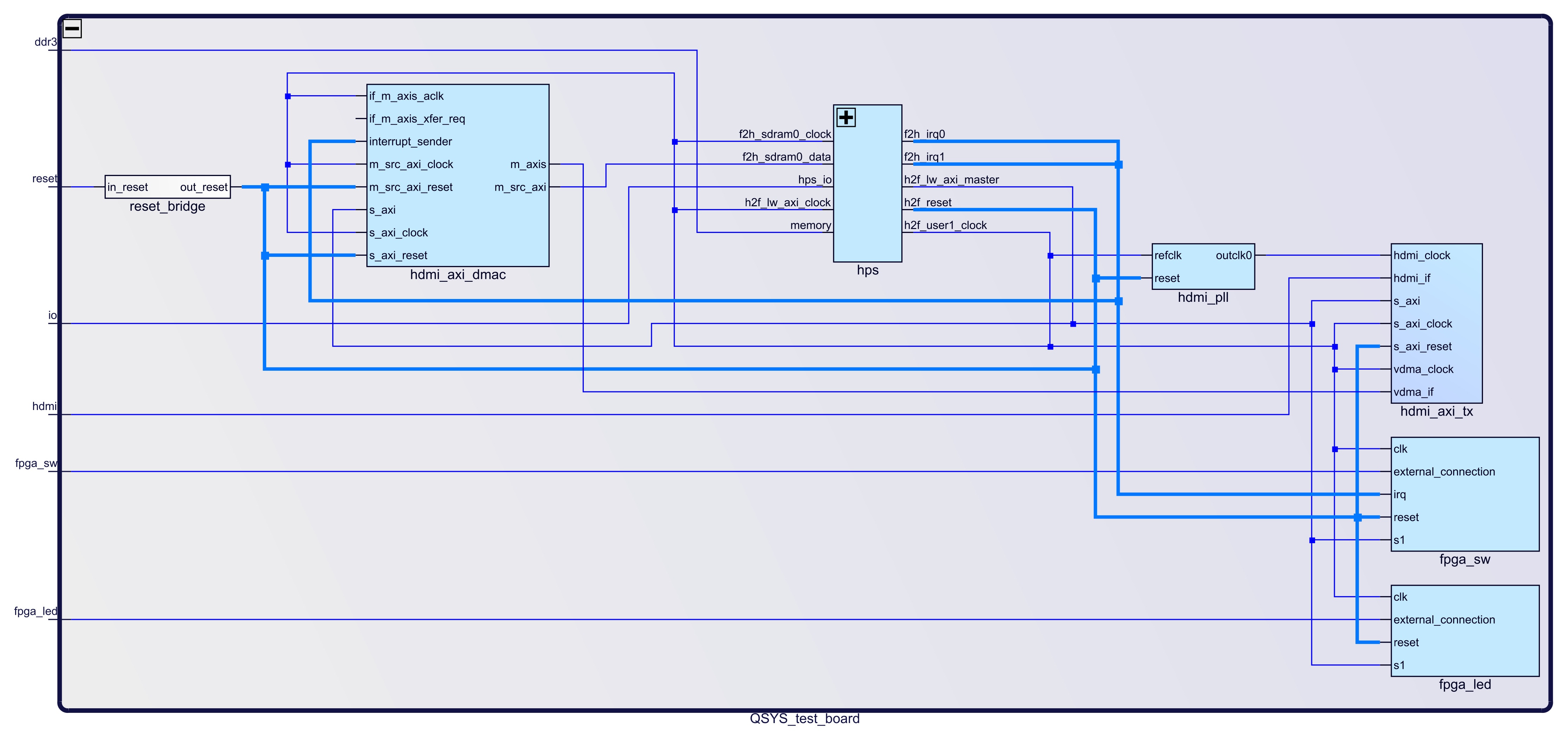
Block Design
The block designs may differ depending on the assembly variant.
| Scroll Title | ||||||
|---|---|---|---|---|---|---|
| ||||||
 |
| Scroll Title | ||||||
|---|---|---|---|---|---|---|
| ||||||
HPS Interfaces
Activated interfaces:
umount /dev/sdx
sudo sfdisk --delete /dev/sdx
Create required partitions on the SD card (partition 1: 50MB, FAT32 / partition 2: 2MB, a2)
Code Block theme Midnight linenumbers true echo -e ',50M,c\n,2M,a2' | sudo sfdisk /dev/sdb --force sudo mkfs.vfat -F 32 -n boot /dev/sdb1Copy the u-boot file to partition 2 of the SD card
Code Block theme Midnight linenumbers true sudo dd if=path/to/_binaries_<Article Name>/boot_linux/u-boot-with-spl.sfp of=/dev/sdb2 bs=1M seek=0 sync- Copy zimage-initramfs-<Yocto Machine Name>.bin, <Yocto Machine Name>.dtb, soc_system.rbf and the extlinux folder from path/to/_binaries_<Article Name>/boot_linux/ via file manager to the partition 1 (named 'boot') on SD card.
- Set Boot Mode to SD-Boot.
- see TEI0022 TRM#Configuration Signals for correct settings
- Insert SD-Card in the SD-Slot.
JTAG
Not used on this example.
Usage
- Prepare HW like described on section #Programming
- Connect UART USB (USB connector J5)
- Connect your board to the network
- Power on PCB
UART
- Open Serial Console (e.g. PuTTY)
select COM Port
Info Win OS: see device manager
Linux OS: see dmesg | grep tty (UART is *USB1)
- Speed: 115200
- Press reset button
- Linux Console:
Login data:
Info Note: Wait until Linux boot finished
Code Block theme Midnight linenumbers true Username: root Password: rootYou can use Linux shell now.
Code Block theme Midnight linenumbers true #check I2C 1 Bus i2cdetect -y -r 1 #ETH0 check udhcpc #USB check lsusb #toggle leds (state= 0 or 1 / led_name= hps_led1, hps_led2, fpga_led1, fpga_led2) echo <state> > /sys/class/leds/<led_name>/brightness #check temperature (Unit: millidegree Celsius) cat /sys/class/hwmon/hwmon0/device/temp1_input
Monitor
- Connect the Monitor to HDMI
- Connect the Mouse+Keyboard to USB
- Press reset button
- The linux console is displayed:
Login data:
Info Note: Wait until Linux boot finished
Code Block theme Midnight linenumbers true Username: root Password: rootYou can use Linux shell now.
Code Block theme Midnight linenumbers true #check I2C 1 Bus i2cdetect -y -r 1 #ETH0 check udhcpc #USB check lsusb #toggle leds (state= 0 or 1 / led_name= hps_led1, hps_led2, fpga_led1, fpga_led2) echo <state> > /sys/class/leds/<led_name>/brightness #check temperature (Unit: millidegree Celsius) cat /sys/class/hwmon/hwmon0/device/temp1_input
- [optional] Ubuntu/Debian desktop will be started automatically (for more information see #Rootfs)
System Design - Quartus
| Scroll Ignore |
|---|
| Page properties | ||||
|---|---|---|---|---|
| ||||
Note:
|
Block Design
The block designs may differ depending on the assembly variant.
| Scroll Title | ||||||
|---|---|---|---|---|---|---|
| ||||||
|
| Scroll Title | ||||||
|---|---|---|---|---|---|---|
| ||||||
 |
HPS Interfaces
Activated interfaces:
| Type | Note |
| DDR | -- |
| EMAC1 | -- |
| QSPI | -- |
| SDMMC | -- |
| USB1 | -- |
| UART0 | -- |
| I2C0 | -- |
| I2C1 | -- |
| GPIO35 | connected to ETH PHY_INT pin |
| GPIO42 | connected to USB_RST pin |
| GPIO43 | connected to ETH_RST pin |
| GPIO48 | connected to CPU_GPIO_0 pin |
| GPIO53 | connected to LED_HPS_1 pin |
| GPIO54 | connected to LED_HPS_2 pin |
| GPIO55 | connected to CPU_GPIO_3 pin |
| GPIO56 | connected to CPU_GPIO_2 pin |
| GPIO57 | connected to USER_BTN_HPS pin |
| GPIO58 | connected to CPU_GPIO_1 pin |
| GPIO61 | connected to CPU_GPIO_4 pin |
Software Design - Yocto
| Scroll Ignore |
|---|
For Yocto installation and project creation, follow instructions from:
- Yocto KICKstart
- Create a custom BSP layer for Intel SoC or FPGA
- Create debian/ubuntu rootfs - Intel devices
U-Boot
Start with Create a custom BSP layer for Intel SoC or FPGA#Configure u-boot
File location: meta-tei0022/recipes-bsp/u-boot/
Changes:
select tei0022 board
# CONFIG_TARGET_SOCFPGA_CYCLONE5_SOCDK is not set
CONFIG_TARGET_TEI0022=y
configure bootcommand (load soc_system.rbf file into the FPGA
CONFIG_BOOTCOMMAND="load mmc 0:1 $loadaddr soc_system.rbf; fpga load 0 $loadaddr $filesize; bridge enable; run distro_bootcmd"
- enable misc_init_r function (need to call TE_read_eeprom_mac function)
CONFIG_MISC_INIT_R=y
CONFIG_MISC=y
MAC from eeprom together with uboot:
CONFIG_I2C_EEPROM=y
CONFIG_SYS_I2C_EEPROM_ADDR=0x50
CONFIG_SYS_I2C_EEPROM_BUS=1
CONFIG_SYS_EEPROM_SIZE=256
CONFIG_SYS_EEPROM_PAGE_WRITE_BITS=0
CONFIG_SYS_EEPROM_PAGE_WRITE_DELAY_MS=0
CONFIG_SYS_I2C_EEPROM_ADDR_LEN=1
CONFIG_SYS_I2C_EEPROM_ADDR_OVERFLOW=0
configure eth
- CONFIG_PHYLIB=y
CONFIG_NETDEVICES=y
CONFIG_RGMII=y
# CONFIG_MII is not set
- select device tree
- CONFIG_DEFAULT_DEVICE_TREE="tei0022_<Board Part Short Name>"
- CONFIG_DEFAULT_FDT_FILE="tei0022_<Board Part Short Name>.dtb"
Device Tree
U-boot Device Tree
| Code Block | ||||
|---|---|---|---|---|
| ||||
#include "socfpga_cyclone5.dtsi"

/ {
	model = "Trenz Electronic - TEI0022";
	compatible = "altr,socfpga-cyclone5", "altr,socfpga";

	chosen {
		bootargs = "earlyprintk";
		stdout-path = "serial0:115200n8";
	};

	memory {
		name = "memory";
		device_type = "memory";
		reg = <0x0 0x40000000>;
	};

	aliases {
		ethernet0 = &gmac1;
	};
};

&gpio0 {
	status = "okay";
};

&gpio1 {
	status = "okay";
};

&gpio2 {
	status = "okay";
};

&gmac1 {
	#address-cells = <1>;
	#size-cells = <0>;

	status = "okay";
	phy-mode = "rgmii";

	ethernet-phy@1 {
		reg = <1>;
		adi,rx-internal-delay-ps = <2000>;
		adi,tx-internal-delay-ps = <2000>;
	};
};

&i2c1 {
	status = "okay";
	clock-frequency = <100000>;
	eeprom: eeprom@50 {
		compatible = "microchip,24aa02e48","atmel,24c02";
		reg = <0x50>;
	};
};

&uart0 {
	clock-frequency = <100000000>;
};

&mmc0 {
	status = "okay";
};

&qspi {
	status = "okay";

	flash: mt25ql256a@0 {
		#address-cells = <1>;
		#size-cells = <1>;
		compatible = "jedec,spi-nor";
		reg = <0>;
		spi-max-frequency = <100000000>;
		m25p,fast-read;

		cdns,page-size = <256>;
		cdns,block-size = <16>;
		cdns,read-delay = <4>;
		cdns,tshsl-ns = <50>;
		cdns,tsd2d-ns = <50>;
		cdns,tchsh-ns = <4>;
		cdns,tslch-ns = <4>;

		partition@qspi-boot {
			label = "Flash 0 Raw Data";
reg = <0x0 0x400000> |
Software Design - Yocto
For Yocto installation and project creation, follow instructions from:
- Yocto KICKstart
- Create a custom BSP layer for Intel SoC or FPGA
- Create debian/ubuntu rootfs - Intel devices
U-Boot
Start with Create a custom BSP layer for Intel SoC or FPGA#Configure u-boot
File location: meta-tei0022/recipes-bsp/u-boot/
Changes:
select tei0022 board
# CONFIG_TARGET_SOCFPGA_CYCLONE5_SOCDK is not set
CONFIG_TARGET_TEI0022=y
configure bootcommand (load soc_system.rbf file into the FPGA
CONFIG_BOOTCOMMAND="load mmc 0:1 $loadaddr soc_system.rbf; fpga load 0 $loadaddr $filesize; bridge enable; run distro_bootcmd"
- enable misc_init_r function (need to call TE_read_eeprom_mac function)
CONFIG_MISC_INIT_R=y
CONFIG_MISC=y
MAC from eeprom together with uboot:
CONFIG_I2C_EEPROM=y
CONFIG_SYS_I2C_EEPROM_ADDR=0x50
CONFIG_SYS_I2C_EEPROM_BUS=1
CONFIG_SYS_EEPROM_SIZE=256
CONFIG_SYS_EEPROM_PAGE_WRITE_BITS=0
CONFIG_SYS_EEPROM_PAGE_WRITE_DELAY_MS=0
CONFIG_SYS_I2C_EEPROM_ADDR_LEN=1
CONFIG_SYS_I2C_EEPROM_ADDR_OVERFLOW=0
configure eth
- CONFIG_PHYLIB=y
CONFIG_NETDEVICES=y
CONFIG_RGMII=y
# CONFIG_MII is not set
- select device tree
- CONFIG_DEFAULT_DEVICE_TREE="tei0022_<Board Part Short Name>"
- CONFIG_DEFAULT_FDT_FILE="tei0022_<Board Part Short Name>.dtb"
Device Tree
| Code Block | ||||
|---|---|---|---|---|
| ||||
#include "socfpga_cyclone5.dtsi" #include "dt-bindings/interrupt-controller/irq.h" #include <dt-bindings/gpio/gpio.h> / { chosen { bootargs = "earlyprintk"; stdout-path = "serial0:115200n8"; }; axi_dma_clk: axi_dma_clk { #clock-cells = <0x0>; compatible = "fixed-clock"; clock-frequency = <100000000>; clock-output-names = "axi_dma_clock"; }; sys_clk: sys_clk { #clock-cells = <0x0>; compatible = "fixed-clock"; clock-frequency = <80000000>; clock-output-names = "sys_clock"; }; hdmi_pll: hdmi_pll { compatible = "altr,altera_iopll-18.1"; #clock-cells = <1>; hdmi_pll_outclk0: hdmi_pll_outclk0 { compatible = "fixed-clock"; #clock-cells = <0>; clock-frequency = <148500000>; clock-output-names = "hdmi_pll-outclk0"; }; }; vdd: regulator-vdd { compatible = "regulator-fixed"; regulator-name = "fixed-supply"; regulator-min-microvolt = <1800000>; regulator-max-microvolt = <1800000>; regulator-always-on; }; vdd_3_3: regulator-vdd { compatible = "regulator-fixed"; regulator-name = "fixed-supply"; regulator-min-microvolt = <3300000>; regulator-max-microvolt = <3300000>; regulator-always-on; }; vref: regulator-vref { compatible = "regulator-fixed"; regulator-name = "fixed-supply"; regulator-min-microvolt = <2500000>; regulator-max-microvolt = <2500000>; regulator-always-on; }; soc { i2c1: i2c@ffc05000 { status = "okay"; speed-mode = <0>; #address-cells = <1>; #size-cells = <0>; adv7511: adv7511@39 { compatible = "adi,adv7511"; reg = <0x39>, <0x3f>; reg-names = "primary", "edid"; adi,input-depth = <8>; adi,input-colorspace = "yuv422"; adi,input-clock = "1x"; adi,input-style = <1>; adi,input-justification = "right"; adi,clock-delay = <(0)>; avdd-supply = <&vdd>; dvdd-supply = <&vdd>; pvdd-supply = <&vdd>; dvdd-3v-supply = <&vdd_3_3>; bgvdd-supply = <&vdd>; status = "okay"; ports { #address-cells = <1>; #size-cells = <0>; port@0 { reg = <0>; adv7511_in: endpoint { remote-endpoint = <&axi_hdmi_out>; }; }; port@1 { reg = <1>; }; }; }; }; sys_hps_bridges: bridge@ff200000 { compatible = "simple-bus"; reg = <0xff200000 0x00200000>; reg-names = "axi_h2f_lw"; #address-cells = <2>; #size-cells = <1>; ranges = <0x00000001 0x00001000 0xff201000 0x00000010>, <0x00000001 0x00001010 0xff201010 0x00000010>, <0x00000001 0x00001020 0xff201020 0x00000008>, <0x00000001 0x00001030 0xff201030 0x00000008>, <0x00000001 0x00010000 0xff210000 0x00000800>, <0x00000001 0x00020000 0xff220000 0x00010000>; jtag_uart: jtag-uart@100001030 { compatible = "altr,juart-1.0"; reg = <0x00000001 0x000001030 0x00000008>; interrupts = <0 40 4>; }; sysid: sysid@100001020 { compatible = "altr,sysid-1.0"; reg = <0x00000001 0x00001020 0x00000008>; }; fpga_sw: fpga-sw@100001000 { compatible = "altr,pio-1.0"; reg = <0x00000001 0x00001000 0x00000010>; interrupts = <0 41 1>; altr,gpio-bank-width = <2>; #gpio-cells = <2>; gpio-controller; interrupt-cells = <1>; interrupt-controller; altr,interrupt-type = <IRQ_TYPE_EDGE_BOTH>; }; fpga_led: fpga-led@100001010 { compatible = "altr,pio-1.0"; reg = <0x00000001 0x00001010 0x00000010>; altr,gpio-bank-width = <2>; #gpio-cells = <2>; gpio-controller; }; leds { compatible = "gpio-leds"; fpgaled0 { label = "fpga_led0"; gpios = <&fpga_led 0 1>; }; fpgaled1 { label = "fpga_led1"; gpios = <&fpga_led 1 1>; }; }; hdmi_axi_dmac: axi-dmac@100010000 { compatible = "adi,axi-dmac-1.00.a"; reg = <0x00000001 0x00010000 0x00000800>; #dma-cells = <1>; interrupt-parent = <&intc>; interrupts = <0 42 4>; clocks = <&axi_dma_clk 0>; status = "okay"; adi,channels { #size-cells = <0>; #address-cells = <1>; dma-channel@0 { reg = <0>; adi,source-bus-width = <64>; adi,source-bus-type = <0>; adi,destination-bus-width = <64>; adi,destination-bus-type = <1>; }; }; }; hdmi_axi_tx: axi-hdmi-tx@100020000 { compatible = "adi,axi-hdmi-tx-1.00.a"; reg = <0x00000001 0x00020000 0x10000>; dmas = <&hdmi_axi_dmac 0>; dma-names = "video"; clocks = <&hdmi_pll_outclk0 0>; status = "okay"; port { axi_hdmi_out: endpoint { remote-endpoint = <&adv7511_in>; }; }; }; }; }; }; &gmac1 { #address-cells = <1>; #size-cells = <0>; }; |
| Code Block | ||||
|---|---|---|---|---|
| ||||
#include "socfpga-common-u-boot.dtsi" &watchdog0 { status = "okaydisabled"; phy-mode = "rgmii"}; ethernet-phy@1&mmc { reg = <1>; adi,rx-internal-delay-ps = <2000>; adi,tx-internal-delay-ps = <2000>; }u-boot,dm-pre-reloc; }; &i2c1qspi { status = "okay"; clock-frequency = <100000>; eeprom: eeprom@50 { u-boot,dm-pre-reloc; }; &flash { compatible = "atmeljedec,24c08spi-nor"; reg = <0x50>u-boot,dm-pre-reloc; }; }; partition@qspi-boot { label = "Flash 0 Raw Data"; reg = <0x0 0x400000>; }; }; &uart0 { clock-frequency = <100000000>; u-boot,dm-pre-reloc; }; &porta { bank-name = "porta"; }; &portb { bank-name = "portb"; }; &portc { bank-name = "portc"; }; |
Kernel Device Tree
| Code Block | ||||
|---|---|---|---|---|
| ||||
#include "socfpga_cyclone5.dtsi"

/ {
	model = "Trenz Electronic - TEI0022";
	compatible = "altr,socfpga-cyclone5", "altr,socfpga";

	chosen {
		bootargs = "earlyprintk";
		stdout-path = "serial0:115200n8";
	};

	memory {
		name = "memory";
		device_type = "memory";
		reg = <0x0 0x40000000>;
	};

	aliases {
		ethernet0 = &gmac1;
	};

	regulator_1_8v: 1-8-v-regulator {
| ||||
| Code Block | ||||
| ||||
#include "socfpga_cyclone5.dtsi" #include "dt-bindings/interrupt-controller/irq.h" #include <dt-bindings/gpio/gpio.h> / { chosen { bootargs = "earlyprintk"; stdout-path = "serial0:115200n8"; }; axi_dma_clk: axi_dma_clk { #clock-cells = <0x0>; compatible = "fixed-clock"; clock-frequency = <100000000>; clock-output-names = "axi_dma_clock"; }; sys_clk: sys_clk { #clock-cells = <0x0>; compatible = "fixed-clock"; clock-frequency = <80000000>; clock-output-names = "sys_clock"; }; hdmi_pll: hdmi_pll { compatible = "altr,altera_iopll-18.1"; #clock-cells = <1>; hdmi_pll_outclk0: hdmi_pll_outclk0 { compatible = "fixed-clock"; #clock-cells = <0>; clock-frequency = <148500000>; clock-output-names = "hdmi_pll-outclk0"; }; }; vdd: regulator-vdd { compatible = "regulator-fixed"; regulator-name = "fixed-supply"; regulator-name = "1.8V"; regulator-min-microvolt = <1800000>; regulator-max-microvolt = <1800000>; regulator-always-on; }; vdd regulator_3_33v: regulator-vdd3-3-v-regulator { compatible = "regulator-fixed"; regulator-name = "fixed-supply3.3V"; regulator-min-microvolt = <3300000>; regulator-max-microvolt = <3300000>; regulator-always-on; }; vref: regulator-vref { hdmi_pll: hdmi_pll { compatible = "regulator-fixed"; regulator-name = "fixed-supply"; regulator-min-microvolt = <2500000>; regulator-max-microvolt = <2500000>; regulator-always-on; }; soc { i2c1: i2c@ffc05000 { status = "okay"; speed-mode = <0>; altr,altera_iopll-18.1"; #clock-cells = <1>; hdmi_pll_outclk0: hdmi_pll_outclk0 { compatible = "fixed-clock"; #clock-cells = <0>; clock-frequency = <148500000>; clock-output-names = "hdmi_pll-outclk0"; }; }; sys_hps_bridges: bridge@ff200000 { compatible = "simple-bus"; reg = <0xff200000 0x00200000>; reg-names = "axi_h2f_lw"; #address-cells = <1><2>; #size-cells = <0><1>; adv7511: adv7511@39 {ranges = <0x00000001 0x00001000 0xff201000 0x00000010>, compatible = "adi,adv7511";<0x00000001 0x00001010 0xff201010 0x00000010>, reg = <0x39>, <0x3f>;<0x00000001 0x00001020 0xff201020 0x00000008>, reg-names = "primary", "edid"; <0x00000001 0x00001030 0xff201030 0x00000008>, adi,input-depth = <8>;<0x00000001 0x00010000 0xff210000 0x00000800>, adi,input-colorspace = "yuv422"; adi,input-clock = "1x<0x00000001 0x00020000 0xff220000 0x00010000>; fpga_sw: fpga-sw@100001000 { compatible = "altr,pio-1.0"; adi,input-stylereg = <0x00000001 0x00001000 <1>0x00000010>; adi,input-justificationinterrupts = "right" <0 41 1>; adi,clock-delayaltr,gpio-bank-width = <(0)><2>; avdd#gpio-supplycells = <&vdd><2>; gpio-controller; dvddinterrupt-supplycells = <&vdd><1>; pvdd-supply = <&vdd>interrupt-controller; dvdd-3v-supplyaltr,interrupt-type = <&vdd_3_3><2>; }; bgvdd-supply = <&vdd>; fpga_led: fpga-led@100001010 { statuscompatible = "okayaltr,pio-1.0"; ports {reg = <0x00000001 0x00001010 0x00000010>; #address-cellsaltr,gpio-bank-width = <1><2>; #size#gpio-cells = <0><2>; port@0 {gpio-controller; reg = <0>}; adv7511_in: endpointleds { remote-endpointcompatible = <&axi_hdmi_out>; };"gpio-leds"; }; fpgaled1 { port@1 {label = "fpga_led1"; reggpios = <1>; <&fpga_led 0 0>; }; };fpgaled2 { } label = "fpga_led2"; }; sys_hps_bridges: bridge@ff200000 {gpios = <&fpga_led 1 0>; compatible = "simple-bus"}; reg = <0xff200000 0x00200000>; hpsled1 { reg-nameslabel = "axihps_h2f_lwled1"; #address-cells = <2>; #size-cellsgpios = <1>; ranges = <0x00000001 0x00001000 0xff201000 0x00000010>, <0x00000001 0x00001010 0xff201010 0x00000010>,<&portb 24 0>; /* GPIO 53 */ }; hpsled2 { <0x00000001label 0x00001020 0xff201020 0x00000008>,= "hps_led2"; <0x00000001 0x00001030 0xff201030 0x00000008>, <0x00000001 0x00010000 0xff210000 0x00000800>, <0x00000001 0x00020000 0xff220000 0x00010000>gpios = <&portb 25 0>; /* GPIO 54 */ }; }; fpga_swhdmi_axi_dmac: fpgaaxi-sw@100001000dmac@100010000 { compatible = "altradi,pioaxi-dmac-1.000.a"; reg = <0x00000001 0x00001000 0x00000010>; 0x00010000 0x00000800>; #dma-cells = <1>; interrupt-parent = <&intc>; interrupts = <0 41 1>; 42 4>; clocks = <&h2f_usr1_clk>; status = "okay"; altr,gpio-bank-width = <2>;adi,channels { #gpio#size-cells = <2><0>; gpio-controller; interrupt-#address-cells = <1>; interrupt-controller; dma-channel@0 { altr,interrupt-typereg = <IRQ_TYPE_EDGE_BOTH><0>; }; fpga_led: fpga-led@100001010 { compatible = "altr,pio-1.0"; reg = <0x00000001 0x00001010 0x00000010>; altr,gpio-bank adi,source-bus-width = <64>; adi,source-bus-type = <0>; adi,destination-bus-width = <2><64>; #gpio-cells adi,destination-bus-type = <2><1>; gpio-controller}; }; leds {}; compatible = "gpio-leds"; fpgaled0hdmi_axi_tx: axi-hdmi-tx@100020000 { labelcompatible = "fpga_led0adi,axi-hdmi-tx-1.00.a"; gpiosreg = <&fpga_led 0 1>; }; <0x00000001 0x00020000 0x10000>; fpgaled1 {dmas = <&hdmi_axi_dmac 0>; labeldma-names = "fpga_led1video"; gpiosclocks = <&fpgahdmi_pll_ledoutclk0 1 1>0>; };status = "okay"; };port { sysid axi_hdmi_out: sysid@100001020endpoint { compatible = "altr,sysid-1.0"; reg = <0x00000001 0x00001020 0x00000008>; remote-endpoint = <&adv7511_in>; }; }; jtag_uart: jtag-uart@100001030}; }; }; &mmc { compatiblestatus = "altr,juart-1.0"; reg = <0x00000001 0x000001030 0x00000008>; interrupts = <0 40 4>; }; hdmi_axi_dmac: axi-dmac@100010000 { compatible = "adi,axi-dmac-1.00.a"; reg = <0x00000001 0x00010000 0x00000800>; #dma-cells = <1>; interrupt-parent = <&intc>; interrupts = <0 42 4>; clocks = <&axi_dma_clk 0>; status = "okay"; adi,channels { #size-cells = <0>; #address-cells = <1>; dma-channel@0 { reg = <0>; adi,source-bus-width = <64>; adi,source-bus-type = <0>; adi,destination-bus-width = <64>; adi,destination-bus-type = <1>; }; }; }; hdmi_axi_tx: axi-hdmi-tx@100020000 { compatible = "adi,axi-hdmi-tx-1.00.a"; reg = <0x00000001 0x00020000 0x10000>; dmas = <&hdmi_axi_dmac 0>; dma-names = "video"; clocks = <&hdmi_pll_outclk0 0>; status = "okay"; port { axi_hdmi_out: endpoint { remote-endpoint = <&adv7511_in>; }; }; }; }okay"; }; &uart0 { clock-frequency = <100000000>; }; &usb1 { status = "okay"; dr_mode = "host"; }; &i2c0 { status = "okay"; speed-mode = <0>; }; &i2c1 { status = "okay"; speed-mode = <0>; adv7511: adv7511@39 { compatible = "adi,adv7511"; reg = <0x39>, <0x3f>; reg-names = "primary", "edid"; status = "okay"; adi,input-depth = <8>; adi,input-colorspace = "yuv422"; adi,input-clock = "1x"; adi,input-style = <1>; adi,input-justification = "right"; adi,clock-delay = <(0)>; avdd-supply = <®ulator_1_8v>; dvdd-supply = <®ulator_1_8v>; pvdd-supply = <®ulator_1_8v>; dvdd-3v-supply = <®ulator_3_3v>; bgvdd-supply = <®ulator_1_8v>; ports { #address-cells = <1>; #size-cells = <0>; port@0 { reg = <0>; adv7511_in: endpoint { remote-endpoint = <&axi_hdmi_out>; }; }; port@1 { reg = <1>; }; }; }; adt7410: adt7410@4a { compatible = "adt7410"; reg = <0x4a>; }; eeprom: eeprom@50 { compatible = "microchip,24aa02e48","atmel,24c02"; reg = <0x50>; }; }; &gmac1 { #address-cells = <1>; #size-cells = <0>; status = "okay"; phy-mode = "rgmii-id"; ethernet-phy@1 { reg = <1>; adi,rx-internal-delay-ps = <2000>; adi,tx-internal-delay-ps = <2000>; }; }; &gpio0 { status = "okay"; }; &gpio1 { status = "okay"; }; &gpio2 { status = "okay"; }; |
Kernel
Start withCreate a custom BSP layer for Intel SoC or FPGA#Configure linux kernel
File location: meta-tei0022/recipes-kernel/linux/
Changes:
- for hdmi output
CONFIG_AXI_DMAC=y
CONFIG_CMA=y
CONFIG_DMA_CMA=y
CONFIG_CMA_SIZE_MBYTES=128
CONFIG_DRM=y
CONFIG_DRM_BRIDGE=y
CONFIG_DRM_I2C_ADV7511=y
CONFIG_DRM_ADI_AXI_HDMI=y
set TE boot logo
CONFIG_LOGO=y
CONFIG_LOGO_TRENZELECTRONICS_CLUT224=y
# CONFIG_LOGO_LINUX_MONO is not set
# CONFIG_LOGO_LINUX_VGA16 is not set
# CONFIG_LOGO_LINUX_CLUT224 is not setis not set
config ethernet phy
CONFIG_PHYLIB=y
CONFIG_ADIN_PHY=y
- set adt7410 tempprature sensor driver
- CONFIG_SENSORS_ADT7X10
config ethernet phy
- CONFIG_PHYLIB=y
- CONFIG_ADINSENSORS_PHYADT7410=y
set debug settings
CONFIG_DEBUG_LL=y
CONFIG_DEBUG_SOCFPGA_UART0=y
CONFIG_EARLY_PRINTK=y
Images
Image recipe for minimal console image.
File location: meta-tei0022/recipes-images/yocto/core/images/
Image recipes:
- te-image-minimal.bb: create minimal linux image
- te-initramfs.bb: required for building an image with initial RAM Filesystem
Added packages/recipes:
tei0022-rbf
ethtool
i2c-tools
net-tools
usbutils
- mtd-utils
Rootfs
Used filesystem: Initial RAM Filesystem (initramfs)
ItOptionally it's Optionally possible to create a debian or ubuntu rootfs with/without desktop environment for this board. For more information and instructions see: Create debian/ubuntu rootfs - Intel devices
Appx. A: Change History and Legal Notices
| Scroll Ignore | ||||||||||||||
|---|---|---|---|---|---|---|---|---|---|---|---|---|---|---|
| ||||||||||||||
Document Change History
To get content of older revision got to "Change History" of this page and select older document revision number.
| Page properties | ||||
|---|---|---|---|---|
| ||||
|
| Scroll Title | ||||||||||||||||||||||||||||||||||||||||||||||||||||||||||||||||||||||
|---|---|---|---|---|---|---|---|---|---|---|---|---|---|---|---|---|---|---|---|---|---|---|---|---|---|---|---|---|---|---|---|---|---|---|---|---|---|---|---|---|---|---|---|---|---|---|---|---|---|---|---|---|---|---|---|---|---|---|---|---|---|---|---|---|---|---|---|---|---|---|
| ||||||||||||||||||||||||||||||||||||||||||||||||||||||||||||||||||||||
|
Legal Notices
| Include Page | ||||
|---|---|---|---|---|
|
| Scroll Only | ||
|---|---|---|
|
| Scroll pdf ignore | ||||||
|---|---|---|---|---|---|---|
|
Overview
Content Tools