Page History
...
| Page break |
|---|
Main Components
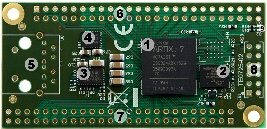
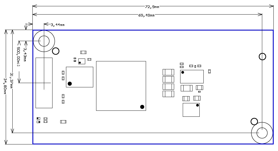
Note that on the images below, there is no POF transceiver, HyperRAM, 50-pin headers and JTAG/UART header installed on the module.
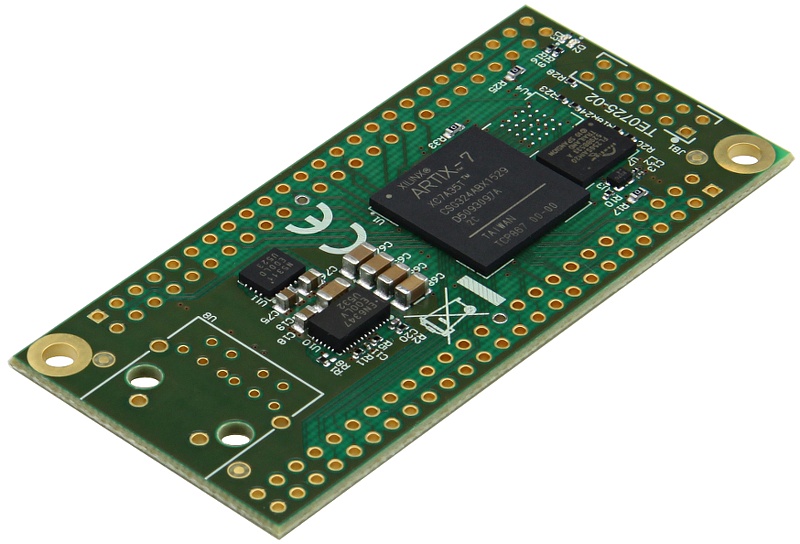
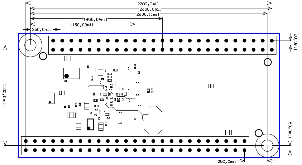
The 2 x 50 pin headers with a 2,54mm standard pitch are perfect for breadboard or low cost dual PCB design.
...
...
...
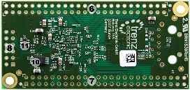
Bottom View
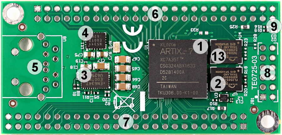

- Xilinx Artix-7 FPGA, U1
- 32-MByte Flash Memory, U7
- Enpirion EN6347 4A PowerSoC DC-DC Step Down Converter, U10
- Enpirion EN5311 1A PowerSoC Synchronous Buck Regulator With Integrated Inductor, U11
- POF Transceiver Placeholderplaceholder, U8
- 50-pin placeholder for breadboard connectionconnector, J1
- 50-pin placeholder for breadboard connectionconnector, J2
- JTAG/UART connector, JB1
- Green LED D2(SYSLED) and Red LED D3(DONE)
- 16K x 8 (128-Kbit) Serial EEPROM, U2
- Low-Noise, High PSRR, RF, 200-mA Low-Dropout Linear Regulator, U9
- Ultralow Supply-Current Voltage Monitor With Optional Watchdog, U9, U6
- Cypress S27KS0641 64-Mbit (8-MByte) HyperRAM™ Self-Refresh DRAM, U4
Key Features
Xilinx Artix-7 XC7A35T (A15 to A100T)
Commercial Temperature Grade (Industrial on Request)
32 MByte Flash Memory
2 x 50 Pin Headers with 2,54mm Pitch, Ideal for Breadboard Use
- 87 IO's IOs (42 + 42 + 3)
- 100 MHz System Clock
- I2C EEPROM
3.3V Single Power Supply with On-Board Voltage Regulators
Size 73 x 35 mm
JTAG/UART Connector
2 LED's
- Optional HyperRAM (8 to 32 MByte)
- Optional POF Fiber Optical Adapter (125/250 MBit/sMbps)
Signals, Interfaces and Pins
...
| Bank | VCCIO | B2B I/O | Notes |
|---|---|---|---|
| 0 | 3.3V | 0 | JTAG |
| 14 | 3.3V | 0 (3) | 3 I/O in XMOD-JTAG - for use as UART |
| 15 | 1.8V | 0 | used for optional hyper RAM |
| 16 | 2.5V | 0 | used for optional optical fiber tranceivertransceiver |
| 34 | User select | 42 | 0R resistor option to select 3.3V |
| 35 | User select | 42 | 0R resistor option to select 3.3V |
...
When using XMOD-JTAG please check the switch settings on XMOD to be sure the power and I/O reference are supplied correctly. TE0790 can be in some cases used to power up TE0725, however this is not recommended. TE0790-01 can not supply enough power for TE0725 (LED may blink but the module is not operating properly, especially in case of larger and more sophisticated designs).
LED's
| LED | Color | FPGA | Notes |
|---|---|---|---|
| D2 | greenGreen | M16 | |
| D3 | redRed | DONE | Active Lowlow |
Connectors
All connectors are are for 100mil headers, all connector locations are in 100 mil grid.
| LED | Color | FPGA | Notes |
|---|---|---|---|
| D2 | greenGreen | M16 | |
| D3 | redRed | DONE | Active Lowlow |
Power and Power-On Sequence
...
| FPGA | Design | Typical Power, 25C ambient |
|---|---|---|
| A35T | not Not configured | TBD* |
| A35T | LED Blinkyblinking | 170mW (typical) |
| A100T | not Not configured | TBD* |
*TBD - To Be Determined.
Actual power consumption depends on the FPGA design and ambient temperature.
...
Please note that two different units are used on the figures below, SI system millimeter(mm) and imperial system thousandth of an inch(mil). This is because of the 100mil pin headers used, see also explanation below. To convert mil's to millimeters and vice versa use formula 100mil's = 2,54mm.
|
| Top View |

|
Bottom View |
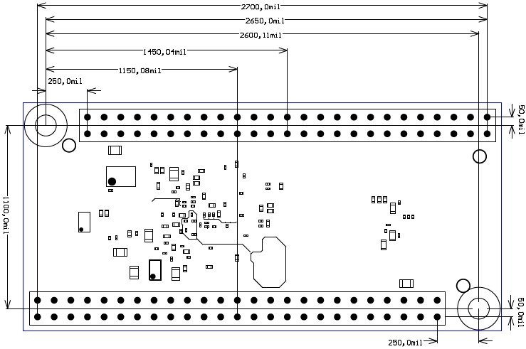
Measurements and placement of the connectors and mounting holes. All 100 mil pin headers are in 100 mil grid, the M3 mounting holes are in 50 mil grid aligned to the centers of the 100mil headers. The module is symmetrical, turning it 180 degrees will keep all I/O and Power pins in both 50 pin headers in compatible places.
...
Commercial grade modules
All parts are conform to at least commercial temperature range of 0°C to +70°C.
...
The module operating temperature range depends on customer design and cooling solution. Please contact us for options.
Weight
...
| Weight g | Note | |
|---|---|---|
| 8.5 | Plain Module |
Revision History
...
| Date | Revision | Contributors | Description |
|---|---|---|---|
| 2017-01-12 | REV03 product images added. | ||
| 2016-12-15 |
| Hardware REV03 specific information added | |
| 2016-12-09 | V40 | Hardware REV02 Block Diagram added | |
| 2016-12-02 | V1
| Initial version |
...
Overview
Content Tools