Page History
...
| SFP+ pin | SFP+ pin Schematic Name | B2B | Note |
|---|---|---|---|
| Transmit Data + (pin 18) | MGT_TX3_P | JB2-26 | - |
| Transmit Data - (pin 19) | MGT_TX3_N | JB2-28 | - |
| Receive Data + (pin 13) | MGT_RX3_P | JB2-25 | - |
| Receive Data - (pin 12) | MGT_RX3_N | JB2-27 | - |
| Receive Fault (pin 2) | MIO10 | JB1-96 | - |
| Receive disable (pin 3) | not connected- | -- | connected to GND |
| MOD-DEF2 (pin 4) | MIO13 | JB1-98 | 3.3V pull-up, (usable I²C SDA/SCL-line) |
| MOD-DEF1 (pin 5) | MIO12 | JB1-100 | 3.3V pull-up, (usable I²C SDA/SCL-line) |
| MOD-DEF0 (pin 6) | MIO11 | JB1-94 | - |
| RS0 (pin 7) | not connected | - | - |
| LOS (pin 8) | MIO0 | JB1-88 | - |
| RS1 (pin 9) | not connected | - | - |
...
The TEBA0841 carrier board is mainly designed for the 4 x 5 SoMs TE0841 and TE0741. This SoMs have GTX-Transceiver units on their FPGA-modules with up to 8 available MGT-lanes. To test this MGT-lanes, 5 RX/TX differential pairs are bridged on-board, hence the transmitted data on this MGT-lanes flows back to their sources in a loop-back circuit without intentional processing or modification.
...
| Note |
|---|
| Note: The mounted TE 4 x 5 SoMs have different schematic net-names of the differential signaling pairs of the MGT-lanes. See Schematic of the particular SoM. |
...
| JX1 pin | JX1 pin Schematic Name | B2B | J3 pin | J3 pin Schematic Name | B2B | |
|---|---|---|---|---|---|---|
| C (pin 4) | TCK | JB3-100 | 4 | TCK | JB3-100 | |
| D (pin 8) | TDO | JB3-98 | 8 | TDO | JB3-98 | |
| F (pin 10) | TDI | JB3-96 | 10 | TDI | JB3-96 | |
| H (pin 12) | TMS | JB3-94 | 12 | TMS | JB3-94 | |
| A (pin 3) | MIO15 | JB1-86 (usable as UART RX- / TX-line) | 3 | MIO15 | JB1-86 (usable as UART RX- / TX-line) | |
| B (pin 7) | MIO14 | JB1-91 (usable as UART RX- / TX-line) | 7 | MIO14 | JB1-91 (usable as UART RX- / TX-line) | |
| E (pin 9) | BOOTMODE | JB1-90 (JTAGSELECT) | 9 | BOOTMODE | JB1-90 (JTAGSELECT) | |
| G (pin 11) | RESIN | JB3-17 | 11 | RESIN | JB3-17 | |
| - | - | - | 15 | CLK0_N | JB2-32 (MGT_CLK0_N, decoupling capacitator 100 nF) | |
| - | - | - | 16 | CLK0_P | JB2-34 (MGT_CLK0_P, decoupling capacitator 100 nF) |
...
The dimensions are given in mm and mil (milli inch).
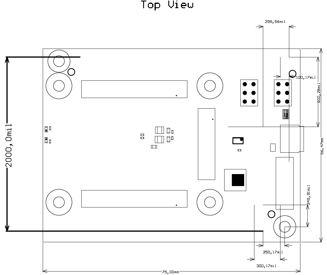
Figure 4: Physical Dimensions of the TEBA0841-01 carrier board
...
| Date | Revision | Authors | Description |
|---|---|---|---|
| 2017-06-0827 | Ali Naseri | current TRM for TEBA0841-01 | |
| 2017-01-30 | 0.1 | Ali Naseri | Initial document |
...
Overview
Content Tools