Page History
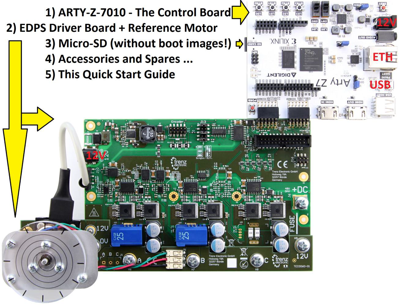
- Insert micro-SD card with downloaded boot images into SD card slot of ARTY-Z.
- Set ARTY-Z Boot Mode to SD (JP4)
- Connect Motor/Driver Board to ARTY-Z so that both PMoD connectors are aligned.
- Attach plastic DEMO load to the motor shaft (optional step).
- Connect a micro-USB Cable (not supplied) to ARTY-Z and to a PC with serial terminal program.
- Connect Ethernet cable (not supplied) to ARTY-Z and wired network with DHCP server.
- Connect power supplies to the ARTY-Z and Driver Board and apply power.
- ARTY-Z will log IP address to serial console, point a web browser to this IP Address.
- It is also possible to view/change the IP Address from console (login/pass are root/root).
- EDDP GUI appears, click "Motor" to start the Motor, it should start spinning.
All jumpers are in default positions: ARTY-Z JP5-REG, JP4-SD and Driver board J13-Single (3 jumpers).
What’s next?
Full Documentation with Design Examples and resource links are available from: Trenz Electronic EDDP Web Hub http://trenz.org/EDDP
1. Check the requirements
- An EDDP Kit.
- A network cable.
- A wired LAN.
- A computer that is:
- Connected to the LAN.
- Capable of running a web browser.
- Capable of editing files on a SD card.
- Has Vivado SDSoC installed to modify the motor control algorithm.
- Micro-USB cable
- Serial terminal program; for example Putty available at https://www.chiark.greenend.org.uk/~sgtatham/putty/latest.html or TeraTerm available at https://ttssh2.osdn.jp/index.html.en.
2. Assemble the demo setup
- Connect the Arty Z7 board Pmod connectors JA, JB to the corresponding Pmod connectors J8,J9 on the TEC0053 board.
- Insert the SD card to the slot on the underside of Arty Z7.
- Connect the power supplies to the Arty Z7 and to the TEC0053.
- Check the motor connection.
- Check the encoder connection.
- Check that the jumpers on the connector J13 on the TEC0053 match the description of the configuration "Single" printed next to the connector.
3. Start motor in the demo setup
- Power up the Arty Z7 10 and the TEC0053 boards.
- Open the serial terminal program.
- Note the IP address either from the serial console or from the DHCP server logs. If the automatic IP address acquisition fails, default IP address of 192.168.42.123 will be used after 10 second timeout.
- Point a web browser to the IP address of the board. An EDDP web site appears.
- Click button "Motor" to start the motor. The button will change color.
- To enable live charts, enable checkbox "Live", which is under the charts.
4. Customize the run-time parameters of the motor control
- Modify the file "focserver.conf" on the SD card to match your needs; most probably "FixedDelay", "RPMKi" and "TorqueKi" are to be changed. See the guide "Embedded Linux Code" for more detailed description.
- Power cycle the Arty Z7 board to reload the parameters.
5. Modify the motor control algorithm
- On the computer, start Vivado SDSoC.
- Create a new SDSoC Application Project based on the custom platform "arty_z7_10_foc" provided in the EDDP and using the sample program "foc".
- In the application, modify the files "src/foc.h" and "src/foc.cpp" to suite your needs.
- Build the SDSoC Application Project. This can take about 15 minutes, depending on the speed of the computer.
- Copy the files from the project directory "Debug\sd_card" to the SD card.
- Insert the SD card to the Arty Z7.
- Power-cycle the Arty Z7.
Overview
Content Tools