Page History
...
| Detail | Option 1: Reference Motor Board with DC +12V Supply | Option 2: Customer Motor at individual DC +5..48V | Comments | ||||
|---|---|---|---|---|---|---|---|
| Motor Supply | From DC +12V Input J7 via Fuse F3 (TODO ... A) | From customer DC Supply to J6 via F1 on Eval Drive Boad | |||||
| Motor Connection | Motor wires connected to cage clamps on Motor Reference Board J5 (A), J4 (B), J3 (C) | Motor wires connected to bolt screw terminals on Eval Board J2 (A), J3 (B), J4 (C) | |||||
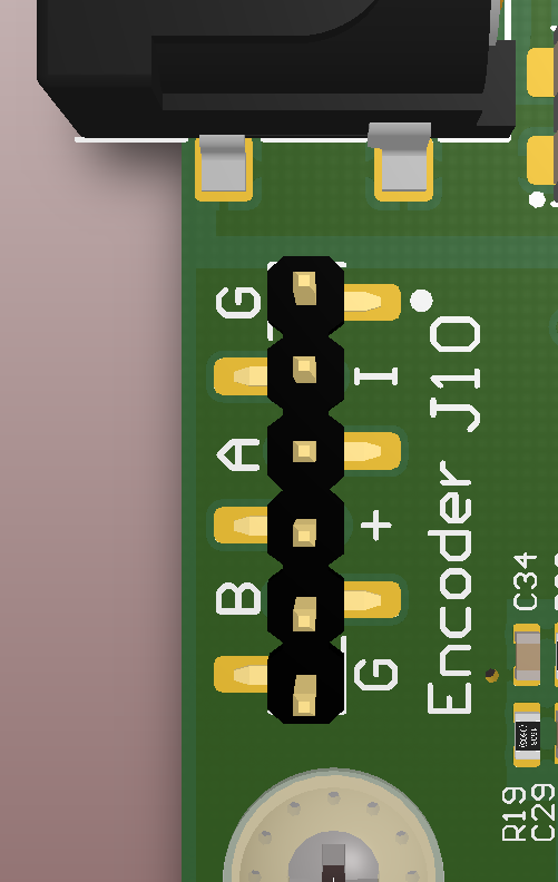
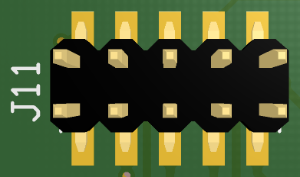
Encoder Connection Single Ended | From encoder pins via ribbon cable 6Pin PMoD to Eval Drive Board J10, Pin 1: GND | From motor to Eval Board J10 (only single ende signals) see left colomn, or Drive Board to J11 (single OR /differential signals): Pin 1: not connected | Jumper Settings for encoder signals.
| ||||
Encoder Connection Differential | J11 differential with 100R terminated: Pin | 1: not connected 2: +5V Supply Pin 3: GND Pin | 4: not connected 5: ENC A negativ Pin 6: ENC A positiv Pin 7: ENC B negativ Pin 8: ENC B positiv Pin 9: ENC I negativ Pin 10: ENC I positiv | Jumper Settings for encoder signals.
|
Internal
Temperature Sensor
...
Overview
Content Tools