Page History
| Scroll pdf ignore | |
|---|---|
|
Key Features
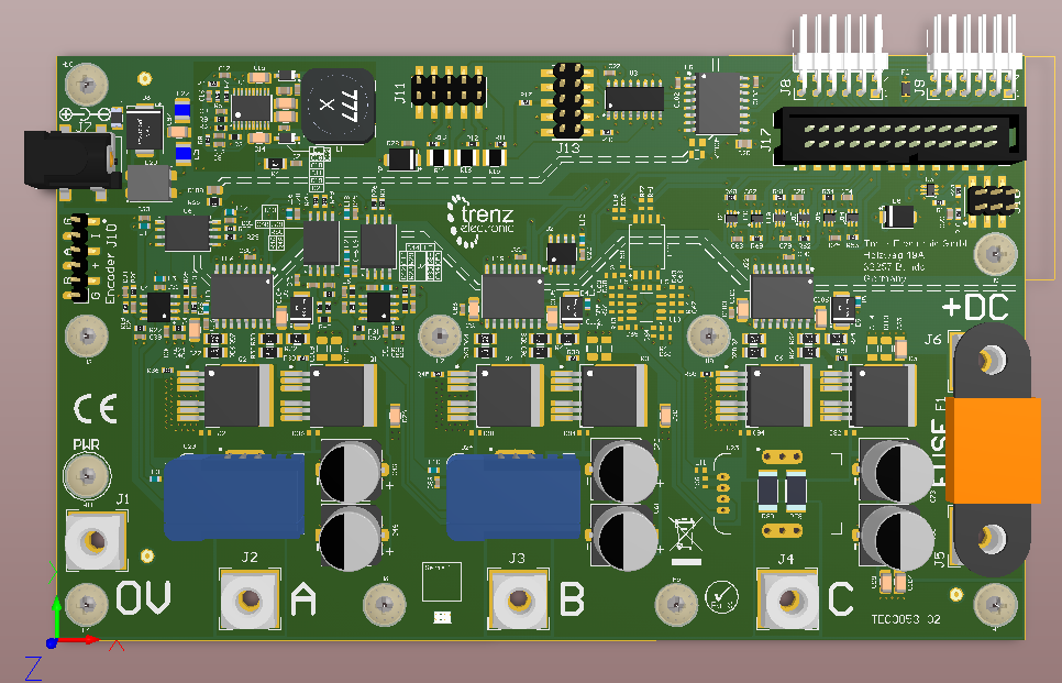
- Motor control evaluation with an suitable controller board
- Quick evaluation with reference motor board
- Power option up to 48V and 30A main supply current
...
- This product is only allowed to be used by an electrical specialist.
- This product is not allowed to be used unattended.
- There is a possible risk of burns due to hot surfaces while running the Board. This e.g. might be caused by an overcurrent at the motor outputs.
- All externally connected power sources must be SELV protected (Separated or safety extra-low voltage).
- For set up the wiring switch off or disconnect all external power supplies.
- During operations it is not allowed to change the wiring or mechanical setup.
- This product is only allowed to be used in a dry indoor environment.
- The product is only allowed to be used in horizontal position on a non-conducting and non-inflammable surface.
- The mechanical setup must ensure that the whole test setup can not be dropped to the floor or moved accidentally.
Signals, Interfaces and Pins
...
| Detail | Option 1: Reference Motor Board with DC +12V Supply | Option 2: Customer Motor at individual DC +5..48V | Comments |
|---|---|---|---|
| Motor Supply | From DC +12V Input J7 via Fuse F3 (TODO ... A) | From customer DC Supply to J6 via F1 on Drive Boad | |
| Motor Connection | Motor wires connected to cage clamps on Motor Reference Board J5 (A), J4 (B), J3 (C) | Motor wires connected to bolt screw terminals on Drive Board J2 (A), J3 (B), J4 (C) | |
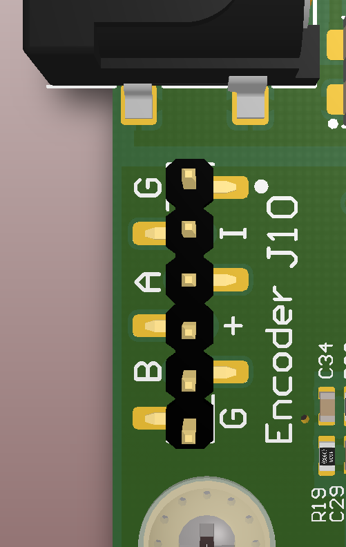
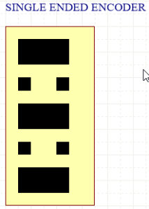
Encoder Connection Single Ended | From encoder pins via 6Pin PMoD to Drive Board J10: Pin 1: GND | From motor to Drive Board to J11 (single/differential): Pin 2: +5V Supply | Jumper Settings for encoder signals.
|
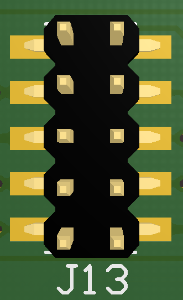
Encoder Connection Differential | J11 differential with 100R terminated: Pin 2: +5V Supply Pin 3: GND Pin 5: ENC A negativ Pin 6: ENC A positiv Pin 7: ENC B negativ Pin 8: ENC B positiv Pin 9: ENC I negativ Pin 10: ENC I positiv |
|

...
Internal
Temperature Sensor
...
The datasheet for the encoder can be found at
http://www.anaheimautomation.com/manuals/accessories/L010390%20-%20Single%20Ended%20Encoder%20with%20Index%20Channel.pdf
Technical Specifications
Absolute Maximum Ratings
...
Overview
Content Tools