Page History
...
There are two options available for the motor and power concept:
| Detail | Option 1: Reference Motor Board with DC +12V Supply | Option 2: Customer Motor at individual DC +5..48V | Comments |
|---|---|---|---|
| Motor Supply | From DC +12V Input J7 via |
fuse F3 (TODO ... A) | From customer DC Supply to J6 via F1 on Drive Boad | ||
| Motor Connection | Motor wires connected to cage clamps on Motor Reference Board J5 (A), J4 (B), J3 (C) | Motor wires connected to bolt screw terminals on Drive Board J2 (A), J3 (B), J4 (C) | |
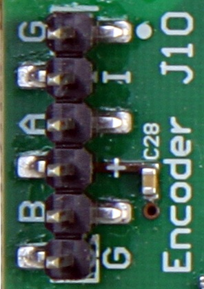
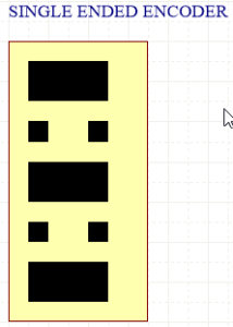
Encoder Connection Single Ended | From encoder pins via 6Pin PMoD to Drive Board J10: Pin 1: GND | From motor to Drive Board to J11 (single/differential): Pin 2: +5V Supply | Jumper Settings for encoder signals.
|
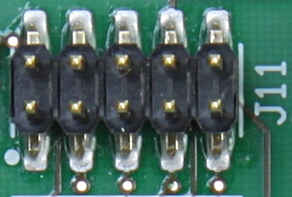
Encoder Connection Differential | J11 differential with 100R terminated: Pin 2: +5V Supply Pin 3: GND Pin 5: ENC A negativ Pin 6: ENC A positiv Pin 7: ENC B negativ Pin 8: ENC B positiv Pin 9: ENC I negativ Pin 10: ENC I positiv |
|
Internal
Temperature Sensor
...
Date | Revision | Authors | Description | ||||||||
|---|---|---|---|---|---|---|---|---|---|---|---|
| Antti Lukats, Andrei Errapart | Initial Versionversion |
Include Page EDPS Disclaimers EDPS Disclaimers
Overview
Content Tools