Page History
...
| Scroll Only (inline) |
|---|
Refer to https://wiki.trenz-electronic.de/display/PD/EDPS+User+Manual for online version of this manual and additional technical documentation of the product. |
Key Features
- Evaluation of the Motor control with the suitable controller board
- Power option up to 48V and 30A main supply current
- MOSFET power stage supporting 3-phase BLDC motors
- Current measurement on 2-phases (3 phase measurement is optional)
- On-board temperature sensor and 1-wire bus connector for additional sensors
- Encoder input capable of receiving both single ended and differential signals
...
Figure 1: Top view of the TEC0053 PCB.
Block Diagram
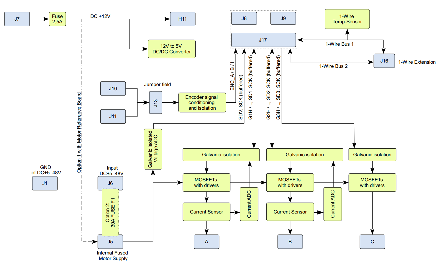
Figure 2: Block diagram of the TEC0053 board.
...
Signals, Interfaces and Pins
Control Board
...
Connectors
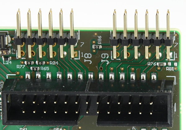
Figure 3: PCB connectors J8 and J9.
...
- only allowed to be used for electrical specialist for the used electrical voltage and power conditions
- only allowed to be used under electrical laboratory conditions
- only allowed to be used in horizontal position on a non-conducting and non-inflammable surface
- only allowed to be used with a wiring, which fulfills the current rating for the maximum possible currents.
- only allowed to be used with a suitable current limiting circuit.
- The maximum continuous current must not exceed 30A.
- The delivered fuse "Littelfuse Tpye 142.5631.5302" must be used as current limiter between connector J5 and J6.
- To limit the current for smaller motor loads an ADDITIONALLY appropriate current limiter can be used e.g. a current limited power source or a fuse integrated in the wiring.
- only allowed to be used with appropriate connectors at the M5 screw connectors, which means M5 cable lugs must be used and fastened according to technical standards.
- only allowed to be used, if the "Drive Boad high current signals" conducting up to 30A nominal, are covered by isolating, mechanically stable, non-inflammable (UL V-1 or better) material
The "Drive Board high current signals" are the motor outputs A, B, C and Fuse F1 Connectors J5 an J6 and further internal connections shown white marked in the following picture:
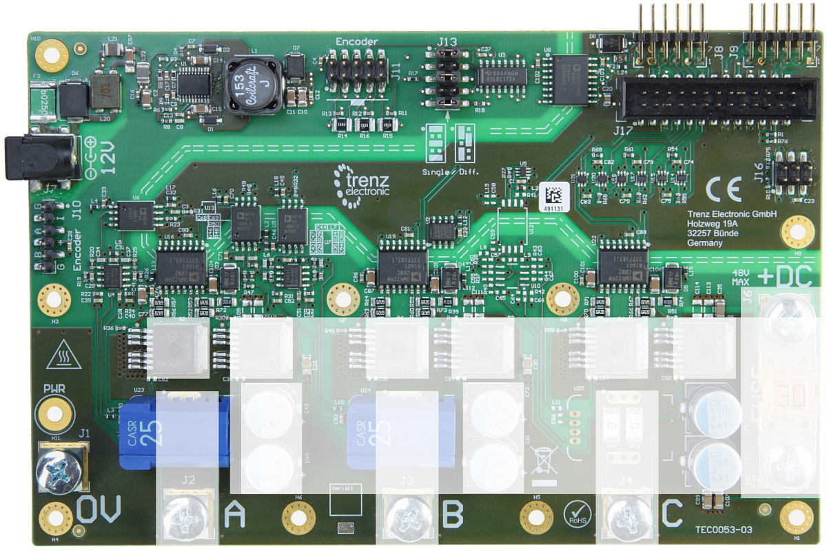
Figure 5: High-current parts of the TEC0053.
It is mandatory to use the delivered isolating cover of the PCB made of plexiglass as a minimum protection. Use holes H1, H9, H3 and H4 with the delivered 10mm spacers when mounting.
...
Figure 6: Top view of the Board with isolating transparent plexiglass cover attached.

Figure 7: Side view of the Board with isolating plexiglass cover.
...
Overview
Content Tools