Page History
...
- Xmod form-factor
- size: 20 x 25 mm
- M3 mounting hole
- Different connector types available
- 2x6 PMOD connector
- JTAG 1-row pin header female
- 2x optional JST Wire-To-Board 6-pin IDC connector
- 2x optional JST Wire-To-Board 10-pin IDC connector
- IDC connectors with different pin-assignment each
Block Diagram
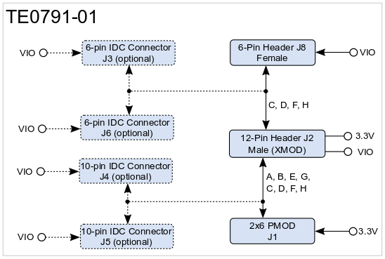
Figure 1: TE0790 TE0791-02 01 block diagram.
Main Components
...
On the TE0791 board are footprints available for 10-pin JST Wire-To-Board IDC connectors J4 and J5 with two different pin-assignments, where all XMOD signals A - H are available. The pin- and signal-assignment with standard System Controller CPLD firmware of the XMOD board are as follows:
usable as GPIO
| Pin Name | J4 Pin Number | J5 Pin Number | Signal | Note |
|---|---|---|---|---|
| A | 1 | 10 | UART TXD | |
| B | 3 | 8 | UART RXD | - |
| C | 2 | 9 | TCK | - |
| D | 4 | 7 | TDO | - |
| E | 5 | 6 | LED on TE0790 | - |
| F | 7 | 5 | TDI | - |
| G | 6 | 4 | Button on TE0790 | - |
| H | 8 | 3 | TMS | - |
| VIO | 9 | 2 | VCC / VCCIO | - |
| GND | 10 | 1 | Ground | - |
...
On the TE0791 board are footprints available for 6-pin JST Wire-To-Board IDC connectors J3 and J6 with two different pin-assignments, where the XMOD signals C, D, F and H are available. The pin- and signal-assignment with At standard System Controller CPLD firmware, this signals create the JTAG interface of the XMOD board are as follows:TDI
| Pin Name | J3 Pin Number | J6 Pin Number | Signal | Note |
|---|---|---|---|---|
| C | 6 | 1 | TCK | - |
| D | 5 | 2 | TDO | - |
| F | 4 | 3 | TDI | - |
| H | 3 | 4 | TDOTMS | - |
| VIO | 2 | 5 | VCC / VCCIO | - |
| GND | 1 | 6 | Ground | - |
Table 4:
Technical Specification
Physical Dimensions
...
Overview
Content Tools