Design Name always "TE Series Name" + Design name, for example "TE0720 Test Board"
HTML
<!--
TemplateRevision 1.2
Basic Notes
- export PDF to download, if vivado revision is changed!
- Template is for different design and SDSoC and examples, remove unused or wrong description!
-->
Scroll Only (inline)
Online version of this manual and other related documents can be found at https://wiki.trenz-electronic.de/display/PD/Trenz+Electronic+Documentation
Scroll pdf ignore
Table of contents
Table of Contents
outline
true
Overview
HTML
<!--
General Design description
 -->
Key Features
HTML
<!--
Add Basic Key Features of the design (should be tested)
 -->
Excerpt
MicroBlaze
I2C
Flash
FMeter
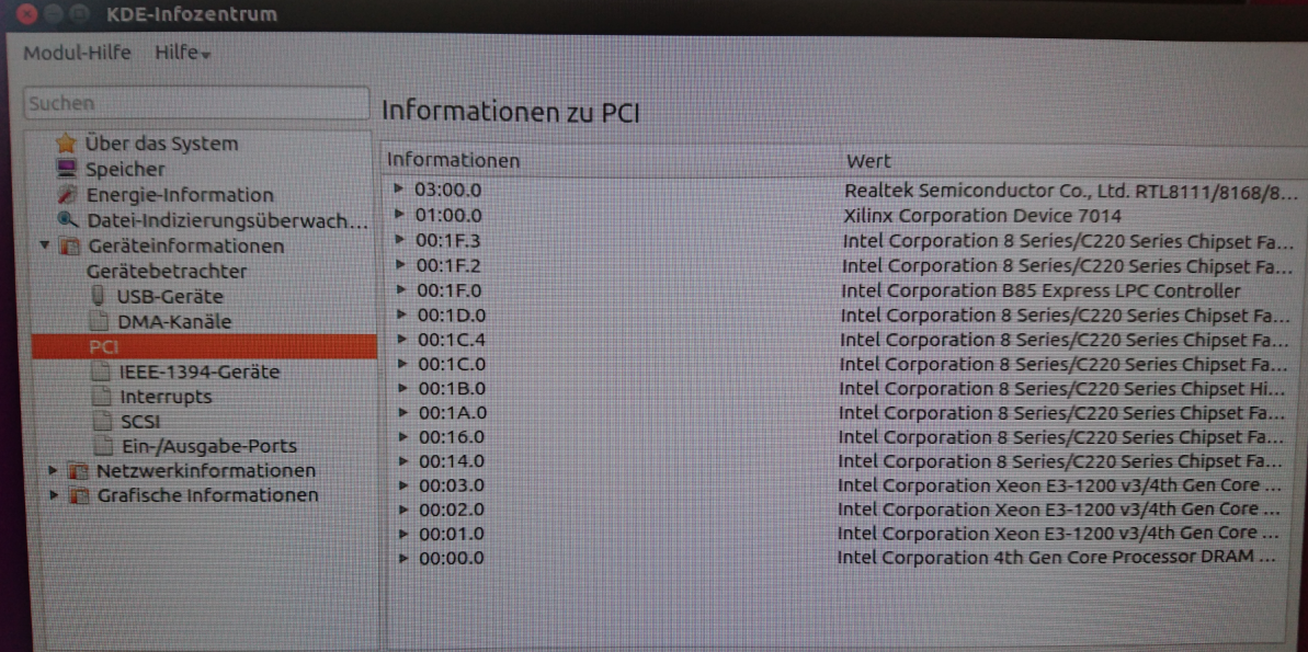
PCIe
SI5338
DDR SODIMM
Revision History
HTML
<!--
- Add changes from design
- Export PDF to download, if vivado revision is changed!
  -->
...
Release Notes and Know Issues
HTML
<!--
- add known Design issues and general Notes for the current revision
 -->
Complete List is available on <design name>/board_files/*_board_files.csv
Design supports following modules:
...
Design supports following carriers:
...
Additional HW Requirements:
...
Content
HTML
<!--
Remove unused content
  -->
For general structure and of the reference design, see Project Delivery
Design Sources
...
tables have all same width (web max 1200px and pdf full page(640px), flexible width or fix width on menu for single column can be used as before) -->
<style>
.wrapped{
  width: 100% !important;
  max-width: 1200px !important;
 }
</style>
Page properties
hidden
true
id
Comments
Important General Note:
Export PDF to download, if vivado revision is changed!
Designate all graphics and pictures with a number and a description, Use "Scroll Title" macro
Use "Scroll Title" macro for pictures and table labels. Figure number must be set manually at the moment (automatically enumeration is planned by scrollPDF)
Figure template (note: inner scroll ignore/only only with drawIO object):
Scroll Title
anchor
Figure_xyz
title
Text
Scroll Ignore
Create DrawIO object here: Attention if you copy from other page, use
Scroll Only
image link to the generate DrawIO PNG file of this page. This is a workaround until scroll pdf export bug is fixed
Table template:
Layout macro can be use for landscape of large tables
Set column width manually(can be used for small tables to fit over whole page) or leave empty (automatically)
Additional Software Template for SDK/HSI and apps_list.csv with settings for HSI
Additional Sources
Scroll Title
anchor
Table_ADS
title
Additional design sources
Scroll Table Layout
orientation
portrait
sortDirection
ASC
repeatTableHeaders
default
style
widths
sortByColumn
1
sortEnabled
false
cellHighlighting
true
Type
Location
Notes
SI5338
<design name>/misc/Si5338
SI5338 Project with current PLL Configuration
Prebuilt
Page properties
hidden
true
id
Comments
Notes :
prebuilt files
Template Table:
Scroll Title
anchor
Table_PF
title
Prebuilt files
Scroll Table Layout
orientation
portrait
sortDirection
ASC
repeatTableHeaders
default
style
widths
sortByColumn
1
sortEnabled
false
cellHighlighting
true
File
File-Extension
Description
BIF-File
*.bif
File with description to generate Bin-File
BIN-File
*.bin
Flash Configuration File with Boot-Image (Zynq-FPGAs)
BIT-File
*.bit
FPGA (PL Part) Configuration File
DebugProbes-File
*.ltx
Definition File for Vivado/Vivado Labtools Debugging Interface
Debian SD-Image
*.img
Debian Image for SD-Card
Diverse Reports
---
Report files in different formats
Hardware-Platform-Specification-Files
*.hdf
Exported Vivado Hardware Specification for SDK/HSI and PetaLinux
LabTools Project-File
*.lpr
Vivado Labtools Project File
MCS-File
*.mcs
Flash Configuration File with Boot-Image (MicroBlaze or FPGA part only)
MMI-File
*.mmi
File with BRAM-Location to generate MCS or BIT-File with *.elf content (MicroBlaze only)
OS-Image
*.ub
Image with Linux Kernel (On Petalinux optional with Devicetree and RAM-Disk)
Software-Application-File
*.elf
Software Application for Zynq or MicroBlaze Processor Systems
SREC-File
*.srec
Converted Software Application for MicroBlaze Processor Systems
Scroll Title
anchor
Table_PF
title
Prebuilt files (only on ZIP with prebult content)
Scroll Table Layout
orientation
portrait
sortDirection
ASC
repeatTableHeaders
default
style
widths
sortByColumn
1
sortEnabled
false
cellHighlighting
true
File
File-Extension
Description
BIT-File
*.bit
FPGA (PL Part) Configuration File
DebugProbes-File
*.ltx
Definition File for Vivado/Vivado Labtools Debugging Interface
Diverse Reports
---
Report files in different formats
Hardware-Platform-Specification-Files
*.hdf
Exported Vivado Hardware Specification for SDK/HSI and PetaLinux
LabTools Project-File
*.lpr
Vivado Labtools Project File
MCS-File
*.mcs
Flash Configuration File with Boot-Image (MicroBlaze or FPGA part only)
MMI-File
*.mmi
File with BRAM-Location to generate MCS or BIT-File with *.elf content (MicroBlaze only)
Software-Application-File
*.elf
Software Application for Zynq or MicroBlaze Processor Systems
SREC-File
*.srec
Converted Software Application for MicroBlaze Processor Systems
Download
Reference Design is only usable with the specified Vivado/SDK/PetaLinux/SDx version. Do never use different Versions of Xilinx Software for the same Project.
Page properties
hidden
true
id
Comments
Important set new Vivado version link on every Design update of new vivado version!
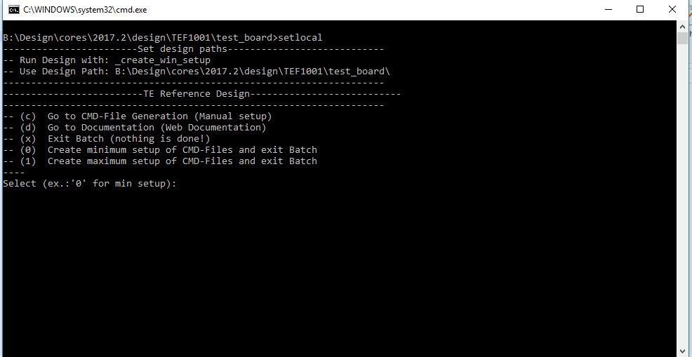
The Trenz Electronic FPGA Reference Designs are TCL-script based project. Command files for execution will be generated with "_create_win_setup.cmd" on Windows OS and "_create_linux_setup.sh" on Linux OS.
TE Scripts are only needed to generate the vivado project, all other additional steps are optional and can also executed by Xilinx Vivado/SDK GUI. For currently Scripts limitations on Win and Linux OS see: Project Delivery Currently limitations of functionality
_create_win_setup.cmd/_create_linux_setup.sh and follow instructions on shell: Image Added
Press 0 and enter for minimum setup
(optional Win OS) Generate Virtual Drive or use short directory for the reference design (for example x:\<design name>)
Create Project
Select correct device and Xilinx install path on "design_basic_settings.cmd" and create Vivado project with "vivado_create_project_guimode.cmd" Note: Select correct one, see TE Board Part Files
Create HDF and export to prebuilt folder
Run on Vivado TCL: TE::hw_build_design -export_prebuilt Note: Script generate design and export files into \prebuilt\hardware\<short dir>. Use GUI is the same, except file export to prebuilt folder
Generate Programming Files with HSI/SDK
Start with TE Scripts on Vivado TCL: TE::sw_run_hsi (optional) Start SDK with Vivado GUI or start with TE Scripts on Vivado TCL: TE::sw_run_sdk to generate files manually Note: See SDK Projects
(optional )Copy "prebuilt\software\<short dir>\srec_spi_bootloader.elf" into "\firmware\microblaze_0" (replace shipped one) and regenerate design again (HW (Step5)+SW(Step6 only a.))
Launch
Programming
Page properties
hidden
true
id
Comments
Note:
Programming and Startup procedure
Note
Check Module and Carrier TRMs for proper HW configuration before you try any design.
Open Vivado Project with "vivado_open_existing_project_guimode.cmd" or if not created, create with "vivado_create_project_guimode.cmd"
Type on Vivado TCL Console: TE::pr_program_flash_mcsfile -swapp hello_tef1001
Reboot PC
SD
Not supported.
JTAG
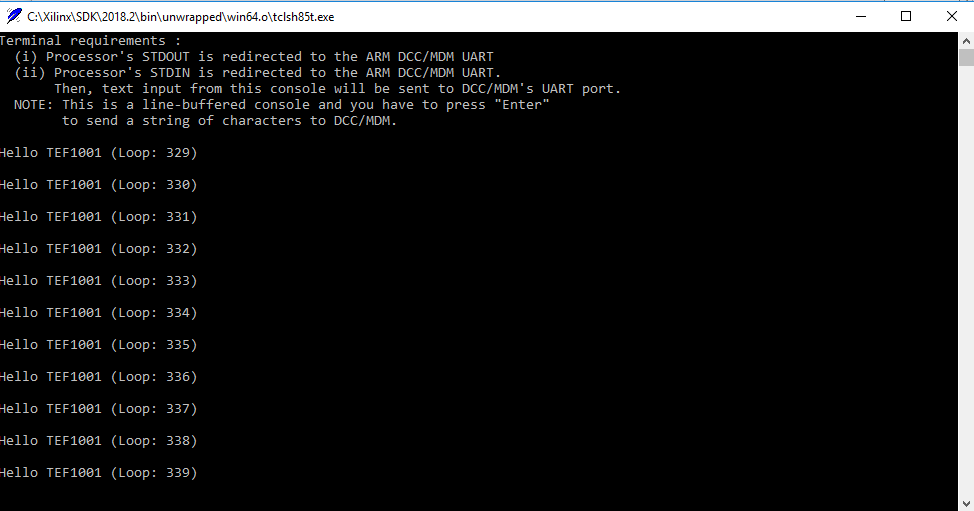
Connect Vivado HW Manager and program FPGA Note: PCIe enumeration will be not done in this case. SREC Bootloader need Hello TEF1001 application on QSPI Flash for output
Power On PCB Note: 1. FPGA Load Bitfile into FPGA, modified SREC Bootloader configure SI5338 and load application from QSPI into DDR (Depends on linker script)
JTAG/UART Console:
Launch the XSDB console on SDK (Xilinx → XSCT Console):
add notes for the signal either groups or topics, for example:
Control:
add controllable IOs with short notes..
Monitoring:
add short notes for signals which will be monitored only
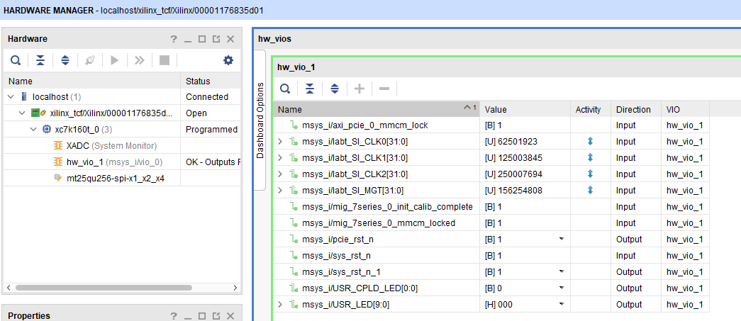
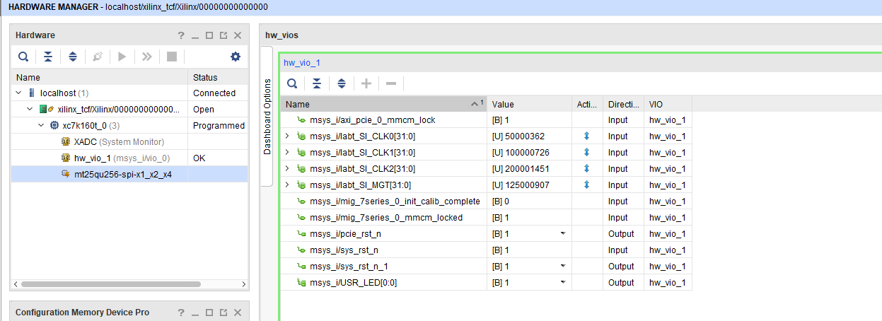
SI5338_CLK0 Counter:
Open Vivado HW-Manager and add VIO signal to dashboard (*.ltx located on prebuilt folder).Set radix from VIO signals to unsigned integer.Note: Frequency Counter is inaccurate and displayed unit is Hz
Open Vivado HW Manager
Add VIO to Dashboard:
Set Radix to unsigned integer for FMeterCLKs (labt_SI_*)
Control:
USER LEDs are selectable Note USR_CPLD_LED on PCB REV1 and REV02, USR_LED Matrix only on REV02
General documentation how you work with these project will be available on Si5338
Appx. A: Change History and Legal Notices
Document Change History
To get content of older revision got to "Change History" of this page and select older document revision number.
Page properties
hidden
true
id
Comments
Note this list must be only updated, if the document is online on public doc!
It's semi automatically, so do following
Add new row below first
Copy "Page Information Macro(date)" Macro-Preview, Metadata Version number, Author Name and description to the empty row. Important Revision number must be the same as the Wiki document revision number Update Metadata = "Page Information Macro (current-version)" Preview+1 and add Author and change description. --> this point is will be deleted on newer pdf export template
Metadata is only used of compatibility of older exports
Scroll Title
anchor
Table_dch
title
Document change history.
Scroll Table Layout
orientation
portrait
sortDirection
ASC
repeatTableHeaders
default
style
widths
2*,*,3*,4*
sortByColumn
1
sortEnabled
false
cellHighlighting
true
Date
Document Revision
Authors
Description
Page info
modified-date
modified-date
dateFormat
yyyy-MM-dd
Page info
infoType
Current version
dateFormat
yyyy-MM-dd
prefix
v.
type
Flat
Page info
infoType
Modified by
dateFormat
yyyy-MM-dd
type
Flat
typo correction part name
typo correction on programming chapter
note pcie
v.9
John Hartfiel
add -410 assembly variant
v.8
John Hartfiel
2018.2 release
v.6
John Hartfiel
2017.4 release
2018-02-08
v.5
John Hartfiel
2017.2 release
2017-11-28
v.1
John Hartfiel
initial release
--
all
Page info
infoType
Modified users
dateFormat
yyyy-MM-dd
type
Flat
--
Additional Sources
...
Prebuilt
HTML
<!--

<table width="100%">
<tr> <th>File                                 </th> <th>File-Extension</th>  <th>Description                                                                              </th> </tr>
<tr> <td>BIF-File                             </td> <td>*.bif         </td>  <td>File with description to generate Bin-File                                               </td> </tr>
<tr> <td>BIN-File                             </td> <td>*.bin         </td>  <td>Flash Configuration File with Boot-Image (Zynq-FPGAs)                                    </td> </tr>
<tr> <td>BIT-File                             </td> <td>*.bit         </td>  <td>FPGA Configuration File                                                                  </td> </tr>
<tr> <td>DebugProbes-File                     </td> <td>*.ltx         </td>  <td>Definition File for Vivado/Vivado Labtools Debugging Interface                           </td> </tr>
<tr> <td>Debian SD-Image                      </td> <td>*.img         </td>  <td>Debian Image for SD-Card                                                                </td> </tr>
<tr> <td>Diverse Reports                      </td> <td>  ---         </td>  <td>Report files in different formats                                                        </td> </tr>
<tr> <td>Hardware-Platform-Specification-Files</td> <td>*.hdf         </td>  <td>Exported Vivado Hardware Specification for SDK/HSI                                       </td> </tr>
<tr> <td>LabTools Project-File                </td> <td>*.lpr         </td>  <td>Vivado Labtools Project File                                                             </td> </tr>
<tr> <td>MCS-File                             </td> <td>*.mcs         </td>  <td>Flash Configuration File with Boot-Image (MicroBlaze or FPGA part only)                  </td> </tr>
<tr> <td>MMI-File                             </td> <td>*.mmi         </td>  <td>File with BRAM-Location to generate MCS or BIT-File with *.elf content (MicroBlaze only) </td> </tr>
<tr> <td>OS-Image                             </td> <td>*.ub          </td>  <td>Image with Linux Kernel (On Petalinux optional with Devicetree and RAM-Disk)             </td> </tr>
<tr> <td>Software-Application-File            </td> <td>*.elf         </td>  <td>Software Application for Zynq or MicroBlaze Processor Systems                            </td> </tr>
<tr> <td>SREC-File                            </td> <td>*.srec        </td>  <td>Converted Software Application for MicroBlaze Processor Systems                          </td> </tr>
</table>
-->
...
File
...
File-Extension
...
Description
...
MCS-File
...
*.mcs
...
Flash Configuration File with Boot-Image (MicroBlaze or FPGA part only)
...
MMI-File
...
*.mmi
...
File with BRAM-Location to generate MCS or BIT-File with *.elf content (MicroBlaze only)
...
Download
Reference Design is only usable with the specified Vivado/SDK/PetaLinux/SDx version. Do never use different Versions of Xilinx Software for the same Project.
The Trenz Electronic FPGA Reference Designs are TCL-script based project. Command files for execution will be generated with "_create_win_setup.cmd" on Windows OS and "_create_linux_setup.sh" on Linux OS.
TE Scripts are only needed to generate the vivado project, all other additional steps are optional and can also executed by Xilinx Vivado/SDK GUI. For currently Scripts limitations on Win and Linux OS see: Project Delivery Currently limitations of functionality
_create_win_setup.cmd/_create_linux_setup.sh and follow instructions on shell: Image Removed
Press 0 and enter for minimum setup
(optional Win OS) Generate Virtual Drive or use short directory for the reference design (for example x:\<design name>)
Create Project
Select correct device and Xilinx install path on "design_basic_settings.cmd" and create Vivado project with "vivado_create_project_guimode.cmd" Note: Select correct one, see TE Board Part Files
Create HDF and export to prebuilt folder
Run on Vivado TCL: TE::hw_build_design -export_prebuilt Note: Script generate design and export files into \prebuilt\hardware\<short dir>. Use GUI is the same, except file export to prebuilt folder
Generate Programming Files with HSI/SDK
Start SDK with Vivado GUI or start with TE Scripts on Vivado TCL: TE::sw_run_sdk Note: See SDK Projects
Create SI5338 Firmware Example project
(only without DDR on SODIMM) Change Linker Script to BlockRAM (lscript.ld)
Regenerate Design
(optional Block RAM Update) Copy SI5338.elf into "test_board\firmware\microblaze_0" and regenerate Design with TE::hw_build_design -export_prebuilt
Launch
Programming
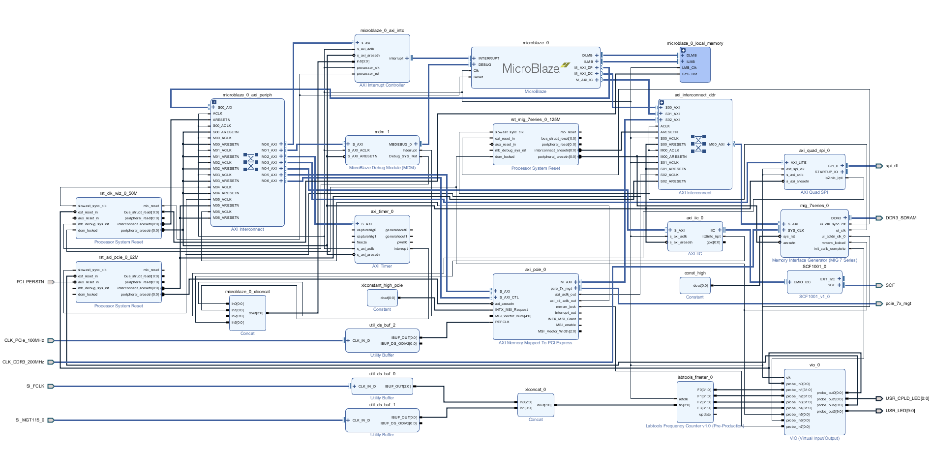
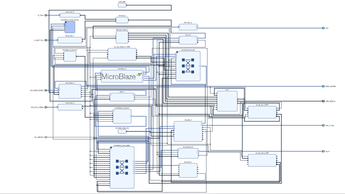
HTML
<!--
Description of Block Design, Constrains...
BD Pictures from Export...
  -->
Note
Check Module and Carrier TRMs for proper HW configuration before you try any design.
Open Vivado HW Manager with: TE::pr_init_hardware_manager
Select generated mcs and prm file: test_board/prebuilt/hardware/<assembly option>/ and test_board/prebuilt/hardware/<assembly option>/reports/
Configure Flash
Reboot PC
HTML
<!--
Example:
Connect JTAG and power on PCB
(if not done) Select
correct device and Xilinx install path on "design_basic_settings.cmd"
and create Vivado project with "vivado_create_project_guimode.cmd" or
open with "vivado_open_project_guimode.cmd", if generated.
Type on Vivado Console: TE::pr_program_flash_mcsfile -swapp u-boot
Note: Alternative use SDK or setup Flash on Vivado manually
Reboot (if not done automatically)

   -->
<!--
Add Description for other Software, for example SI CLK Builder ...
 -->
SI5338 CLKBuilder
Open Register Map File:"\test_board\misc\SI5338\RegisterMap.txt"
Change CLK if needed
Save project and generate "register_map.h"
Overwrite "register_map.h" from SI5338 Init Application with generate file
Appx. A: Change History and Legal Notices
Document Change History
To get content of older revision got to "Change History" of this page and select older document revision number.
HTML
<!--
Generate new entry:
1:add new row below first
2:Copy Page Information Macro(date+user) Preview, Page Information Macro Preview
3.Update Metadate =Page Information Macro Preview+1
  -->