Page History
...
For general structure and of the reference design, see Project Delivery - AMD devices
Design Sources
| Type | Location | Notes |
|---|---|---|
| Vivado | <design name>/block_design <design name>/constraints <design name>/ip_lib <design name>/firmware | Vivado Project will be generated by TE Scripts |
| SDK/HSI | <design name>/sw_lib | Additional Software Template for SDK/HSI and apps_list.csv with settings for HSI |
| PetaLinux | <design name>/os/petalinux | PetaLinux template with current configuration |
...
Trenz Electronic provides a tcl based built environment based on Xilinx Design Flow.
See also:Vivado/SDK/SDSoCAMD Development Tools#XilinxSoftware-BasicUserGuides
- AMD Development Tools#XilinxSoftware-BasicUserGuidesVivado/SDK/SDSoC
- Vivado Projects - TE Reference Design
- Project Delivery.
The Trenz Electronic FPGA Reference Designs are TCL-script based project. Command files for execution will be generated with "_create_win_setup.cmd" on Windows OS and "_create_linux_setup.sh" on Linux OS.
TE Scripts are only needed to generate the vivado project, all other additional steps are optional and can also executed by Xilinx Vivado/SDK GUI. For currently Scripts limitations on Win and Linux OS see: Project Delivery Currently limitations of functionality
- _create_win_setup.cmd/_create_linux_setup.sh and follow instructions on shell:
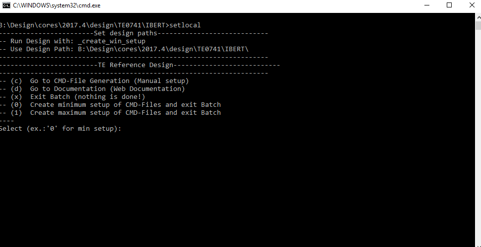
- Press 0 and enter for minimum setup
- (optional Win OS) Generate Virtual Drive or use short directory for the reference design (for example x:\<design name>)
- Create Project
- Select correct device and Xilinx install path on "design_basic_settings.cmd" and create Vivado project with "vivado_create_project_guimode.cmd"
Note: Select correct one, see TE Board Part Files
- Select correct device and Xilinx install path on "design_basic_settings.cmd" and create Vivado project with "vivado_create_project_guimode.cmd"
- Create HDF and export to prebuilt folder
- Run on Vivado TCL: TE::hw_build_design -export_prebuilt
Note: Script generate design and export files into \prebuilt\hardware\<short dir>. Use GUI is the same, except file export to prebuilt folder
- Run on Vivado TCL: TE::hw_build_design -export_prebuilt
- Generate MCS Firmware (optional):
- Create SDK Project with TE Scripts on Vivado TCL: TE::sw_run_sdk
- Create "SCU" application
Note: Select MCS Microblaze and SCU Application - Select Release Built
- Regenerate App
- (optional) Copy "\\workspace\sdk\scu\Release\scu.elf" into "\firmware\microblaze_mcs_0\"
- Regenerate Vivado Project or Update Bitfile only with "scu.elf"
...
Xilinx documentation for programming and debugging: Vivado/SDK/SDSoC-Xilinx Software Programming and Debugging
QSPI
- Connect JTAG and power on PCB
- (if not done) Select correct device and Xilinx install path on "design_basic_settings.cmd" and create Vivado project with "vivado_create_project_guimode.cmd" or open with "vivado_open_project_guimode.cmd", if generated.
- Type on Vivado Console: TE::pr_program_flash_mcsfile -swapp u-boot
Note: Alternative use SDK or setup Flash on Vivado manually - Reboot (if not done automatically)
...
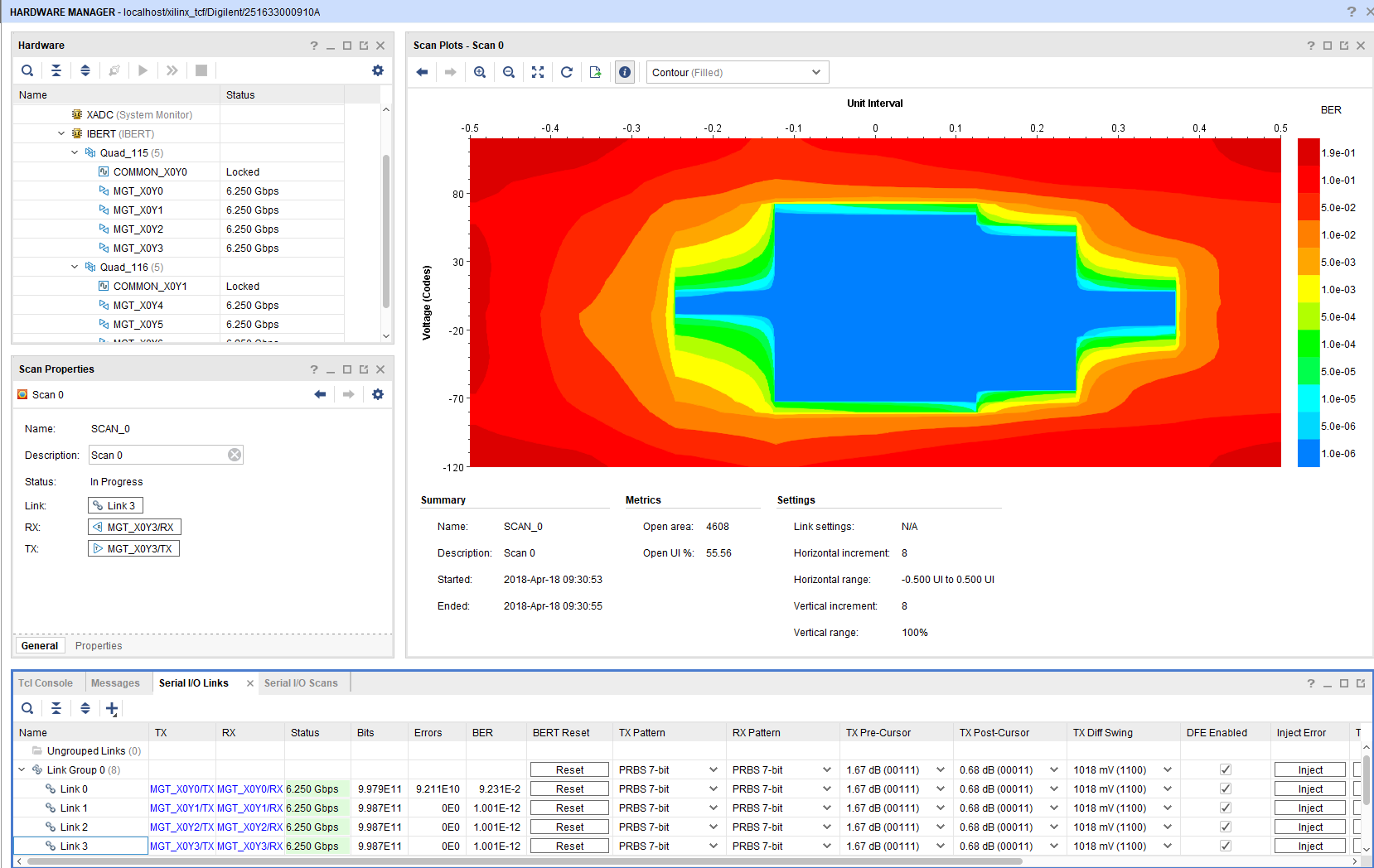
- Open Vivado HW-Manager
- "Refresh device" is needed after Bitfile programming, because MCS reconfigure SI5338 and enables IBERT a little bit later.
- loopback depends on TEB0841 Revision an connection
| IBERT | Component Name | Net Name | TEB0841 |
|---|---|---|---|
| X0Y0 | 115-0 | MGT4 | loop back RX/TX. Note: N.C. on TEB0841-01, use internal loopback |
| X0Y1 | 115-1 | MGT5 | loopback over SD Pin header possible |
| X0Y2 | 115-2 | MGT6 | loop back RX/TX |
| X0Y3 | 115-3 | MGT7 | loop back RX/TX |
| X0Y4 | 116-0 | MGT0 | loop back RX/TX |
| X0Y5 | 116-1 | MGT1 | loop back RX/TX |
| X0Y6 | 116-2 | MGT2 | loop back RX/TX |
| X0Y7 | 116-3 | MGT3 | loopback over sfp possible |
System Design - Vivado
| HTML |
|---|
<!-- Description of Block Design, Constrains... BD Pictures from Export... --> |
...
Overview
Content Tools