Page History
...
| Scroll Title | ||||||||||||||||||||||||||||||||
|---|---|---|---|---|---|---|---|---|---|---|---|---|---|---|---|---|---|---|---|---|---|---|---|---|---|---|---|---|---|---|---|---|
| ||||||||||||||||||||||||||||||||
|
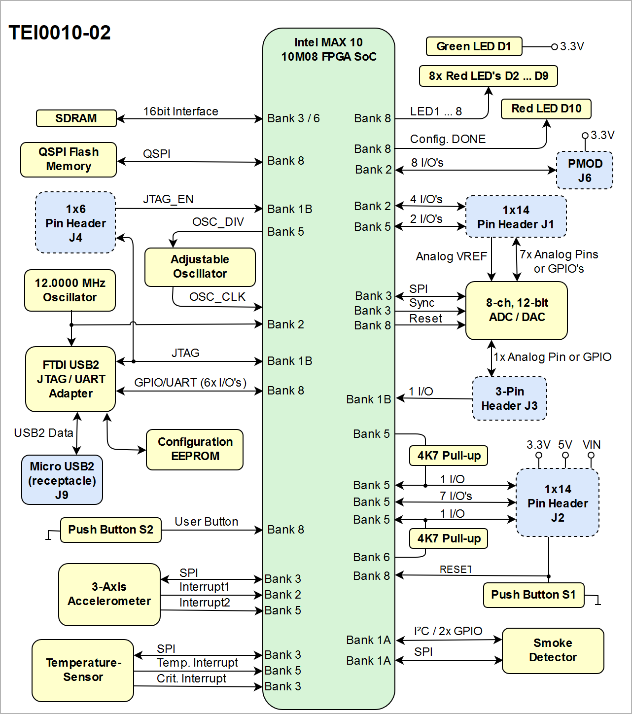
Main Components
| Page properties | ||||
|---|---|---|---|---|
| ||||
Notes :
|
| Scroll Title | ||||||||||||||||||||||||||||||||
|---|---|---|---|---|---|---|---|---|---|---|---|---|---|---|---|---|---|---|---|---|---|---|---|---|---|---|---|---|---|---|---|---|
| ||||||||||||||||||||||||||||||||
|
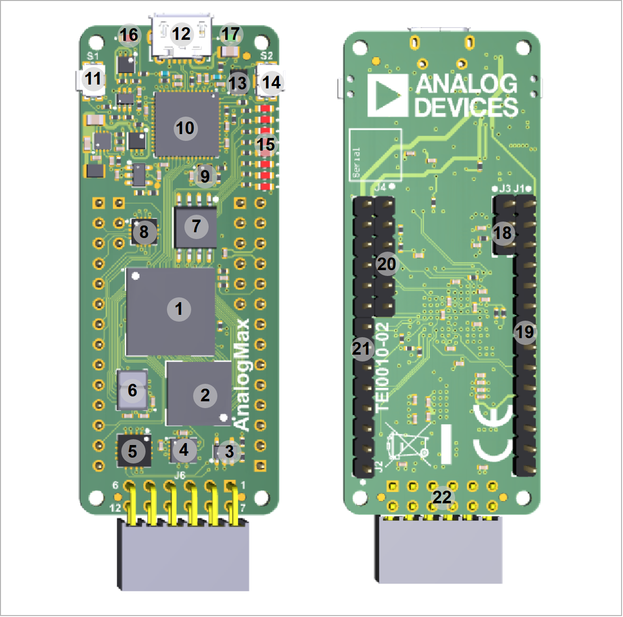
- Intel MAX 10 10M08 FPGA SoC, U1
- 8 Mbyte SDRAM 166MHz, U2
- LT LTC1799 oscillator, U10
- Analog Devices ADXL362BCCZ MEMS 3-axis accelerometer, U11
- Analog Devices ADT7320UCPZ temperature sensor, U8
- Analog Devices ADPD188BI smoke detector, U14
- Winbond W74M64FV QSPI Flash memory, U5
- Analog Devices AD5592RBCPZ ADC/DAC, U12
- 12.0000 MHz MEMS oscillator, U7
- FTDI USB2 to JTAG/UART adapter, U3
- Push button (reset), S1
- Micro USB2 B socket (receptacle), J9
- Configuration EEPROM for FTDI chip, U9
- Push button (user), S2
- 8x red user LEDs, D2 ... D9
- Red LED (Conf. DONE), D10
- Green LED (indicating 3.3V supply voltage), D1
- 3-pin header (2.54mm pitch), J3
- 1x14 pin header (2.54mm pitch), J1
- 1x6 pin header (2.54mm pitch), J4
- 1x14 pin header (2.54mm pitch), J2
- 2x6 Pmod connector, J6
...
Overview
Content Tools