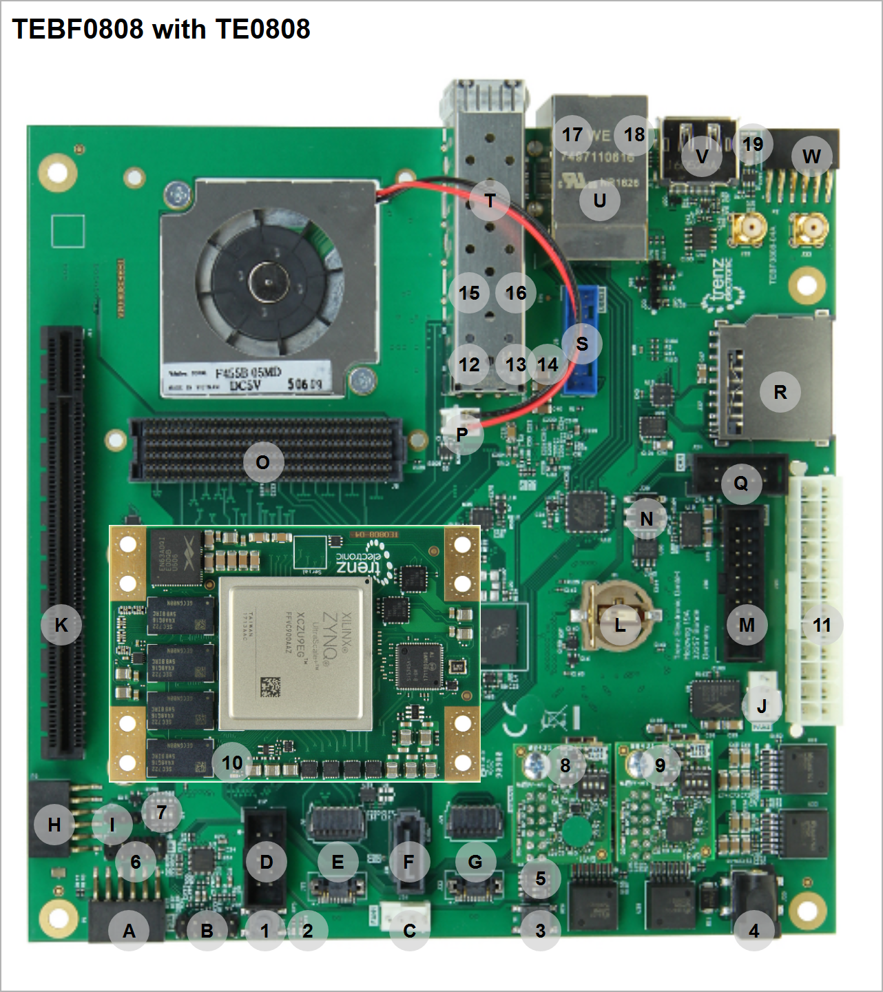
| Number | Note |
| Letter | Note |
|---|
| 1 | S2- Reset Button |
| A | P1 - PMOD 3.3V I2C Bus |
|---|
| 2 | D7 - LED D7 Red (Usage: status) || D6 - LED Green (Usage: status) |
| B | J9 - Audio Enclosure |
|---|
| 3 | S1 - Reset Button |
| CP3 | - PMOD 3.3V I2C BusJ26 - FAN1 12V |
|---|
| 4 | J25 - Power Jack J25, 2.1mm (optional 12V power input) |
| D | J17 - I2C (for optional module PLL access) |
|---|
| 5 | S5 - DIP Switch for Boot Mode and FMCVADJ |
| E | J6/15 - Firefly - GTH GTH |
|---|
| 6 | J10 - Enclosure Pin header(Reset and Power Button, HD LED (Usage: status/user) and Power LED (Usage: status/user)) |
| F | J31 - SATA |
|---|
| 7 | S4 - DIP Switch for CPLD access and power control |
| G | J21/22 - Firefly - loopback only |
|---|
| 8 | J12 - XMOD with green dot for Module JTAG and UART, XMOD LED D4 Red used for status information |
| HJ11 | - PCIe (1x)P3 - PMOD 3.3V I2C Bus |
|---|
| 9 | J28 - XMOD for CPLD,FMC JTAG and Firmware ID over UART(need CPLD Firmware 7 or newer) , XMOD LED D4 Red used for status information |
| I | J30 J34 - PJTAGI2C Firefly |
|---|
| 10 | FPGA Done LED (location varies slightly on different module series ) |
| J | J5 - FMC HPCJ35 - FAN2 12V |
|---|
| 11 | J20 - ATX Power Connector (Main 12V and 5V Power supply), recommended power supply connector |
| K | J24 - CANJ11 - PCIe (1x) |
|---|
| 12 | D1 - SFP LED Red (Usage: status/user) |
| LJ8 | - USB 3.0 (2x) EnclosureB1 - Battery holder CR1220 |
|---|
| 13 | D8 - SFP LED Green (Usage: status/user) |
| M | J27 J30 - SDPJTAG |
|---|
| 14 | D9 - SFP LED Red (Usage: status/user) |
| N | J14 J29 - SFP CAN (2xsame as J24) |
|---|
| 15 | D10 - SFP LED Green (Usage: status/user) |
| OJ7 | - USB 3.0 (2x), ETH (1x)J5 - FMC HPC |
|---|
| 16 | J7 - ETH LED Yellow (Usage: status) |
| PJ13 | - Displayport (1x)J19 - FAN3 5V |
|---|
| 17 | J7 - ETH LED Green/Orange (Usage: status) |
| QP2 - PMOD 3.3V FPG IOs || Bottom side: J16 - microSD | J24 - CAN (same as J29) |
|---|
| 18 | D4 - LED Green (Usage: status/user) || D5 - LED Red (Usage: status/user) |
| R | J27 - SD |
|---|
|
|
| S | J8 - USB 3.0 (2x) Enclosure |
|---|
|
|
| T | J14 - SFP (2x) |
|---|
|
|
| U | J7 - USB 3.0 (2x), ETH (1x) |
|---|
|
|
| V | J13 - Displayport (1x) |
|---|
|
|
| W | P2 - PMOD 3.3V FPG IOs |
|---|
|
|
| W(b) | Bottom side: J16 - microSD |
|---|