...
Block Diagram
| Page properties |
|---|
|
add drawIO object here.
|
...
| Scroll Title |
|---|
| anchor | Figure_OV_BD |
|---|
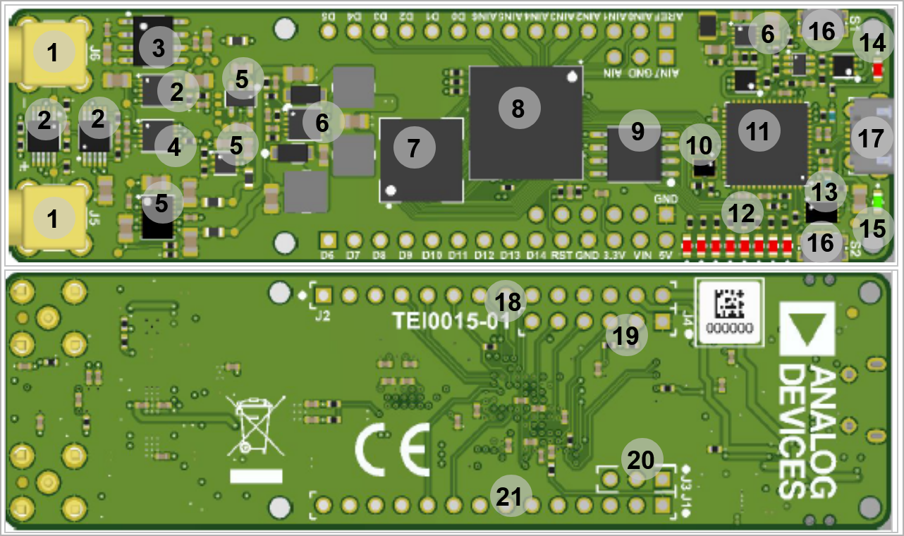
| title | TEI0015 main components |
|---|
|
| Scroll Ignore |
|---|
| draw.io Diagram |
|---|
| border | false |
|---|
| viewerToolbar | true |
|---|
| |
|---|
| fitWindow | false |
|---|
| diagramDisplayName | |
|---|
| lbox | true |
|---|
| revision | 13 |
|---|
| diagramName | TEI0015_OV_MC |
|---|
| simpleViewer | false |
|---|
| width | |
|---|
| links | auto |
|---|
| tbstyle | hidden |
|---|
| diagramWidth | 641 |
|---|
|
|
| Scroll Only |
|---|
|
|
- SMA Connector, J5...6
- Amplifier, U12- U14- U6
- Series Voltage Reference, U8
- Analog to Digital Convertor, U15
- Voltage Regulator, U10- U13- U16
- Switching Voltage Regulator, U11- U4
- Intel® MAX 10, U1
- SDRAM Memory, U2
- SPI Flash Memory, U5
- 12.00 MHz MEMS oscillator, U7
- FTDI USB2 to JTAG/UART adapter, U3
- User LEDs, D2...9
- 4Kb EEPROM, U9
- Configuration LED (Red) , D10
- Power-on LED (Green), D1
- Push button, S1...2
- Micro USB2 Receptacle, J9
- 1x14 pin header header (Not assembled), J2
- 1x6 pin header header (Not assembled), J4
- Jumper, J3
- 1x14 pin header header (Not assembled), J1
Initial Delivery State
| Page properties |
|---|
|
Notes : Only components like EEPROM, QSPI flash and DDR3 can be initialized by default at manufacture. If there is no components which might have initial data ( possible on carrier) you must keep the table empty |
...
| Scroll Title |
|---|
| anchor | Table_OBP_USB |
|---|
| title | Micro USB-2 connector pins |
|---|
|
| Scroll Table Layout |
|---|
| orientation | portrait |
|---|
| sortDirection | ASC |
|---|
| repeatTableHeaders | default |
|---|
| style | |
|---|
| widths | |
|---|
| sortByColumn | 1 |
|---|
| sortEnabled | false |
|---|
| cellHighlighting | true |
|---|
|
| Pins | Connected to | Note |
|---|
| VBUS | USB_VBUS | It is connected to GND | | D+ | FTDI FT2232H U3, DP pin |
| | D- | FTDI FT2232H U3, DM pin |
|
|
JTAG Interface
JTAG access to the TEI0015 SoM through pin header connector J4.
| Scroll Title |
|---|
| anchor | Table_SIP_JTG |
|---|
| title | JTAG pins connection |
|---|
|
| Scroll Table Layout |
|---|
| orientation | portrait |
|---|
| sortDirection | ASC |
|---|
| repeatTableHeaders | default |
|---|
| style | |
|---|
| widths | |
|---|
| sortByColumn | 1 |
|---|
| sortEnabled | false |
|---|
| cellHighlighting | true |
|---|
|
JTAG Signal | Pin Header Connector | Note |
|---|
| TMS | J4-6 |
| | TDI | J4-5 |
| | TDO | J4-4 |
| | TCK | J4-3 |
| | JTAG_EN | J4-2 |
|
|
...
| Scroll Title |
|---|
| anchor | Table_OBP |
|---|
| title | On board peripherals |
|---|
|
| Scroll Table Layout |
|---|
| orientation | portrait |
|---|
| sortDirection | ASC |
|---|
| repeatTableHeaders | default |
|---|
| style | |
|---|
| widths | |
|---|
| sortByColumn | 1 |
|---|
| sortEnabled | false |
|---|
| cellHighlighting | true |
|---|
|
|
...
Module size: 25 mm × 86.5 mm. Please download the assembly diagram for exact numbers.
PCB thickness: 1.65 22 mm.
| Page properties |
|---|
|
In 'Physical Dimension' section, top and button view of moduloe must be insterted, information regarding physical dimention can be obtained through webpage for product in Shop.Trenz, (Download> Documents> Assembly part)for every SoM. For Example: for Module TE0728, Physical Dimension information can be captured by snipping tools from the link below: https://www.trenz-electronic.de/fileadmin/docs/Trenz_Electronic/Modules_and_Module_Carriers/5.2x7.6/TE0745/REV02/Documents/AD-TE0745-02-30-1I.PDF
|
...