Page History
...
| Page properties | ||||
|---|---|---|---|---|
| ||||
Note: |
- Form factor 20 cm x 23,1 cm
- Trenz TE0745 Module Socket (3 x Samtec connectors)
- 24V power supply over ARKZ950/2 connecting terminal
- 1 x EMI Network Filter
- 3 x Variable Step Down Regulator Module (VDRM) with head sink
- 2 x Synchronous Buck Regulator
- 1 x XMOD (TE0790) Pin Header (JTAG / UART)
- 1 x Pin Header (JTAG)
- 1 x microSD connector
- 1 x RJ45 Ethernet connector
- 1 x USB Host Connector
- 8 x SFP-Connector
- 6 x Pin Header 50 pol. (FPGA Bank I/O's and Power)
- 6 x Pin Header 12 pol. (FPGA Bank I/O's and Power)
- 1 x battery holder
- 2 x DIP Switch Array (VCC_HR_B / Modi)
- 2 x Button (User / Reset)
- 2 x LED (Green)
- Dimension: 200 mm x 231 mm
Block Diagram
| Page properties | ||||
|---|---|---|---|---|
| ||||
add drawIO object here.
|
...
| Scroll Title | ||||||||||||||||||||||||||||||||
|---|---|---|---|---|---|---|---|---|---|---|---|---|---|---|---|---|---|---|---|---|---|---|---|---|---|---|---|---|---|---|---|---|
| ||||||||||||||||||||||||||||||||
|
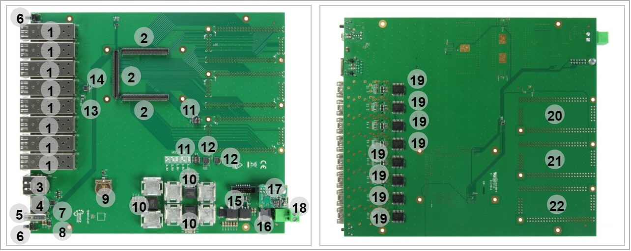
- SFP+ Connector, J4 J6 J8 J10 J13 J15 J18 J20
- Board to Board Connector (B2B), J1 J2 J3
- RJ45 Gigabit Ethernet connector, J22
- SD card connector, J16
- USB connector, J41
- Push Button, S2 S3
- SDIO port expander, U15
- Power distribution switch, U4
- Battery holder, B1
- Mag I3C power, U26 U12 U5
- Push bottun switch, S1 S4
- Buck regulator, U6 U7
- I2C EEPROM, U33
- Low voltage chanel I2C switch, U16
- Overvoltage, undervoltage, reversesupply protection controller, U13
- EMI suppression filter, U29
- JTAG interface, J12
- Power jack, J31
- 8bit IO expandor for I2C bus, U18 U25
- Pin Headers J23...26 (Not Assembled)
- Pin Headers J27-J28-J32-J36 (Not Assembled)
- Pin Headers J37...40 (Not Assembled)
Initial Delivery State
| Page properties | ||||
|---|---|---|---|---|
| ||||
Notes : Only components like EEPROM, QSPI flash and DDR3 can be initialized by default at manufacture. If there is no components which might have initial data ( possible on carrier) you must keep the table empty |
...
Overview
Content Tools