Page History
e
| Table of Contents |
|---|
Installation of Jupyter
 Example picture
The modules TEI0015 and TEI0016 offer software demonstrations of their basic functionality and
communication interface.
This manual provides a step by step guide for installing the required software and running the demos in general.
For the ease of accessibility and programmability the language Python (since version 3.5) has been chosen.
The project Jupyter provides an excellent and open source entry for beginners and professionals.
Jupyter files are called Notebooks and have the ending fileName.ipynb, this manual refers to them as demo.
The following description of steps applies in its details to computers running windows 10, for other
operation systems, the steps are in general similar.
So running and editing the Demos requires the following steps:
- Step 1 - Installation of Anaconda respectively jupyter
- Step 2 - Installation of "pyserial"
- Step 3 - Driver installation for the module
- Step 4 - Making the demos accessible for Jupyter
- Step 5 - Starting Jupyter
- Step 6 - Opening a demo
- Step 7 - Alter the comport to yours
- Step 8 - Running the demo
- Annotations
Installation of Anaconda respectively Jupyter
The simplest way to execute the demos in Jupyter is accomplished throw the installation of Anaconda.
This will install more than is needed but nearly all requirements in one step.
The Anaconda website provides detailed instructions on how to install the application, just follow this link.
If the installer offers you the installation of optional application, just skip those, they are
not needed to run the demos or edit their code.
Installation of Pyserial
At least with Anaconda installation on Windows, pyserial (python serial port support library) is not
included and has to be installed. This can be done from the Anaconda command prompt. To open the
Anaconda command prompt, just press the windows key, type Anaconda prompt and open it. Enter
conda install -c anaconda pyserial
into the command prompt an press enter. This starts the search for software dependencies of pyserial,
you are asked to confirm the installation, to proceed press Y.
The console shows a message when pyserial is installed and thereafter the console is no longer needed
and can be closed.
Driver installation for the module
The communication with a module supposes a comport, and therefore a driver is required.
When connecting the module to your computer, windows starts the Automatic driver Installation,
but often the automatic driver installation fails and the driver needs to be installed manually.
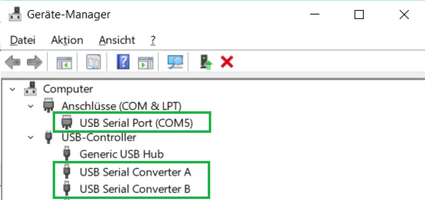
So it is best practice to connect the module, give the operation system some time, and check
afterwards in the device manager for the appearance of a "comport" and two devices labelled
"USB Serial Convert A and B".
The device manager can be opened either via a right mouse click onto the windows symbol
or by pressing the windows button and typing device manager.
When instead two devices labelled "Arrow USB Blaster" are listed under "other devices", the manual
approach has to be taken.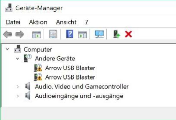
Through a right mouse click on each device, a context menu opens. Chose "Update driver" afterwords chose
"Search automatically for updated driver software", this proper driver installation changes the devices names
into USB Serial Converter A & B, in addition, also the comport is installed.
Check its number (“ComX” ) and memorize it for the later use within the demos.
In dependency to the modules firmware, the driver installation can lead to the appearance of two comports,
in this instance, the higher numbered comport is of importance.
Link to further Information and an Installation Guide for Linux
Making the demos accessible for Jupyter
The demos for a module are compressed into a zip archive and need to be extracted, to be accessible for
Jupyter. Jupyter has access to the user folder, so a convenient way is to copy the extracted demo folder
into your users folder, for example:
C:\Users\Username\distribution-folder
Starting Jupyter
To open Jupyter, press the windows key and type Jupyter, this presents "Jupyter Notebook (AnacondaX)" to you,
from which one can start Jupyter.
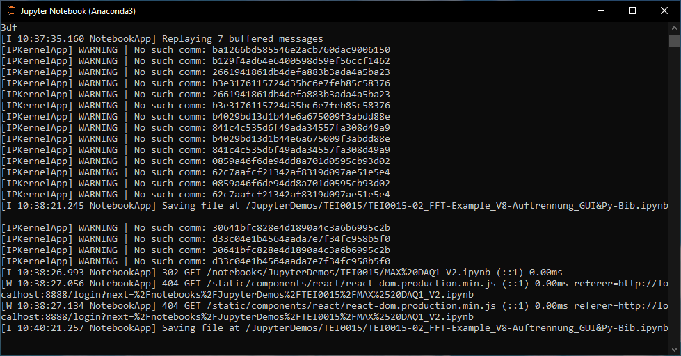
Jupyter is based on the server client structure, the server is executed in the background, and the client is a webpage
inside your default browser.
So opening it starts the server, which opens a console displaying status messages of the server.
The console must be open all the time, you want Jupyter to run. You can minimize it.
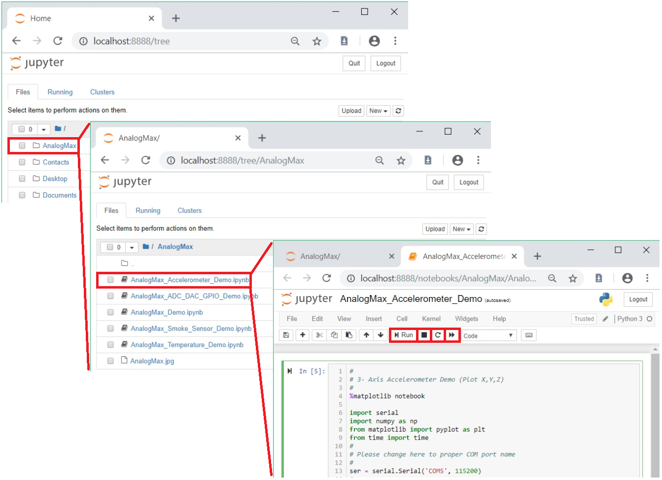
Opening a demo
To open a demo, one hat to navigate to the desired demo via the Jupyter tab. The Jupyter tab inside your browser
displays your user folder, left clicking on a folder opens it. Clicking on a demo file opens it inside its tab.
In the pictures below the steps are shown.
- Home folder / Jupyter tab
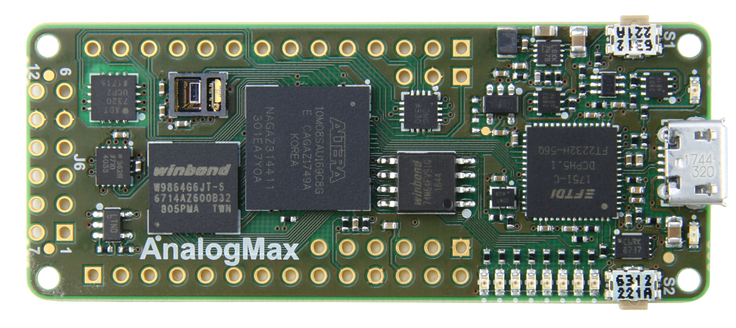
- Folder - AnalogMax
- Demo - AnalogMax_Accelerometer_Demo
Alter the comport to yours
Every demo communicates with the module by a serial communication port. This port has been assigned
a number during the driver installation. In our case it is COM5.
At the beginning of each demo is a line:
ser = serial.Serial('COM5', 115200)
Replace the comport number in red with yours and save this change by pressing "s" whilst holding the
control key (Ctrl + s).
Running the demo
A notebook consists of cells, in which its content resides. Demos so far only contain one cell, to run the demo,
the PC's focus must be upon the cell, left clicking into the cells source code focuses this cell.
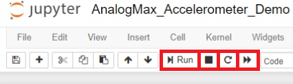
Now the demo can be run through pressing the run button,
stopped by the button with the black rectangular,
reloaded through the circular arrow and lastly
reloaded and rerun by the two arrowed button.
The notebook can be closed either by closing the tab or via File → "Close and Halt".
Often demos gather data from the module and display them in graph plots.
Annotations
- The demos are linked to Jupyter through the import and use of only the following modules:
IPython - Interacting from within the Notebook with its output / plots
ipywidgets - Interactive Widgets/GUI elements for the Jupyter Notebook - Show line numbers inside a notebook: View → Toggle Line Numbers
The Communication Interface Commands
The modules TEI0015 and TEI0016 implements a handler for executing commands. The serial interface speed
must be set to 115200 bits, commands consists of a single character in UTF-8 encoding.
Each command must be transmitted individually.
These commands apply since module revision 03.
, TEI0016 and TEI0023 implement a handler for executing commands. The serial interface speed
must be set to 115200 bits, commands consists of a single character in UTF-8 encoding.
Each command must be transmitted individually.
All commands are identical for all tree modules, except commands for setting the gain.
The modules TEI0015 and TEI0016 recognizes the following gain commands since module revision 02:
"1" Sets the pre-amplification of the ADC's input to 1
"2" Sets the pre-amplification of the ADC's input to 2
"4" Sets the pre-amplification of the ADC's input to 4
"8" Sets the pre-amplification of the ADC's input to 8
The following gain commands are recognized by all TEI0023 modules in every module revision:
"0" Deactivates the pre-amplifier
"1" Sets the pre-amplification of the ADC's input to 0.25
"2" Sets the pre-amplification of the ADC's input to 0.5
"3" "1" Sets the pre-amplification of the ADC's input to 1. Firmware dependend
"24" Sets the pre-amplification of the ADC's input to 2. Firmware dependend
"45" Sets the pre-amplification of the ADC's input to 4. Firmware dependend
"86" Sets the pre-amplification of the ADC's input to 8. Firmware dependend
"r" The ADC measure once and transmits this value8" Sets the pre-amplification of the ADC's input to 16
The modules TEI0015 and TEI0023 have an ADC with additional features since revision 02 for TEI0015 and revision 03 for TEI0023:
"S" Activates the Input Span Compression
"s" Deactivates the Input Span Compression
"H" Activates the High-Z Mode
"h" Deactivates the High-Z Mode
These commands are recognized by every module:
"t" The ADC measures 1 mega samples and saves the values into its SD-RAM
"." A single value of stored ADC measurment is transmitted
"+" 128 values of stored ADC measurements are transmitted
"*" 16 kbit values of stored ADC measurements are transmitted
"x" Instead of ADC values, the value "12345" is stored 1M times in into its SD-RAM, values are transmitted via ".", "+" and "*"
"y" Instead of ADC value, hexadecimal values, in ascending order, are generated and stored into the SD-RAM,
the values are transmitted in via "." , "+" and "*"
"z" The value "12345" is generated and direct transmitted 256 times
"?r" The module returns its ID, TEI0015 returns "1" and TEI0016 returns "2"
ADC data acquisition and Fourier transformation Demo
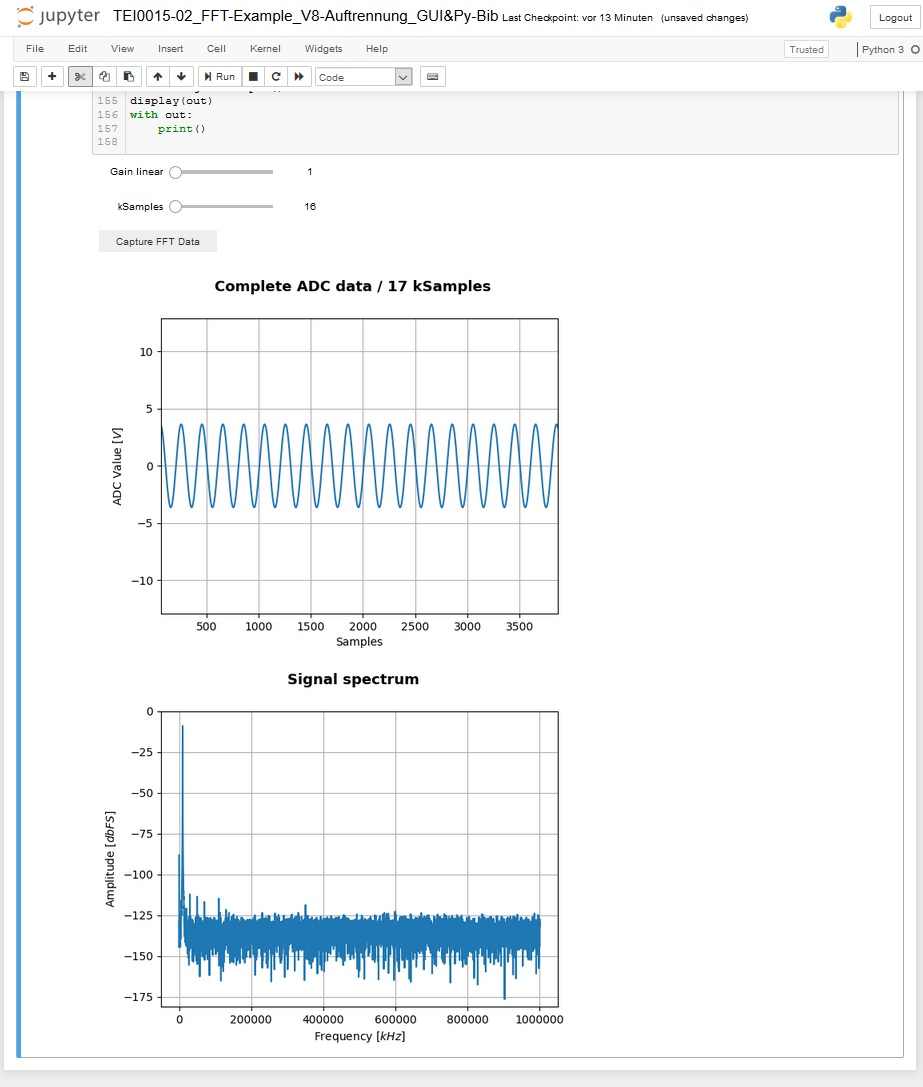
This demo works with the modules TEI0015 and TEI0016. In this example the ADC of the module measures one million samples
and stores them inside its SD-RAM. The data is collected, converted and shown as graph plot, showing its value and
time behaviour and for the second graph a Fourier transformation is performed, showing the Frequency spectrum.
The user can adjust the pre-amplification and length of the data to be processed.
In this demo the general approach on how to communicate with the module and perform high speed measurements with
the ADC are shown.
Communicating with module:
To communicate with the module, a serial comport port with a speed set to 115200 bits needs to be opened.
Commands consists of a single character in UTF-8 encoding.
It is good practice to communication with the module following these steps:
- Open a serial comport
- Clear the PCs serial comport input buffer of the opened comport
- Send the desired commands, each one in a single write operation to the comport
- Close the serial comport as soon as possible
These steps apply also for read operations.
Using the ADC for high speed consecutive measurements
The module provides a method to gather highly accurate consecutive ADC measurements in a single event.
In this mode of operation, one mega sample of ADC values are performed and stored inside the modules
SD-RAM.
The following step should be taken in this mode:
- Open a serial comport
- Send the command "1", "2", "4" or "8" for the ADC pre-amplification
- Send the command "t" to trigger the consecutive measurement
- Clear the PCs serial comport input buffer of the opened comport
- Send the command "+" or "*", the module transmits 128 or 16384 Samples of ADC values
- Read the amount of ADC values in one chunk of 128 or 16384 samples from the serial input buffer of the PC
- Repeat the reading of chunks to a maximum of 1 mega sample
- Close the comport
After a trigger event, the one mega sample of data is stored until your retrigger. So processing the data can
be done for each chunk individually or the whole one mega sample.
Information to convert the RAW ADC data into standard integer values.
Module TEI0015 - AD4003BCPZ-RL7
Resolution: 18-bit / 5 nibbles
Maximum sampling rate: 2 MSPS
Order of Values:
...
The layout of the ADC circuit is further described in the Analog Devices circuit note CN-0385.
Module TEI0016 - ADAQ7988BCCZ
Resolution: 16-bit / 4 nibbles
Maximum sampling rate: 0.5 MSPS
Order of Values:
...
The ADC measure once and transmits this value
"." A single value of stored ADC or generated measurement is transmitted
"+" 128 values of stored ADC or generated measurements are transmitted
"*" 16 kbit values of stored ADC or generated measurements are transmitted
"?" The module returns its ID:
TEI0015 with ADC AD4003 / 2 MSps returns "1"
TEI0016-0x-08-C8A with ADC ADAQ7988 / 0.5 MSps returns "2"
TEI0016-0x-08-C8B with ADC ADAQ7980 / 1 MSps returns "3"
TEI0023A with ADC AD4003 / 2 MSps returns "4"
"F" The module activates a square wave signal,
frequency = 10 kHz and amplitude is +3,3 V / ground
the signal is accessible on the pads
- D5 in normal mode and
- D6 in time inverted mode
"f" Deactivation of the square wave signalThe layout of the ADC circuit is further described in the Analog Devices circuit note CN-0393.
Overview
Content Tools