Page History
The modules TEI0015, TEI0016 and TEI0016 implements TEI0023 implement a handler for executing commands. The serial interface speed
must be set to 115200 bits, commands consists of a single single character in UTF-8 encoding.
Each command must be transmitted individually..
All commands are identical for all tree modules, except commands for setting the gain.
The modules TEI0015 and TEI0016 recognizes the following gain commands These commands apply since module revision 03.02:
"1" Sets the pre-amplification of the ADC's input to 1. Firmware dependend
"2" Sets the pre-amplification of the ADC's input to 2. Firmware dependend
"4" Sets the pre-amplification of the ADC's input to 4. Firmware dependend
"8" Sets the pre-amplification of the ADC's input to 8. Firmware dependend
"r" The ADC measure once and transmits this value
"t" The ADC measures 1 mega samples and saves the values into its SD-RAM
"." A single value of stored ADC measurment is transmitted
"+" 128 values of stored ADC measurements are transmitted
The following gain commands are recognized by all TEI0023 modules in every module revision:
"0" Deactivates the pre-amplifier
"1" Sets the pre-amplification of the ADC's input to 0.25
"2" Sets the pre-amplification of the ADC's input to 0.5
"3" Sets the pre-amplification of the ADC's input to 1
"4" Sets the pre-amplification of the ADC's input to 2
"5" Sets the pre-amplification of the ADC's input to 4
"6" Sets the pre-amplification of the ADC's input to 8
"8" Sets the pre-amplification of the ADC's input to 16
The modules TEI0015 and TEI0023 have an ADC with additional features since revision 02 for TEI0015 and revision 03 for TEI0023:
"S" Activates the Input Span Compression
"s" Deactivates the Input Span Compression
"H" Activates the High-Z Mode
"h" Deactivates the High-Z Mode
These commands are recognized by every module:
"t" The ADC measures 1 mega samples and saves the values into its SD-RAM"*" 16 kbit values of stored ADC measurements are transmitted
"x" Instead of ADC values, the value "12345" is stored 1M times in into its SD-RAM, values are transmitted via ".", "+" and "*"
"y" Instead of ADC value, hexadecimal values, in ascending order, are generated and stored into the SD-RAM,
the values are transmitted in via "." , "+" and "*"
"z" The value "12345" is generated and direct transmitted 256 times
"?r" The module returns its ID, TEI0015 returns "1" and TEI0016 returns "2"
ADC data acquisition and Fourier transformation Demo
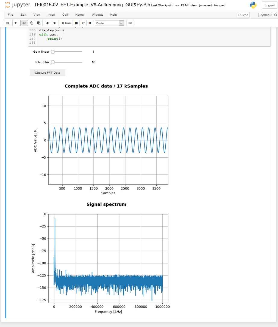
This demo works with the modules TEI0015 and TEI0016. In this example the ADC of the module measures one million samples
and stores them inside its SD-RAM. The data is collected, converted and shown as graph plot, showing its value and
time behaviour and for the second graph a Fourier transformation is performed, showing the Frequency spectrum.
The user can adjust the pre-amplification and length of the data to be processed.
In this demo the general approach on how to communicate with the module and perform high speed measurements with
the ADC are shown.
Communicating with module:
To communicate with the module, a serial comport port with a speed set to 115200 bits needs to be opened.
Commands consists of a single character in UTF-8 encoding.
It is good practice to communication with the module following these steps:
- Open a serial comport
- Clear the PCs serial comport input buffer of the opened comport
- Send the desired commands, each one in a single write operation to the comport
- Close the serial comport as soon as possible
These steps apply also for read operations.
Using the ADC for high speed consecutive measurements
The module provides a method to gather highly accurate consecutive ADC measurements in a single event.
In this mode of operation, one mega sample of ADC values are performed and stored inside the modules
SD-RAM.
The following step should be taken in this mode:
- Open a serial comport
- Send the command "1", "2", "4" or "8" for the ADC pre-amplification
- Send the command "t" to trigger the consecutive measurement
- Clear the PCs serial comport input buffer of the opened comport
- Send the command "+" or "*", the module transmits 128 or 16384 Samples of ADC values
- Read the amount of ADC values in one chunk of 128 or 16384 samples from the serial input buffer of the PC
- Repeat the reading of chunks to a maximum of 1 mega sample
- Close the comport
After a trigger event, the one mega sample of data is stored until your retrigger. So processing the data can
be done for each chunk individually or the whole one mega sample.
Information to convert the RAW ADC data into standard integer values.
Module TEI0015 - AD4003BCPZ-RL7
Resolution: 18-bit / 5 nibbles
Maximum sampling rate: 2 MSPS
Order of Values:
...
The layout of the ADC circuit is further described in the Analog Devices circuit note CN-0385.
Module TEI0016 - ADAQ7988BCCZ
Resolution: 16-bit / 4 nibbles
Maximum sampling rate: 0.5 MSPS
Order of Values:
...
The ADC measure once and transmits this value
"." A single value of stored ADC or generated measurement is transmitted
"+" 128 values of stored ADC or generated measurements are transmitted
"*" 16 kbit values of stored ADC or generated measurements are transmitted
"?" The module returns its ID:
TEI0015 with ADC AD4003 / 2 MSps returns "1"
TEI0016-0x-08-C8A with ADC ADAQ7988 / 0.5 MSps returns "2"
TEI0016-0x-08-C8B with ADC ADAQ7980 / 1 MSps returns "3"
TEI0023A with ADC AD4003 / 2 MSps returns "4"
"F" The module activates a square wave signal,
frequency = 10 kHz and amplitude is +3,3 V / ground
the signal is accessible on the pads
- D5 in normal mode and
- D6 in time inverted mode
"f" Deactivation of the square wave signalThe layout of the ADC circuit is further described in the Analog Devices circuit note CN-0393.
Overview
Content Tools