...
| Info |
|---|
Functionality of buttons, DIP switches, LEDs depends on CPLD Firmware. Following description is only for newest firmware version, which is available on the download area |
| Scroll Title |
|---|
| anchor | Figure_Overview |
|---|
| title | Board Overview |
|---|
|
| Scroll Ignore |
|---|
| scroll-pdf | true |
|---|
| scroll-office | true |
|---|
| scroll-chm | true |
|---|
| scroll-docbook | true |
|---|
| scroll-eclipsehelp | true |
|---|
| scroll-epub | true |
|---|
| scroll-html | true |
|---|
|
| draw.io Diagram |
|---|
| border | true |
|---|
| viewerToolbar | true |
|---|
| |
|---|
| fitWindow | false |
|---|
| diagramName | TEIB0006_TEI0006 |
|---|
| simpleViewer | false |
|---|
| width | 600 |
|---|
| diagramWidth | 641 |
|---|
| revision |
|---|
|
...
| Scroll Only |
|---|
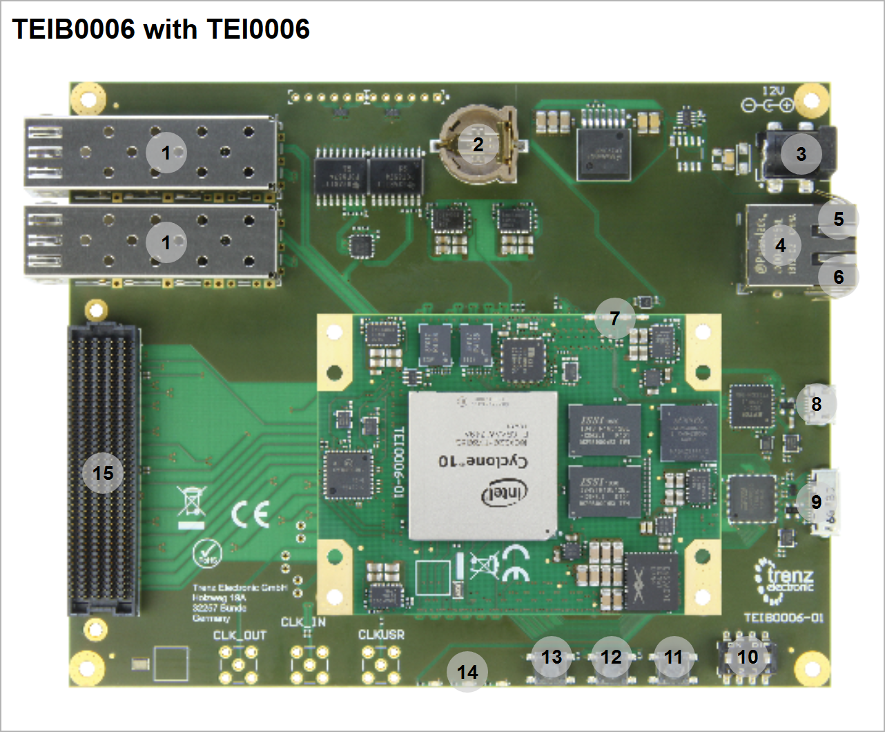 Image Removed Image Removed
|
| Number | Note |
|---|
| 1 | J1/3 - SFP+ connector |
| 2 | B1 - Battery holder CR1220J14 - CRUVI connector |
| 3 | J12 - Power Jack, 2.0mm, DC (12V power input) |
| 4 | J5 - RJ45 Ethernet Connector |
| 5 | J5 - RJ45 Ethernet Connector LED yellow (Usage: unused) |
| 6 | J5 - RJ45 Ethernet Connector LED green (Usage: unused) |
| 7 | D1 - LED red (Usage: status) red || D2 - LED green (Usage: unused) || D3 D3 - LED green (Usage: user defined) || D4 D4 - LED green (Usage: user defined) |
| 8 | J8 - USB 2.0 Micro B Receptacle |
| 9 | J13 - USB 3.0 Micro B Receptacle |
| 10 | S1 - DIP Switch for JTAG access and write protection for EEPROM U13 on TEIB0006 |
| 11 | S5 - reset button for Intel MAX 10 on TEI0006 |
| 12 | S4 - user button |
| 13 | S3 - reset button for Intel Cyclone 10 GX on TEI0006 |
| 14 | D2 - LED red (Usage: status) red || D3 - LED red (Usage: connected to user button S4) || D4 - LED green (Usage: status) |
| 15 | J6 - FMC HPC connector |
Power supply
| Page properties |
|---|
|
The input power supply must be mentioned. Add Link to overview picture with connector label.
|
...
| Label | Designator | Supply Voltage | Description |
|---|
| Overview - 3 | J12 | 12V | Single 12V power supply |
...
| Scroll Title |
|---|
| anchor | Table_DIP_1 |
|---|
| title | DIP Switches S1 |
|---|
|
| Scroll Table Layout |
|---|
| orientation | portrait |
|---|
| sortDirection | ASC |
|---|
| repeatTableHeaders | default |
|---|
| sortByColumn | 1 |
|---|
| sortEnabled | false |
|---|
| cellHighlighting | true |
|---|
|
| Overview 10 | Default | Description |
|---|
| S1-1 | ON | JTAGEN - ON = Intel Cyclone 10 GX, OFF = Intel MAX 10 | | S1-2 | OFF | WP = write-protect for EEPROM U13 on TEIB0006 - ON = read and write, OFF = only read | | S1-3 | OFF | not connected | | S1-4 | OFF | not connected |
|
...
| Scroll Title |
|---|
| anchor | Table_BUT_1 |
|---|
| title | Buttons (CPLD Firmware depended) |
|---|
|
| Scroll Table Layout |
|---|
| orientation | portrait |
|---|
| sortDirection | ASC |
|---|
| repeatTableHeaders | default |
|---|
| sortByColumn | 1 |
|---|
| sortEnabled | false |
|---|
| cellHighlighting | true |
|---|
|
| Overview 11;12;13 | Default | Description |
|---|
| S3 | High | reset button for Intel MAX Cyclone 10 GX, connected to: - nCONFIG pin (Intel MAX10Cyclone 10 GX)
- D2 - LED red (TEIB0006)
| | S4 | High | user button, connected to: - D3 - LED red (TEIB0006)
- vin_fault input of power sequencer ip in Intel MAX10
| | S5 | High | reset button for Intel Cyclone MAX 10 GX, connected to: - nCONFIG pin (Intel Cyclone 10 GXMAX10)
- D2 - LED red (TEIB0006)
|
*Note: Reset button S3 S5 is not Firmware depended |
LEDs
...
| Scroll Title |
|---|
| anchor | Table_LED |
|---|
| title | Carrier LEDs (CPLD Firmware depended) |
|---|
|
| Scroll Table Layout |
|---|
| orientation | portrait |
|---|
| sortDirection | ASC |
|---|
| repeatTableHeaders | default |
|---|
| sortByColumn | 1 |
|---|
| sortEnabled | false |
|---|
| cellHighlighting | true |
|---|
|
| Label | Designator | Color | Usage | Description |
|---|
| Overview - 5 | J5 | yellow | unused | status | connected to Ethernet phy on TEI0006not used in Firmware | | Overview - 6 | J5 | green | unused | status | connected to Ethernet phy on TEI0006not used in Firmware | | Overview - 14 | D2 | red | status | connected to reset button S5S3 | | Overview - 14 | D3 | red | --- | connected to user button S4 | | Overview - 14 | D4 | green | status | connected to VOUT (5V) from power module U28 on TEIB0006 |
*Note: LED D4 is not Firmware depended |
...
| Scroll Title |
|---|
| anchor | Table_LED |
|---|
| title | Module LEDs (CPLD Firmware depended) |
|---|
|
| Scroll Table Layout |
|---|
| orientation | portrait |
|---|
| sortDirection | ASC |
|---|
| repeatTableHeaders | default |
|---|
| sortByColumn | 1 |
|---|
| sortEnabled | false |
|---|
| cellHighlighting | true |
|---|
|
| Label | Designator | Color | Usage | Description |
|---|
| Overview - 7 | D1 | red | status | connected to nSTATUS pin from Intel Cyclone 10 GX | | Overview - 7 | D2 | greenunused | user defined | connected to GNDnfault status of power sequencer ip in Intel MAX10 | | Overview - 7 | D3 | green | user defined | connected to DATA0 pin from Intel Cyclone 10 GX | | Overview - 7 | D4 | green | user defined | connected to DATA0 pin from Intel Cyclone 10 GX |
|
...
| Label | Designator | Description |
|---|
| Overview - 8 | J8 | JTAG/UART over USB, UART Speed depends on design, normally 115200 |
...
It's recommended to use prebuilt *.pof or *.sof jic file of newest Reference Design for first test. Basic Steps:
- Power Supply over 12V power jack
- Download Reference Design
- Open Quartus Prime
- Open Quartus Programmer from top menu: Tools → Programmer
- Select from Programmer top menu: Edit → Hardware Setup
- Select via the drop down menu: Arrow-USB-Blaster [USB0] (Installation of Arrow USB Programmer Driver needed) and close the window
- Click Add File...
- Select correct *.pof or *.sof jic file and press Open
- Click Start to program the device
- Open Putty with correct COM port and Speed
- Press reset button S3
- For more details check Reference Design description
...