Page History
...
The wiki page "Installation guide for Jupyter", available via the superior page, describes how to run Jupyter, install this Notebooks dependencies, open a Notebook and execute it.
...
...
Picture of the Notebook
...
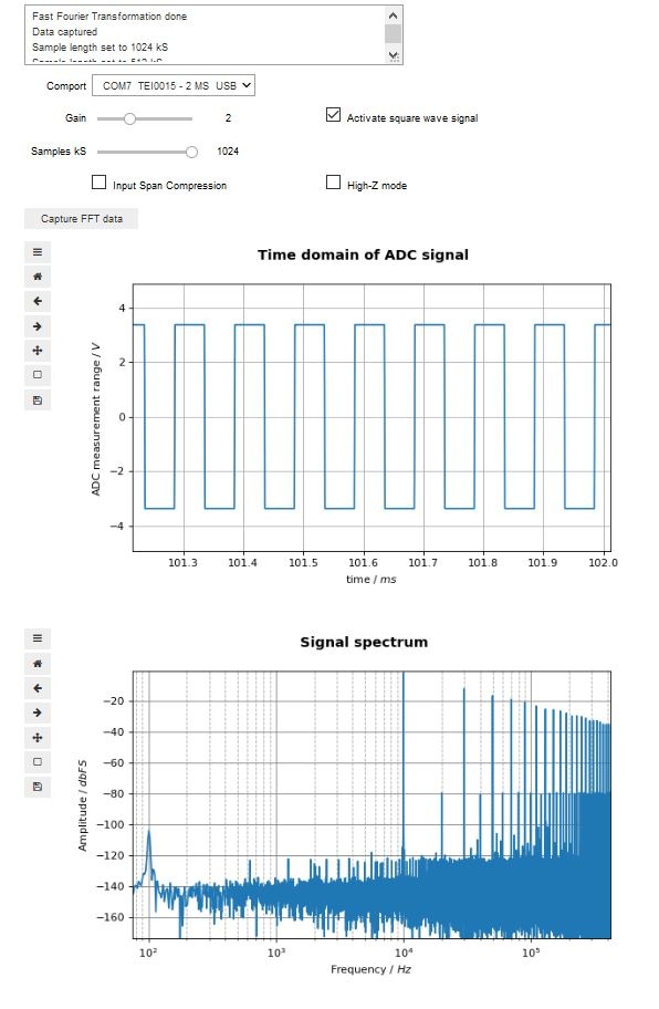
GUI elements
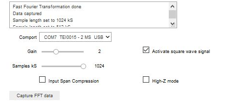
Drop-down List "Comport" :
- COM-port list for selecting a COM-port.
Listed are the port, the modules name and its USB ID
During notebook initialization, ports are scanned
...
Connecting the input signal
...
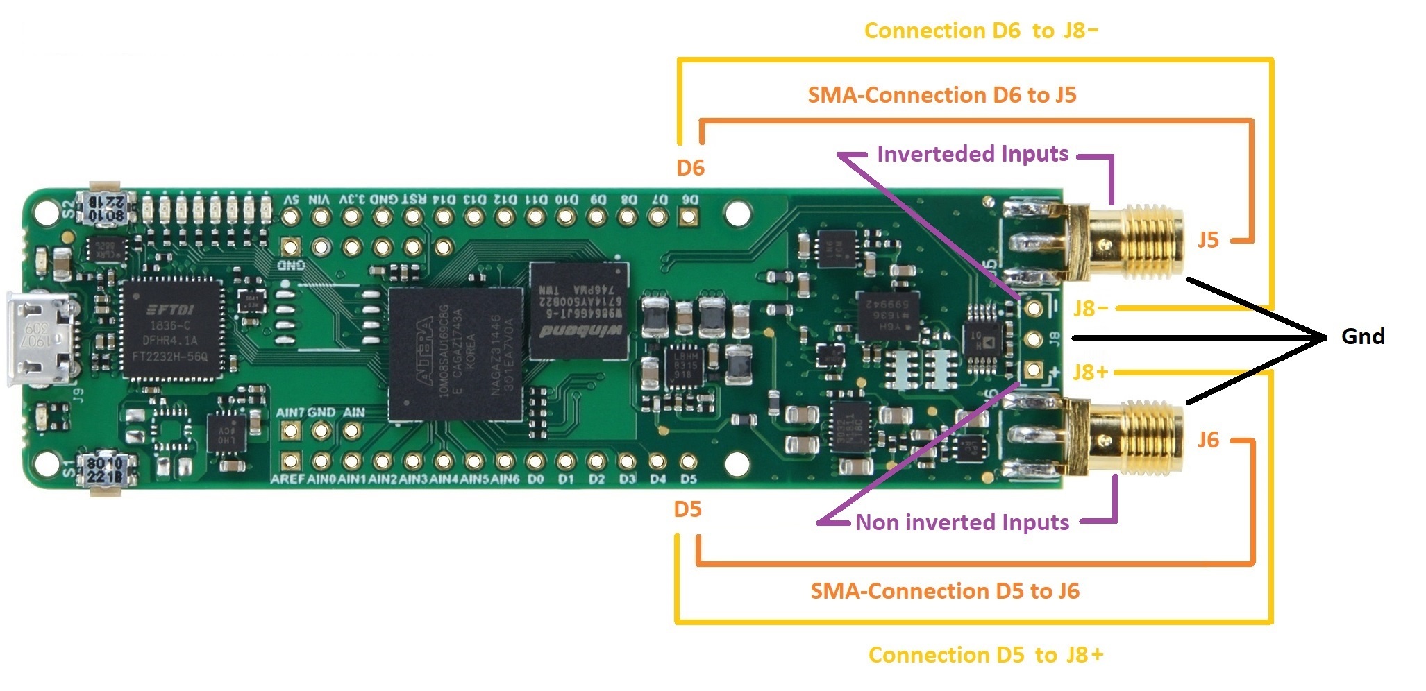
Connecting the square wave generator to the modules inputs
...
...
...
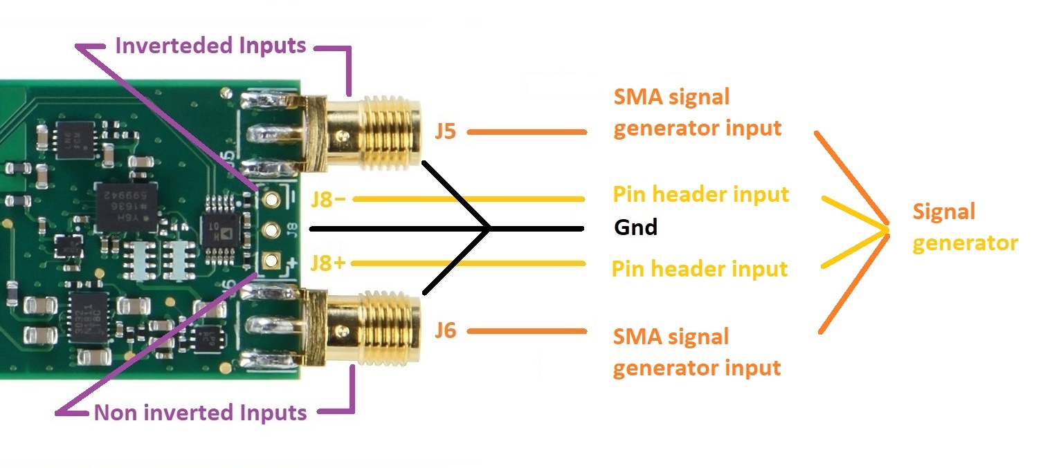
Appling a signal to the modules inputs
...
...
General programmatically interface / communication description
Communicating with module
To communicate with the module, a serial COM-port with a speed set to 115200 bits needs to be opened. Commands consists of a single character in UTF-8 encoding. It is good practice to communication with the module following these steps:
- Open a serial COM-port
- Clear the PCs serial comport input buffer of the opened comport
- Send the desired commands, each one in a single write operation to the comport
- Close the serial comport as soon as possible
These steps apply also for read operations.
Using the ADC for high speed consecutive measurements
The module provides a method to gather highly accurate consecutive ADC measurements in a single event. In this mode of operation, one mega sample of ADC values are performed and stored inside the modules SD-RAM.
The following step should be taken in this mode:
- Open a serial COM-port
- For TEI0015 and TEI0016: Send the command "1", "2", "4" or "8" for the ADC pre-amplification of 1, 2, 4, 8
For TEI0023: Send the command "1", "2", "3", "4", "5", "6" or "7" for the ADC pre-amplification of 0.25, 0.5, 1, 2, 4, 8 and 16 - Send the command "t" to trigger the consecutive measurement.
(The module always measures 1 MSample of data into its SD-RAM) - Clear the PCs serial comport input buffer of the opened comport
- Send the command "+" or "*" to the module, it then transmits 128 or 16384 Samples of ADC values
- Read the amount of ADC values in one chunk of 128 or 16384 samples from the PCs serial input buffer
(Otherwise there is a high possibility of a misalignment of nibbles) - Repeat the reading of chunks to a maximum of 1 mega sample
- Close the comport
After a trigger event, the one mega sample of data is stored until your retrigger. So processing the data can be done for each chunk individually or the whole one mega sample.
Convert the RAW ADC data into standard integer values.
Brief ADC informations - Module TEI0015 / AD4003BCPZ-RL7
Resolution: 18-bit in 5 nibbles
Maximum sampling rate: 2 MSPS
Order of Values:
...
The layout of the ADC circuit is further described in the Analog Devices circuit note CN-0385.
Brief ADC informations - Module TEI0016 / ADAQ7988 or ADAQ7980
Resolution: 16-bit in 4 nibbles
Maximum sampling rate: 0.5 MSps / 1 MSps
Order of Values:
...
The layout of the ADC circuit is further described in the Analog Devices circuit note CN-0393.
Brief ADC informations - Module TEI0023 / ADAQ4003BBCZ
Resolution: 18-bit in 5 nibbles
Maximum sampling rate: 2 MSPS
Order of Values:
...
Overview
Content Tools