Page History
| Table of Contents |
|---|
Requirements
The Data Capture Demo requires that the modules:
- FTDI chips Port B is in OPTO isolated mode
- the FPGA Intel MAX 10 is programmed with the demo specific firmware
If the module is in initial delivery condition, FTDI chip Port B is set to 245 FIFO and different Firmware,
boot requirements are not meet, so all steps on this wiki page need to be taken.
Download
Compressed folder, containing all necessary files for the demo, must de uncompressed - Download-Link
Software which needs to be installed prior to configure the module.
For changing the FTDI configuration:
- FT_Prog (Version 3.3.88.402) - Download-Link
For programming the FPGA Intel MAX 10:
- Intel - Quartus prime Lite Edition (Version 18.1) - Download-Link
- Arrow-USB-Blaster-Setup (Version 2.2) - Download-Link
- the firmware, a *.pof file as part of the compressed demo folder
The demo itself requires the installation of Visual Analog (Version 1.9.48.1) - Download Link
The compressed folder needs to be extracted, so that they can be used inside other programs.
Arrow-USB-Blaster and Quartus prime need to be installed to update the firmware,
Visual Analog for running the demo.
FTDI Port B OPTO isolated mode
Conect the module to your PC and open FT_Prog.
| Scroll Title | ||||||||||||||||||||||||||||||||
|---|---|---|---|---|---|---|---|---|---|---|---|---|---|---|---|---|---|---|---|---|---|---|---|---|---|---|---|---|---|---|---|---|
| ||||||||||||||||||||||||||||||||
|
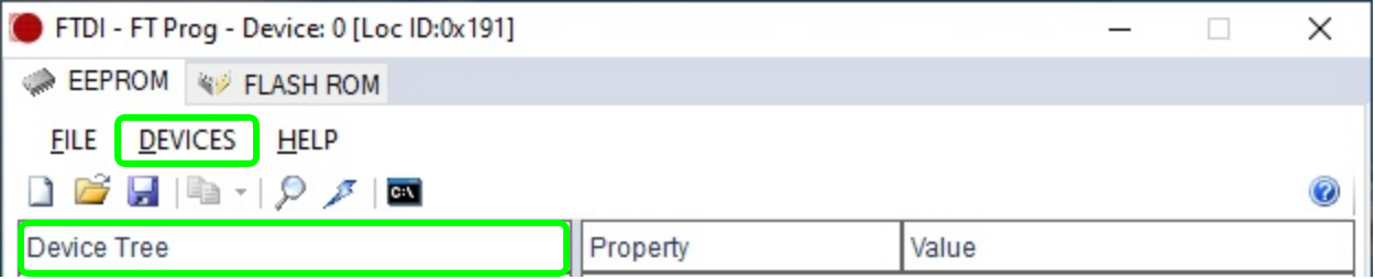
Press "Devices → Scan and parse" the modules FTDI chips configuration will be listed.
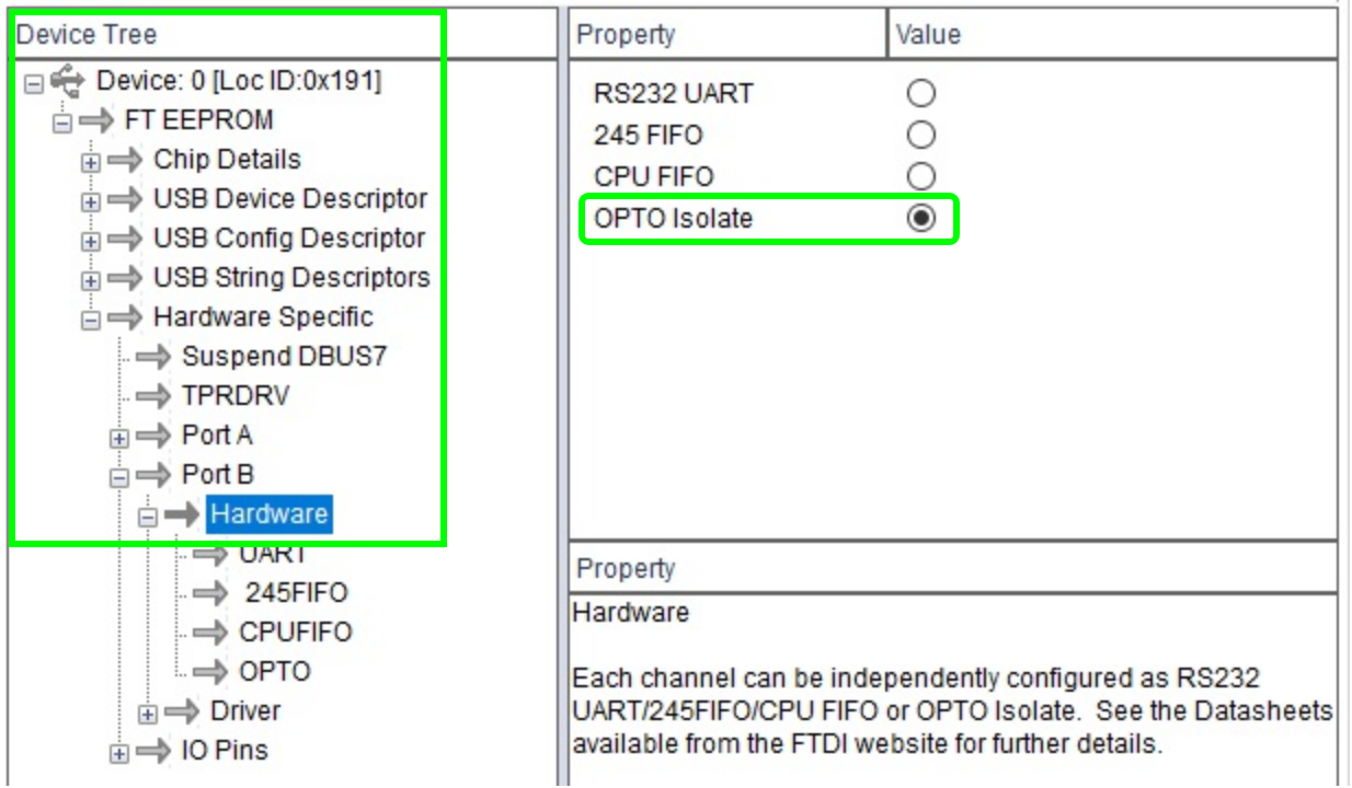
Use the "Device Tree" to navigate to "Device: ... → FT EEPROM → Hardware specific → Hardware"
and change the value to OPTO isolated.
| Scroll Title | ||||||||||||||||||||||||||||||||
|---|---|---|---|---|---|---|---|---|---|---|---|---|---|---|---|---|---|---|---|---|---|---|---|---|---|---|---|---|---|---|---|---|
| ||||||||||||||||||||||||||||||||
|
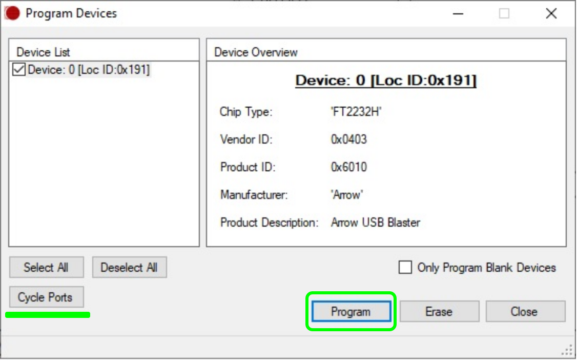
Press "Devices → Program", a new window appears, press program and after this finishes press Cycle ports.
| Scroll Title | ||||||||||||||||||||||||||||||||
|---|---|---|---|---|---|---|---|---|---|---|---|---|---|---|---|---|---|---|---|---|---|---|---|---|---|---|---|---|---|---|---|---|
| ||||||||||||||||||||||||||||||||
|
The configuration is finished, FT_Prog can be closed.
FPGA demo specific firmware
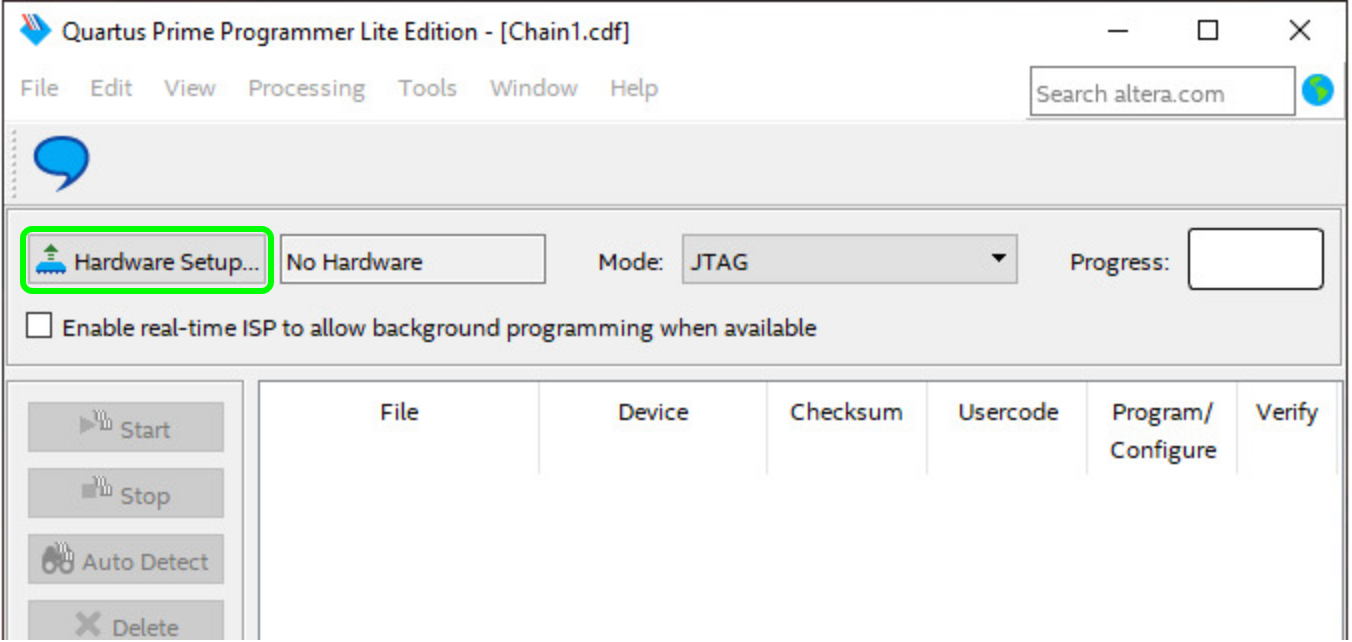
To update the firmware to the demo specific one, open Quartus prime programmer.
In the windows startmenu search for Intel FPGA 18.1. ... Lite Edition and open programmer.
In its window press "Hardware Setup..." which leads to an other new window.
| Scroll Title | ||||||||||||||||||||||||||||||||
|---|---|---|---|---|---|---|---|---|---|---|---|---|---|---|---|---|---|---|---|---|---|---|---|---|---|---|---|---|---|---|---|---|
| ||||||||||||||||||||||||||||||||
|
In it press right next to "Currently selected hardware" and select "Arrow-USB-Blaster [USBX]",
whereby the "X" in [USBX] is a placeholder.
| Scroll Title | ||||||||||||||||||||||||||||||||
|---|---|---|---|---|---|---|---|---|---|---|---|---|---|---|---|---|---|---|---|---|---|---|---|---|---|---|---|---|---|---|---|---|
| ||||||||||||||||||||||||||||||||
|
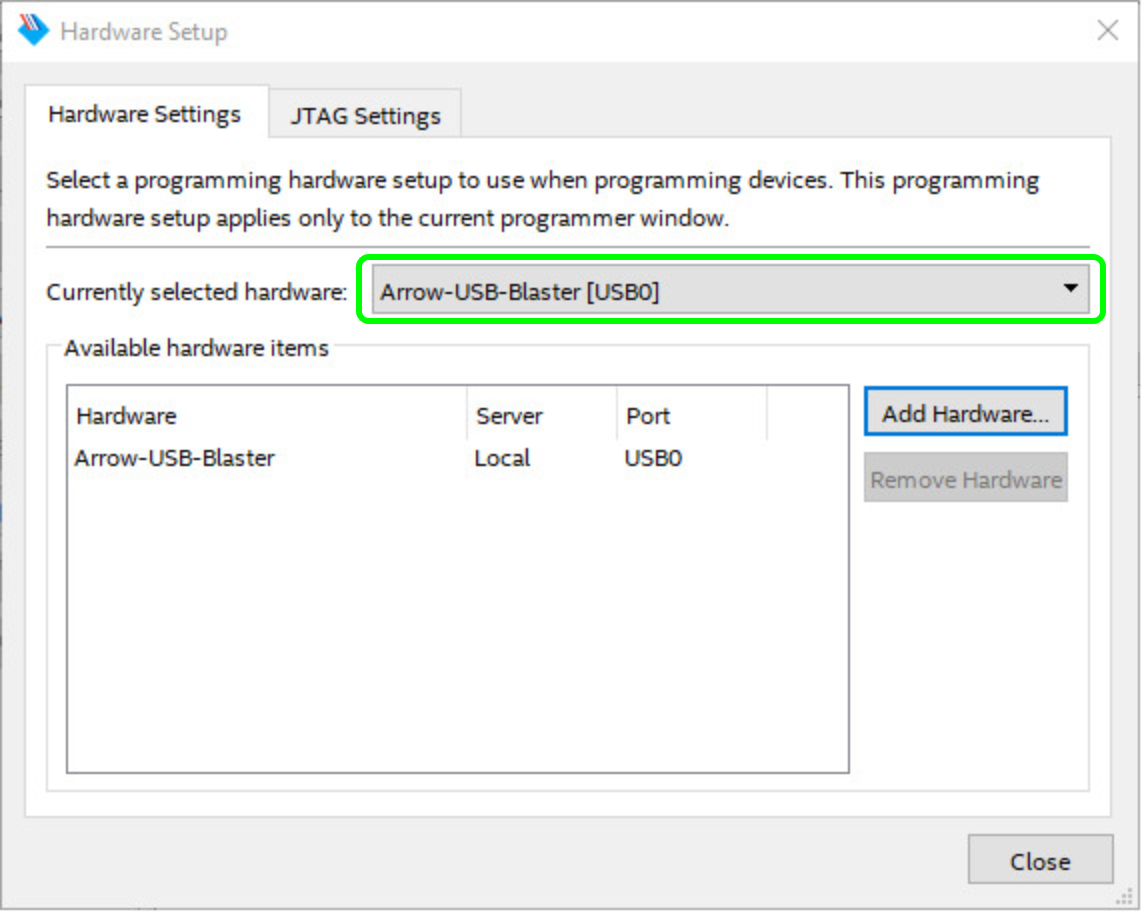
Then, press "Close" and return to the previous window.
Now the hardware is selected and through pressing Add File the downloaded *.pof firmware file can be selected.
The window layout changes slightly.
| Scroll Title | ||||||||||||||||||||||||||||||||
|---|---|---|---|---|---|---|---|---|---|---|---|---|---|---|---|---|---|---|---|---|---|---|---|---|---|---|---|---|---|---|---|---|
| ||||||||||||||||||||||||||||||||
|
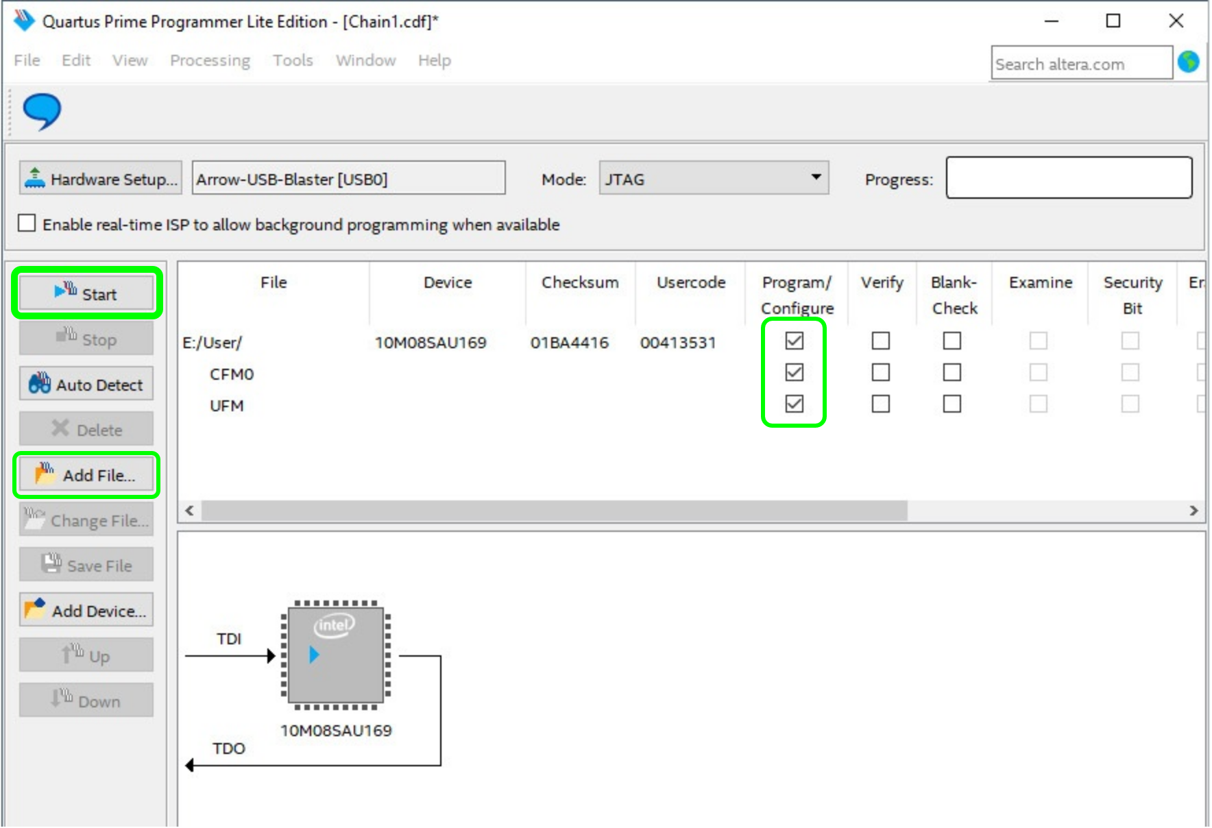
Mark the "Program/Configure" box for the selected file. The programming of the FPGA is executed, when you press the button "Start".
When the programming finishes, the Quartus Prime Programmer can be closed.
Integration with Visual Analog
- Figure out the modules COM port number
- Open the device manager, right click onto windows start menu symbol and select device manager
Open ports and identify the port used by the module, the number is here marked with an X
Scroll Title anchor Figure 1 Scroll Ignore draw.io Diagram border true viewerToolbar true fitWindow false diagramDisplayName lbox true revision 5 diagramName TEI0015_data_capture-demo_Visual-Analog_device-manager simpleViewer true width links auto tbstyle top diagramWidth 542 Scroll Only 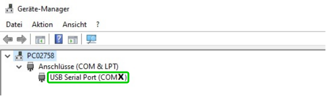
- Setup Visual Analog
Start Visual Analog and open a Blank canvas
Scroll Title anchor Figure 1 Scroll Ignore draw.io Diagram border true viewerToolbar true fitWindow false diagramDisplayName lbox true revision 2 diagramName TEI0015_data_capture-demo_Visual-Analog_open simpleViewer true width links auto tbstyle top diagramWidth 575 Scroll Only 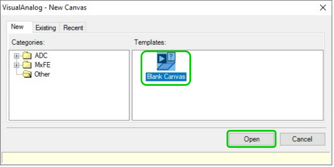
Via File → Open point to the file AnalogMAX_DAQ1_Capture.vac from the demo folder.Scroll Title anchor Figure 1 Scroll Ignore draw.io Diagram border true viewerToolbar true fitWindow false diagramDisplayName lbox true revision 2 diagramName TEI0015_data_capture-demo_Visual-Analog_blanc-canvas simpleViewer true width links auto tbstyle top diagramWidth 643 Scroll Only 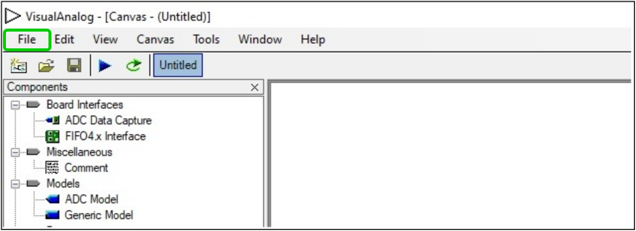
Press Tools → External Tools... to prepare the usage of adcapture.exe, in the new appearing window
Scroll Title anchor Figure 1 Scroll Ignore draw.io Diagram border true viewerToolbar true fitWindow false diagramDisplayName lbox true revision 2 diagramName TEI0015_data_capture-demo_Visual-Analog_Capture.vac simpleViewer true width 600 links auto tbstyle top diagramWidth 636 Scroll Only 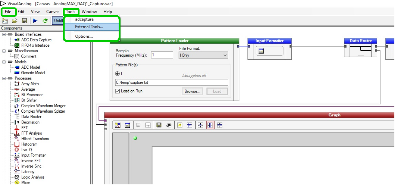
Click Add in the new opened window and insert the name "adcapture" in the Display Text.
Click Browse... and select the file "adcapture.exe" from the downloaded demo.
Into Arguments insert "COMX,115200 1024 c:\temp\capture.txt 7", where the X in COMX
is a placeholder for your comport number.To finish the setup press OK.
Scroll Title anchor Figure 1 Scroll Ignore draw.io Diagram border true viewerToolbar true fitWindow false diagramDisplayName lbox true revision 3 diagramName TEI0015_data_capture-demo_Visual-Analog_adcapture-setup simpleViewer true width links auto tbstyle top diagramWidth 445 Scroll Only 
Parameter description:
COM14 - COM port which is used for the connection.
115200 - Baud rate which is used for the connection.
1024 - Amount of K samples to read, minimum 64 and maximum is 1024.
c:\temp\capture.txt - File name and path which specifies where to storage the data.
7 - Command to adjust the gain, possible values are:
4 for a gain of 1, 5 for a gain of 2, 6 for a gain of 4 and 7 for a gain of 8
- Launch adcapture
- To run the demo, select the above inserted tool by selecting Tools → adcapture, a new window opens
The window shows the activity of the tool "adcapture", the picture below shows its state when it is finished
Scroll Title anchor Figure 1 Scroll Ignore draw.io Diagram border true viewerToolbar true fitWindow false diagramDisplayName lbox true revision 3 diagramName TEI0015_data_capture-demo_Visual-Analog_adcapture-run simpleViewer true width links auto tbstyle top diagramWidth 746 Scroll Only 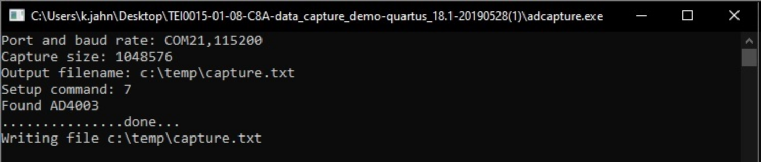
In Visual Analog, use "F5" or press Canvas → Run to update the screen
Scroll Title anchor Figure 1 Scroll Ignore draw.io Diagram border true viewerToolbar true fitWindow false diagramDisplayName lbox true revision 1 diagramName TEI0015_data_capture-demo_Visual-Analog_window-demo-run simpleViewer true width 600 links auto tbstyle top diagramWidth 1921 Scroll Only 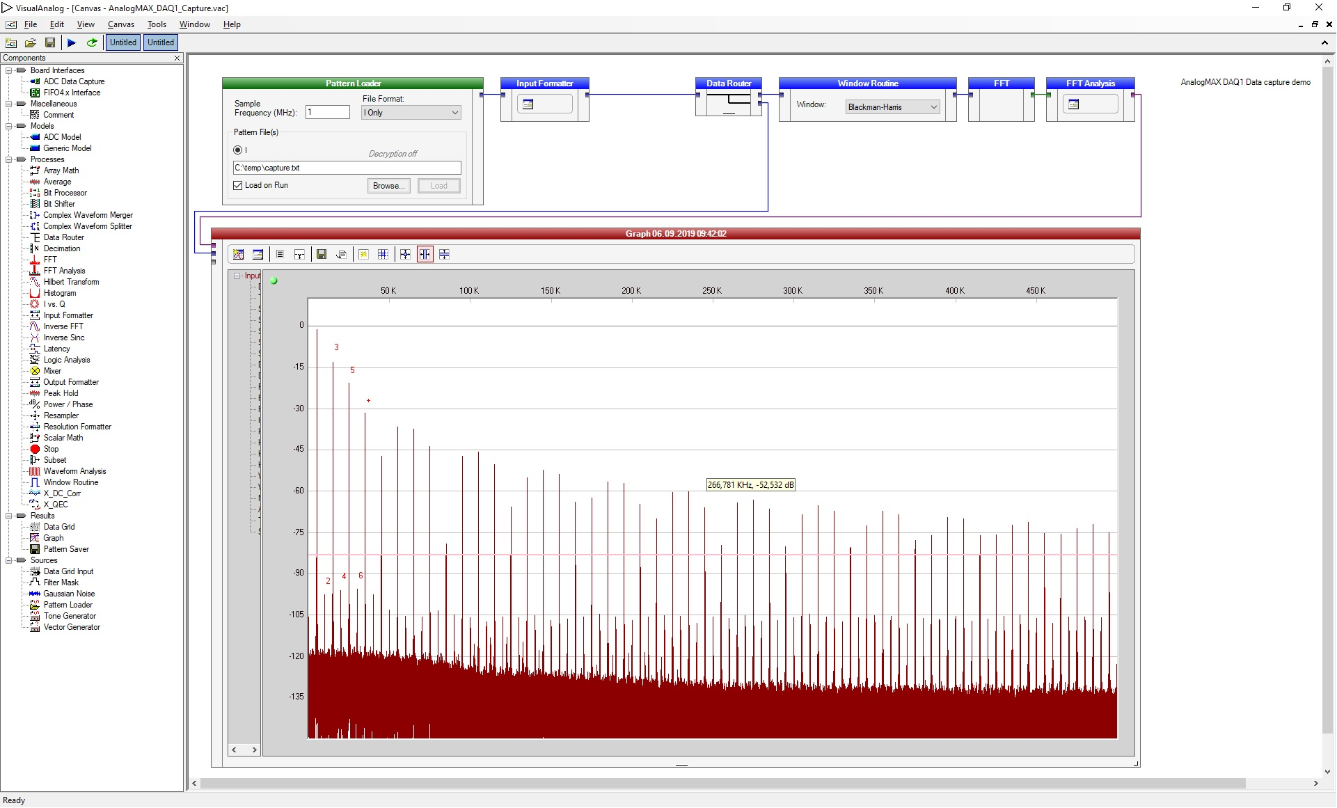
- To run the demo, select the above inserted tool by selecting Tools → adcapture, a new window opens
Quick test with a terminal program
- Figure out the correct COM port number for the AnalogMAX DAQ1 board
- Open the device manager.
Open ports and identify the port used by the AnalogMAX DAQ1 as visible in Figure 10.
- Open terminal and set the parameters (example use for putty).
- Set the connection type to Serial.
- Set the "Serial line" to your above found COM port.
- Set the "Speed" to 115200.
- Use "Open" to start the connection.
- Type following character for the appropriate usage.
- "?" to get the ID (AnalogMAX DAQ1 will return "1")
- "t" to trigger ADC capture into the memory - 1M samples.
- "." to get one ADC sample.
- "+" to get 128 samples.
- "*" to get 16*1024 samples.
Overview
Content Tools