...
| Scroll Title |
|---|
| anchor | Table_SIP_Ultra96 |
|---|
| title | Ultra96 LS Expansion information |
|---|
|
| Scroll Table Layout |
|---|
| orientation | portrait |
|---|
| sortDirection | ASC |
|---|
| repeatTableHeaders | default |
|---|
| style | |
|---|
| widths | |
|---|
| sortByColumn | 1 |
|---|
| sortEnabled | false |
|---|
| cellHighlighting | true |
|---|
|
| Schematic | Connected to | Notes |
|---|
| HD_GPIO0...7 | Level Translator HP_GPIO[0...7], U1 | GPIO | HD_GPIO8...15 | Level Translator HP_GPIO[8...15], U3 | GPIO | | MIO36-37 | Level Translator PMOD(SPI) | GPIO0-GPIO1 | | MIO38, MIO41...43 | Level Translator PMOD(SPI) | SPI | | VCC_PSAUX | Level Translator, U1-U3-U5-U6 Voltage Regulator, U2 | 1.8 V | | 5V | Voltage Regulator, U2 Jumper, J10 |
|
|
Pmod Connectors
The TEP0006 is equipped with three Pmod connectors.
| Scroll Title |
|---|
| anchor | Table_SIP_Pmod |
|---|
| title | Pmod Connectors information |
|---|
|
| Scroll Table Layout |
|---|
| orientation | portrait |
|---|
| sortDirection | ASC |
|---|
| repeatTableHeaders | default |
|---|
| style | |
|---|
| widths | |
|---|
| sortByColumn | 1 |
|---|
| sortEnabled | false |
|---|
| cellHighlighting | true |
|---|
|
|
| Schematic | Connected to | Notes |
|---|
| HD_GPIO0...7 | Level Translator HP_GPIO[0...7], U1 | GPIO |
HD_GPIO8...15 | Level Translator HP_GPIO[8...15], U3 | GPIO |
| MIO36-37 | Level Translator PMOD(SPI) | GPIO0-GPIO1 |
| MIO38, MIO41...43 | Level Translator PMOD(SPI) | SPI |
| VCC_PSAUX | Level Translator, U1-U3-U5-U6 Voltage Regulator, U2 | 1.8 V |
5V | Voltage Regulator, U2 Jumper, J10 |
MIO Pins
...
you must fill the table below with group of MIOs which are connected to a specific components or peripherals, you do not have to specify pins in B2B, Just mention which B2B is connected to MIOs. The rest is clear in the Schematic.
Example:
| Pin | Pmod 1, J1 | Pmod 2, J2 | Pmod SPI, J4 | Notes |
|---|
| 1 | PMOD_HD-GPIO0 | PMOD_HD-GPIO8 | SS |
| | 2 | PMOD_HD-GPIO1 | PMOD_HD-GPIO9 | MOSI |
| | 3 | PMOD_HD-GPIO2 | PMOD_HD-GPIO10 | MISO |
| | 4 | PMOD_HD-GPIO3 | PMOD_HD-GPIO11 | SCK |
| | 5 | GND | GND | GND |
| | 6 | 3.3 V | 3.3 V | 3.3 V |
| | 7 | PMOD_HD-GPIO4 | PMOD_HD-GPIO12 | INIT |
| | 8 | PMOD_HD-GPIO5 | PMOD_HD-GPIO13 | RESET |
| | 9 | PMOD_HD-GPIO6 | PMOD_HD-GPIO14 | Not Connected |
| | 10 | PMOD_HD-GPIO7 | PMOD_HD-GPIO15 | Not Connected |
| | 11 | GND | GND | GND |
| | 12 | 3.3 V | 3.3 V | 3.3 V |
|
|
Jumpers
...
SPI_CS , SPI_DQ0... SPI_DQ3
SPI_SCK
...
| anchor | Table_OBP_MIOs |
|---|
| title | MIOs pins |
|---|
...
| Page properties |
|---|
|
Notes : - add subsection for every component which is important for design, for example:
- Two 100 Mbit Ethernet Transciever PHY
- USB PHY
- Programmable Clock Generator
- Oscillators
- eMMCs
- RTC
- FTDI
- ...
- DIP-Switches
- Buttons
- LEDs
|
| Page properties |
|---|
|
Notes : In the on-board peripheral table "chip/Interface" must be linked to the corresponding chapter or subsection |
...
| anchor | Table_OBP |
|---|
| title | On board peripherals |
|---|
...
Quad SPI Flash Memory
| Page properties |
|---|
|
Notes : Minimum and Maximum density of quad SPI flash must be mentioned for other assembly options. |
...
| anchor | Table_OBP_SPI |
|---|
| title | Quad SPI interface MIOs and pins |
|---|
...
| anchor | Table_OBP_RTC |
|---|
| title | I2C interface MIOs and pins |
|---|
...
| anchor | Table_OBP_I2C_RTC |
|---|
| title | I2C Address for RTC |
|---|
...
| anchor | Table_OBP_EEP |
|---|
| title | I2C EEPROM interface MIOs and pins |
|---|
...
| anchor | Table_OBP_I2C_EEPROM |
|---|
| title | I2C address for EEPROM |
|---|
...
LEDs
...
| anchor | Table_OBP_LED |
|---|
| title | On-board LEDs |
|---|
...
DDR3 SDRAM
| Page properties |
|---|
|
Notes : Minimum and Maximum density of DDR3 SDRAM must be mentioned for other assembly options. (pay attention to supported address length for DDR3) |
The TE???? SoM has ??? GByte volatile DDR3 SDRAM IC for storing user application code and data.
- Part number:
- Supply voltage:
- Speed:
- NOR Flash
- Temperature:
...
| Scroll Title |
|---|
| anchor | Table_OBPSIP_ETHPmod |
|---|
| title | Ethernet PHY to Zynq SoC connectionsPmod Connectors information |
|---|
|
| Scroll Table Layout |
|---|
| orientation | portrait |
|---|
| sortDirection | ASC |
|---|
| repeatTableHeaders | default |
|---|
| style | |
|---|
| widths | |
|---|
| sortByColumn | 1 |
|---|
| sortEnabled | false |
|---|
| cellHighlighting | true |
|---|
|
BankSignal NameETH1ETH2| Signal Description | |
Clock Sources
...
| anchor | Table_OBP_CLK |
|---|
| title | Osillators |
|---|
...
Power and Power-On Sequence
...
In 'Power and Power-on Sequence' section there are three important digrams which must be drawn:
- Power on-sequence
- Power distribution
- Voltage monitoring circuit
| Note |
|---|
For more information regarding how to draw diagram, Please refer to "Diagram Drawing Guidline" . |
| J6 |
| HD_GPIO_15 VCC_PSAUX |
| | J7 |
| HD_GPIO_15 VCC_PSAUX |
| | J10 | Voltage select | SDA 5 V, 3.3 V | SDA can be either 5 V or 3.3 V |
|
On-board Peripherals
| Page properties |
|---|
|
Notes : - add subsection for every component which is important for design, for example:
- Two 100 Mbit Ethernet Transciever PHY
- USB PHY
- Programmable Clock Generator
- Oscillators
- eMMCs
- RTC
- FTDI
- ...
- DIP-Switches
- Buttons
- LEDs
|
| Page properties |
|---|
|
Notes : In the on-board peripheral table "chip/Interface" must be linked to the corresponding chapter or subsection |
Power Supply
Power supply with minimum current capability of xx A for system startup is recommended.
...
| Scroll Title |
|---|
| anchor | Table_PWR_PCOBP |
|---|
| title | Power ConsumptionOn board peripherals |
|---|
|
| Scroll Table Layout |
|---|
| orientation | portrait |
|---|
| sortDirection | ASC |
|---|
| repeatTableHeaders | default | style | widths |
|---|
| sortByColumn | 1 |
|---|
| sortEnabled | false |
|---|
| cellHighlighting | true |
|---|
|
|
| Power Input Pin | Typical Current |
|---|
| VIN | TBD* |
* TBD - To Be Determined
...
| | style | |
|---|
| widths | |
|---|
| sortByColumn | 1 |
|---|
| sortEnabled | false |
|---|
| cellHighlighting | true |
|---|
|
| Chip/Interface | Designator | Notes |
|---|
| -- | -- | -- |
|
Power and Power-On Sequence
| Page properties |
|---|
|
In 'Power and Power-on Sequence' section there are three important digrams which must be drawn: - Power on-sequence
- Power distribution
- Voltage monitoring circuit
|
Power Supply
Power supply with minimum current capability of 1 A for system startup is recommended.
Power Consumption
| Scroll Title |
|---|
| anchor | FigureTable_PWR_PDPC |
|---|
| title | Power DistributionConsumption |
|---|
|
| ignoredrawioborderfalseviewerToolbartruefitWindowfalsediagramDisplayNamelbox | true | revision |
|---|
| diagramName | TEP0006_PWR_PD |
|---|
simpleViewer | widthlinksauto | | tbstyle | hidden |
|---|
| diagramWidth | 641 |
|---|
| Scroll Only |
|---|
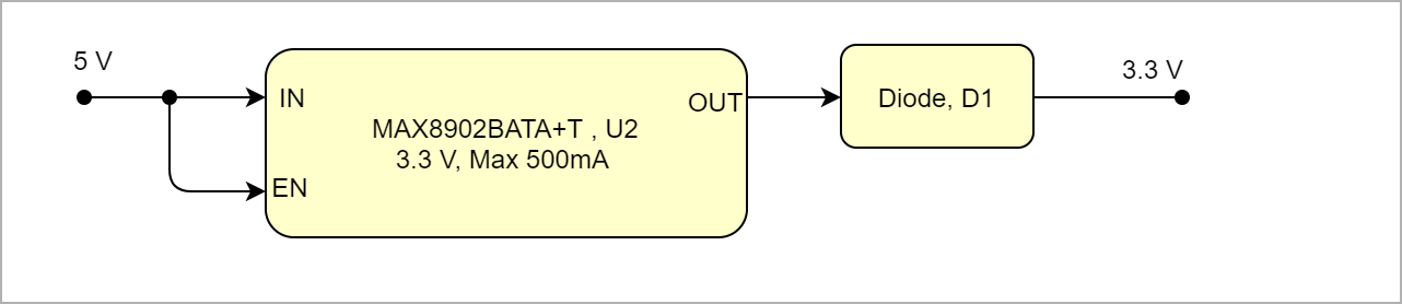 Image Removed Image Removed
|
...
| Power Input Pin | Typical Current |
|---|
| VIN | TBD* |
|
* TBD - To Be Determined
Power Distribution Dependencies
| Scroll Title |
|---|
| anchor | Figure_PWR_PSPD |
|---|
| title | Power SequencyDistribution |
|---|
|
| Scroll Ignore |
|---|
Create DrawIO object here: Attention if you copy from other page, objects are only linked. |
| Scroll Only |
|---|
image link to the generate DrawIO PNG file of this page. This is a workaround until scroll pdf export bug is fixed |
|
Power Rails
...
| anchor | Table_PWR_PR |
|---|
| title | Module power rails. |
|---|
...
B2B Connector
JM1 Pin
...
B2B Connector
JM2 Pin
...
B2B Connector
JM3 Pin
...
| draw.io Diagram |
|---|
| border | false |
|---|
| viewerToolbar | true |
|---|
| |
|---|
| fitWindow | false |
|---|
| diagramDisplayName | |
|---|
| lbox | true |
|---|
| revision | 1 |
|---|
| diagramName | TEP0006_PWR_PD |
|---|
| simpleViewer | false |
|---|
| width | |
|---|
| links | auto |
|---|
| tbstyle | hidden |
|---|
| diagramWidth | 641 |
|---|
|
|
| Scroll Only |
|---|
Image Added |
|
Power-On Sequence
| Scroll Title |
|---|
| anchor | Figure_PWR_PS |
|---|
| title | Power Sequency |
|---|
|
| Scroll Ignore |
|---|
Create DrawIO object here: Attention if you copy from other page, objects are only linked. |
| Scroll Only |
|---|
image link to the generate DrawIO PNG file of this page. This is a workaround until scroll pdf export bug is fixed |
|
Power Rails
...
| Scroll Title |
|---|
| anchor | Table_PWR_BVPR |
|---|
| title | Zynq SoC bank voltagesModule power rails. |
|---|
|
| Scroll Table Layout |
|---|
| orientation | portrait |
|---|
| sortDirection | ASC |
|---|
| repeatTableHeaders | default |
|---|
| style | |
|---|
| widths | |
|---|
| sortByColumn | 1 |
|---|
| sortEnabled | false |
|---|
| cellHighlighting | true |
|---|
|
| Power Rail Name | B2B Connector JM1 Pin | B2B Connector JM2 Pin | B2B Connector JM3 Pin | Direction |
|---|
| Schematic Name | Voltage
|
Technical Specifications
Absolute Maximum Ratings
| Scroll Title |
|---|
| anchor | Table_TS_AMR |
|---|
| title | PS absolute maximum ratings |
|---|
|
| Scroll Table Layout |
|---|
| orientation | portrait |
|---|
| sortDirection | ASC |
|---|
| repeatTableHeaders | default |
|---|
| style | |
|---|
| widths | |
|---|
| sortByColumn | 1 |
|---|
| sortEnabled | false |
|---|
| cellHighlighting | true |
|---|
|
| Symbols | Description | Min | Max | Unit |
|---|
| Vin | Input Supply Voltage | 1.7 | 5.5 | V | | T_STG | Storage Temperature | -55 | 150 | °C |
|
...
| Scroll Title |
|---|
| anchor | Table_RH_HRH |
|---|
| title | Hardware Revision History |
|---|
|
| Scroll Table Layout |
|---|
| orientation | portrait |
|---|
| sortDirection | ASC |
|---|
| repeatTableHeaders | default |
|---|
| style | |
|---|
| widths | |
|---|
| sortByColumn | 1 |
|---|
| sortEnabled | false |
|---|
| cellHighlighting | true |
|---|
|
| Date | Revision | Changes | Documentation Link |
|---|
| 2019-07-19 | REV0101 | Initial Release | REV01 |
|
Hardware revision number can be found on the PCB board together with the module model number separated by the dash.
...
| Scroll Title |
|---|
| anchor | Table_RH_DCH |
|---|
| title | Document change history. |
|---|
|
| Scroll Table Layout |
|---|
| orientation | portrait |
|---|
| sortDirection | ASC |
|---|
| repeatTableHeaders | default |
|---|
| style | |
|---|
| widths | |
|---|
| sortByColumn | 1 |
|---|
| sortEnabled | false |
|---|
| cellHighlighting | true |
|---|
|
| Date | Revision | Contributor | Description |
|---|
| Page info |
|---|
| infoType | Modified date |
|---|
| dateFormat | yyyy-MM-dd |
|---|
| type | Flat |
|---|
|
| | Page info |
|---|
| infoType | Current version |
|---|
| prefix | v. |
|---|
| type | Flat |
|---|
| showVersions | false |
|---|
|
| | Page info |
|---|
| infoType | Modified by |
|---|
| type | Flat |
|---|
| showVersions | false |
|---|
|
| | -- | all | | Page info |
|---|
| infoType | Modified users |
|---|
| type | Flat |
|---|
| showVersions | false |
|---|
|
| |
|
...