Connecting Ethernet PHY via RMII seems like the way to go as there are less wires and less clocks from the PHY.
So did I think.. until I had this on my desk (Artix A200T fresh from oven):

Starting Vivado, click click click.. Exporting to SDK, click...
Starting LwIP based Echo Server. No Echo. No nothing.
Enabling all possible software debug settings..
Nothing.. Echo server starts and nothing after that.
Stepping back to simpler test, starting Xilinx peripheral test that does PHY loop-back. Connecting Artix to PC using USB Ethernet Adapter. Starting peripheral test. Link goes down. And does not come back. Connecting DSO to RJ45 to SMA break out board and what I see?
Continuous MLT-3 encoded transmit data-streams with no gaps alternating with about 2 seconds interval on RX and TX pairs!
Consulting TLK106 datasheet: MII loopback is available in MII mode.
So?
Consulting TLK106 datasheet again: MII loopback is available in MII mode.
MII or RMII? That is the question. I have read this before but I assumed that MII refers to MII or RMII..
Changing MII loopback enable code to PCS loopback. Peripheral test still does not complete. Do we transmit something at all? So the network adapter properties dialog has never displayed any packets form Artix. Ever.
I mod one of Xilinx examples (the ping requester) to send one packet in eternal loop. Starting the app - as soon as I do, windows starts sending megabytes per second. I press halt in debugger. Windows stop sending packets. All the time the properties page shows 0 packets received.
We need Hard Debug. I mark MII pins from the RMII to MII wrapper for debugging. In Vivado analyzer I see MAC addresses in the MII RX Data bus, hence the packets do get into FPGA and do get converted from RMII to MII also. So where is the problem?
More reading, this time Ethernet Lite user guide. If packets are MII bus, and if they are at all valid (even if FCS is missing etc) then at least some bytes should be visible in the RX ping-pong buffers, right?
I switch to the XMD console in the SDK:
mrd 0x40E017FC
reads as 1, valid packet in buffer?
Lets take out network cable, and reset this bit, now it stays 0. Cable back, reading again. And again the buffer valid bit goes 1.
So why did LwIP never see any incoming packets?
I do some single stepping, and finally add one break-point at "detect ARP". Run.. and break hit.
ARP packets come and are decoded as well? So this thing must actually work? I check my own PC's IP address and adjust the local IP for the echo responder code.
ping!
< 1 ms
It does work.
So why did take so long to make it work? Maybe because I was looking at existing reference designs for too long. Digilent Nexys4 has RMII PHY but I was not able to find any reference designs at Digilent website. Then as second option there is Artix based board from Avnet with RMII PHY, but it has only been launched and the support materials are not yet online. I found also one Lattice XO2 based board that has RMII PHY and promises "source code" but in the install archive are only JEDEC files. So all my search for any FPGA example code for RMII PYH's ended up in void.
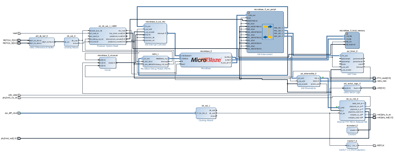
The Block Diagram of the System is bit more complicated as it should be: the CLKOUT block is small IP Core that sends a global clock to IO buffer with no phase delay using DDR I/O FlipFlop. This clock has exactly same phase as the TXD outputs to PHY. This output was only used for measurements, it is not wired to the PHY ref clock at all.
Clocking is also too complicated, during debugging I derived the PHY clock from System Clock, and System Clock from MGT Clock. Of course there was no need for this...
Overview
Content Tools