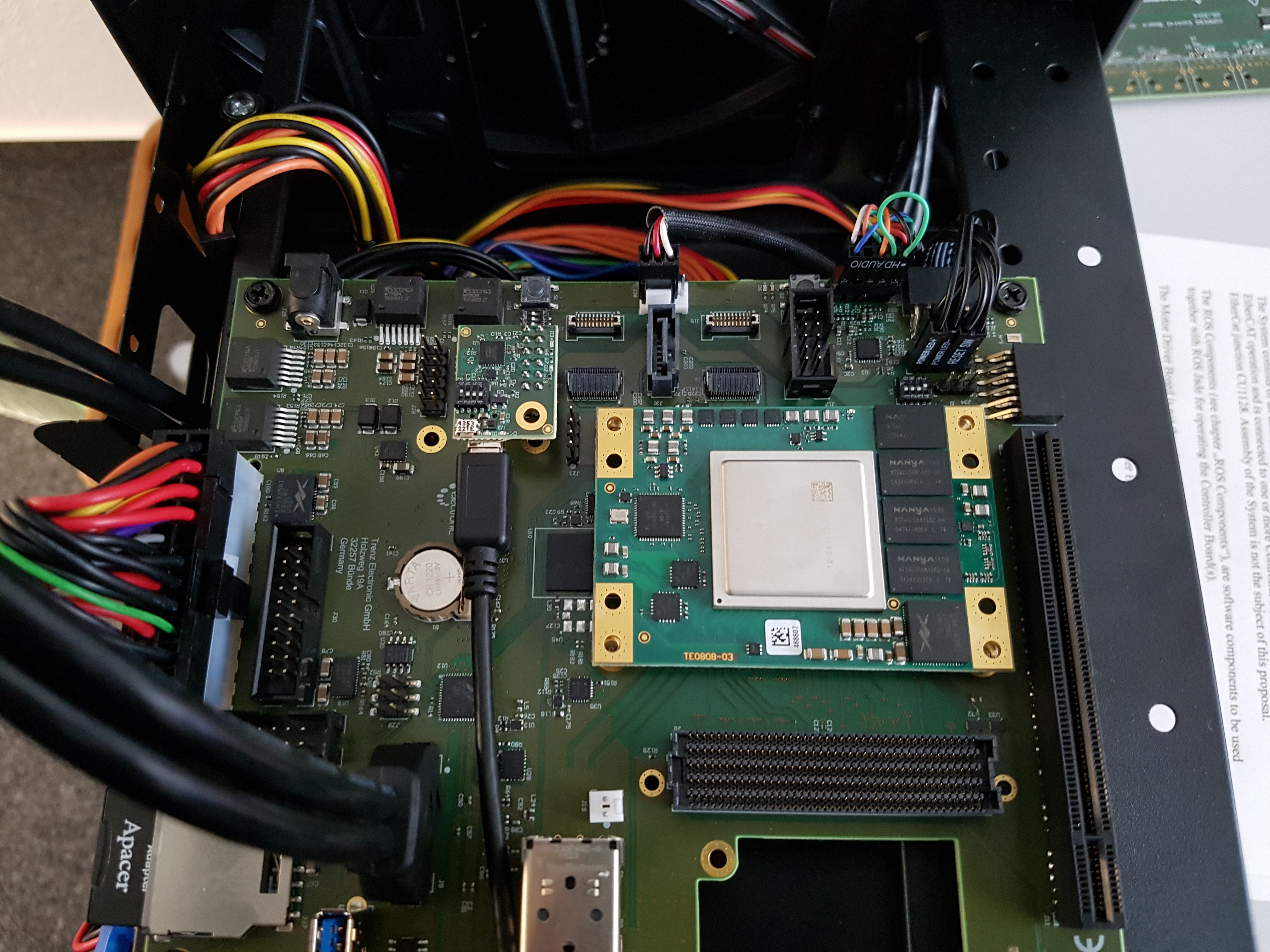
This Trenz Electronic Starter Kit consists of a TE0803 module on a TEBF0808 base board in Mini-ITX Enclosure. See shop link for detailed content.
Wiki Links
TE0803 UltraSOM+ - Wiki with TRM, reference projects, application notes and more
TE0790-XMOD FTDI JTAG Adapter - Wiki with settings and configurations
Vivado/SDK/SDSoC - Short instructions for Vivado, SDK, SDSoC
Project Delivery - General descriptions of reference designs and content
Download Links
TE0803 Download Area - contains various reference designs, schematics, hardware designs, 3D models and more
TEBF0808 Download Area - contains schematics, hardware designs, 3D models and more
TE0790-XMOD Download Area - contains firmware with projects, schematics, hardware designs, 3D models and more
TE Master Pinout - Excel Sheet as Pinout-Viewer and XDC-Generator
Shop Links
Shop TE0803-Starter-Kit - contains prices, order number, content...
Xilinx Software and Driver
Vivado Design Suite - Xilinx Design Software with JTAG drivers and documentation. Vivado Webpack XCZU3CG/EG support will be available from Version 2017.1 .
Xilinx Download Area - All Xilinx Software, Device Models and Libraries
Important Notes
Do not change XMOD DIP-Switch settings on TEBF0808. Do not swap the XMOD adapters the one marked with green dot must be closer to the SoM
ES devices are not included in all Vivado versions, for ES1 only:
activate beta device see: FAQ - How can I activate beta devices?
For all Starter Kit's shipped before 2017-06-21:
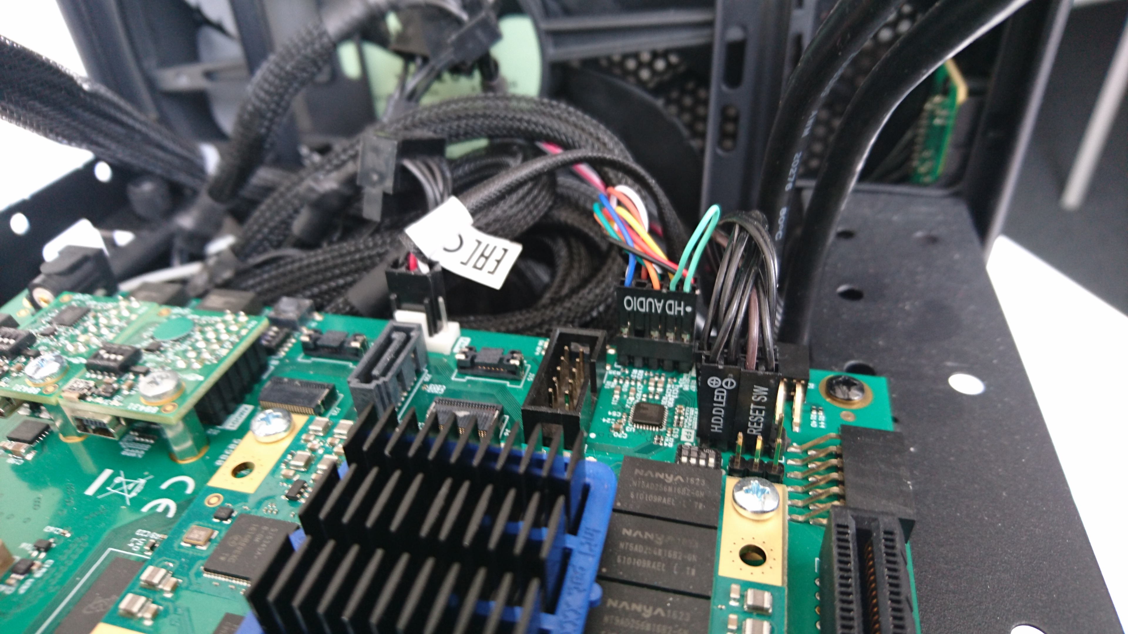
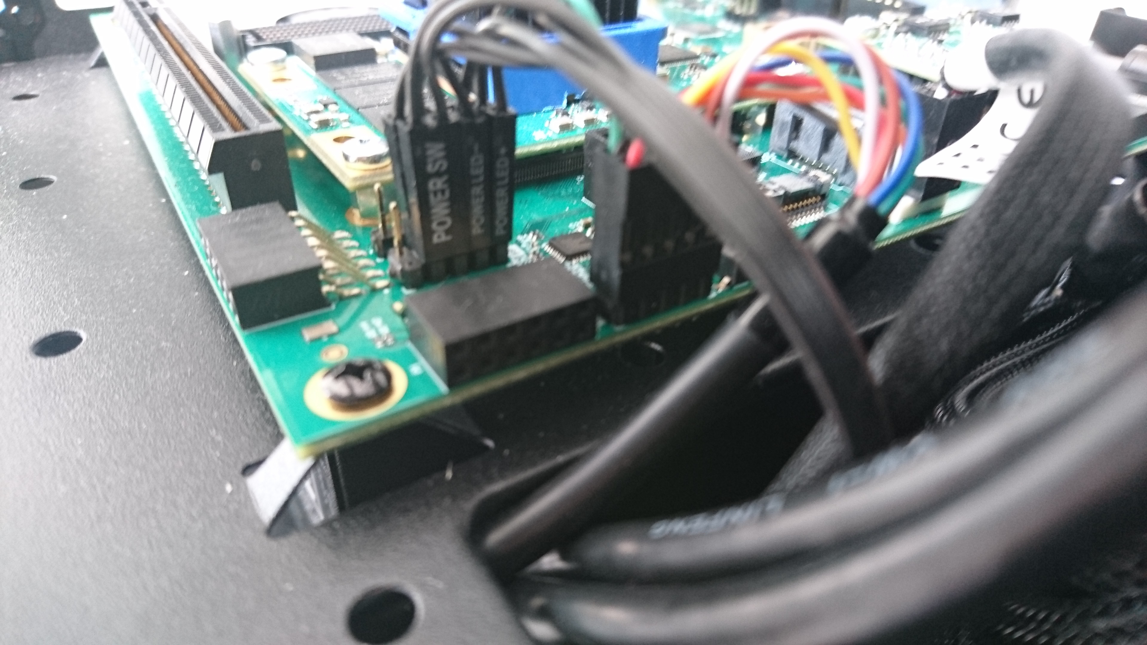
Enclosure Power and HD LED was swapped on connector. See "Enclosure Power Button, Reset Button, HDD LEDand Power LED" section for correct connection.
Getting Started
Starter Kit is shipped with prebuilt Linux Example on SD. Newest version and sources are available on our download area: TE0803 Reference Designs
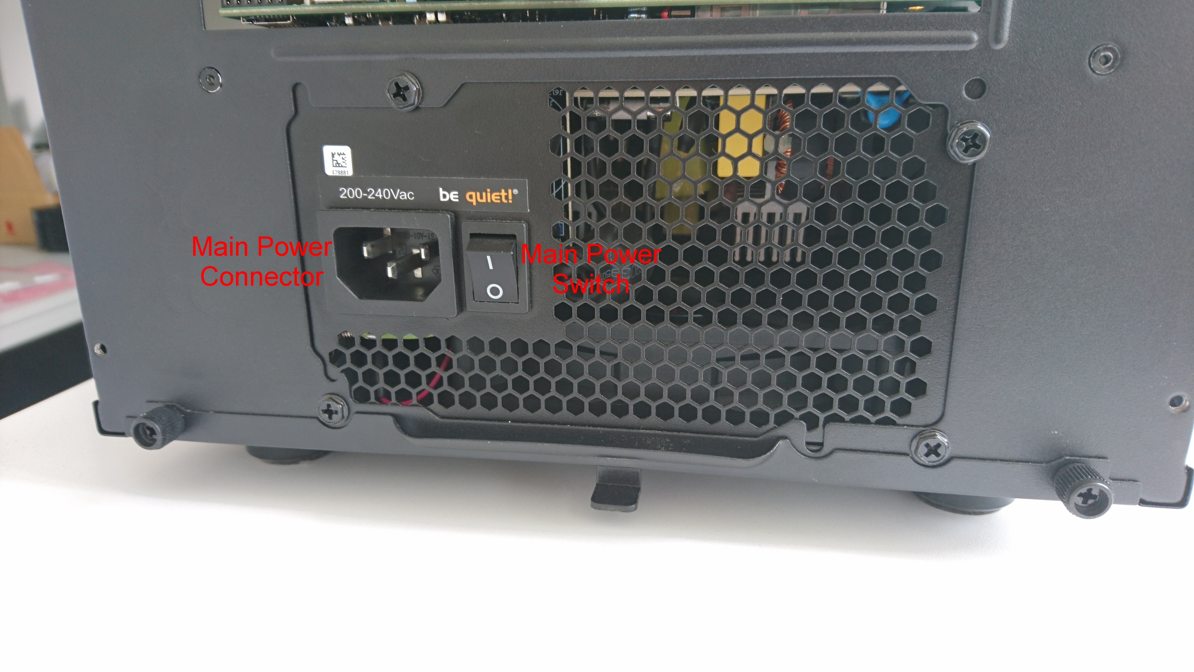
Connect main power and set power switch to on. See Main Power Enclosure Location
- Connect mini USB cable from XMOD with green dot to host PC. See XMODs Connection
- Insert SD-Card with pre-loaded content into SD-Card slot.
- Open Serial Console:
- COM Port: for correct number see device manager
- Speed:115200
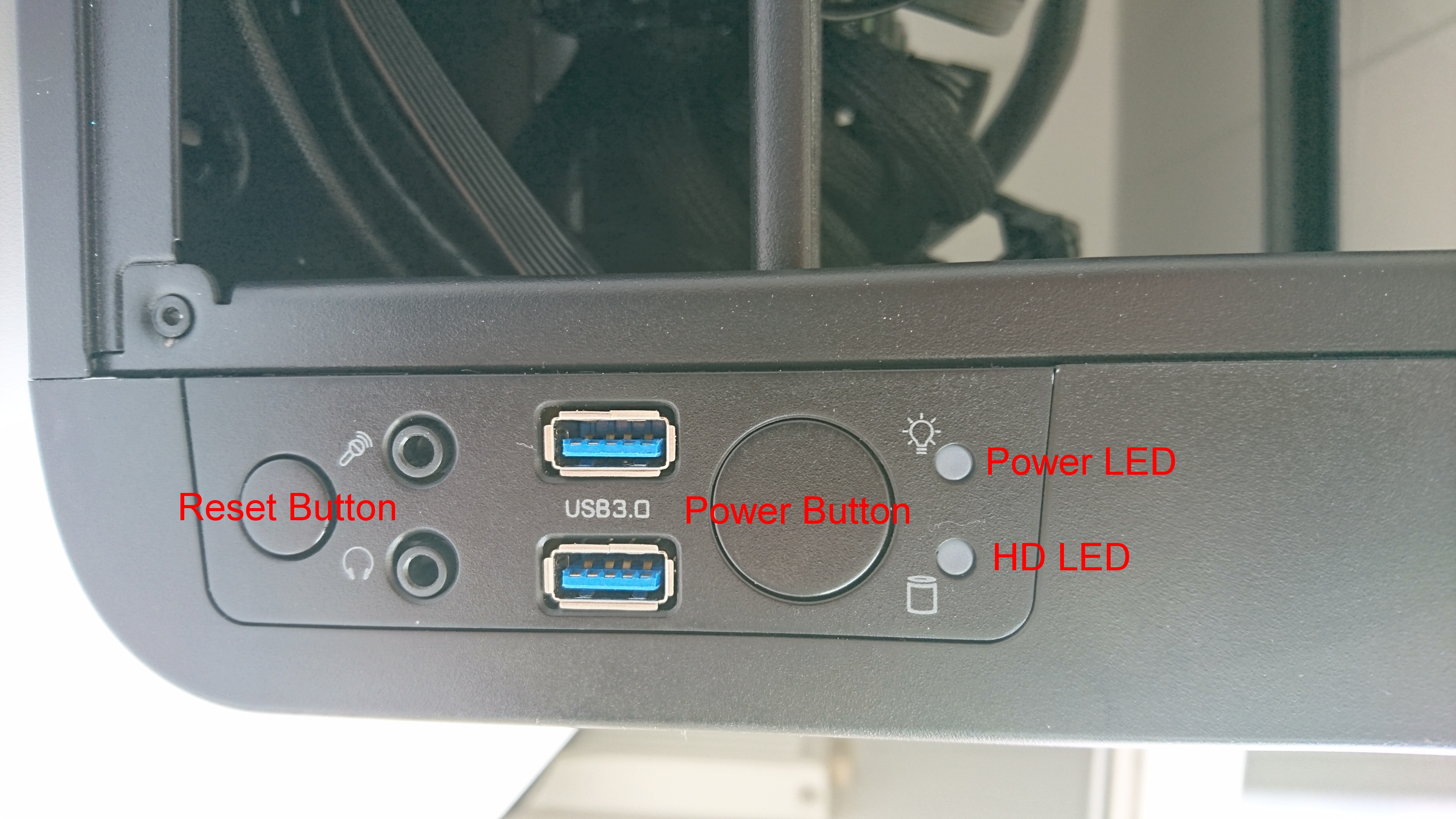
- Press the Power on button on the enclosure. See Power Button, Reset Button, HDD LED and Power LED Enclosure Location
- Linux login:
- User Name:root
- Password:root
Starter Kit Basic
Main Power Enclosure Location
Power Button , Reset Button, HDD LED and Power LED Enclosure Location
Default DIP Switch Settings
Do not change XMOD DIP-Switch settings on TEBF0808. Do not swap the XMOD adapters the one marked with green dot must be closer to the SoM
| TEBF0808 | TE0790-02 (with green dot) | TE0790-02L | |||||||||||||||||||||||||||||||||||||||||
|---|---|---|---|---|---|---|---|---|---|---|---|---|---|---|---|---|---|---|---|---|---|---|---|---|---|---|---|---|---|---|---|---|---|---|---|---|---|---|---|---|---|---|---|
|
|
|
| ||||||||||||||||||||||||||||||||||||||||
Note: with CPLD Firmware REV06 or newer, S4.4 can be set to OFF, to save power, if Starter Kit is powered off with Power Button.
For more information, see:TEBF0808, TEBF0808 Master CPLD and TEBF0808 Slave CPLD.
Starter Kit Status
- Section is currently not complete -
Main Power Switch is OFF
No Power on Starter Kit.
Identification: FANs do not work, all LEDs are off.
Main Power Switch is ON and Power Button is not pressed
Only some basics on TEBF0808 are powered on. This mode is used for CPLDs Firmware updates.
Identification: FANs do not work, some LEDs blinking.
LED description (need CPLD Firmware REV06 or newer):
| BLUE Power LED on enclosure | ||
|---|---|---|
| Status/ User | Blink Sequence | Comment |
| Power | ******** (slow blink) | Indicate board is powered off. |
| RGPIO controlled | User Defined | RGPIO 14 and 15, if RGPIO is active. |
| MIO40 | User Defined | MIO40, if RGPIO is deactivated |
Main Power Switch is ON and Power Button is pressed first time
TE0803 will be powered on. System boots, if boot mode is set correct and files are available.
Identification: FANs do work, LEDs blinking states change.
LED description(need CPLD Firmware REV06 or newer):
| BLUE Power LED on enclosure | ||
|---|---|---|
| Status/ User | Blink Sequence | Comment |
| Power | ******** (slow blink) | Indicate board is powered off. |
| RGPIO controlled | User Defined | RGPIO 14 and 15, if RGPIO is active. |
| MIO40 | User Defined | MIO40, if RGPIO is deactivated |
| Red HD LED on enclosure | ||
|---|---|---|
| Status/ User | Blink Sequence | Comment |
| PS_INIT_B | ******** | Indicates the PS is not initialized after a power-on reset (POR). |
| PS_ERROR_OUT | *****ooo | The PS_ERROR_OUT signal is asserted for accidental loss of power, an error, or an exception in the PMU. |
| ERR_STAT | ****oooo | The PS_ERROR_STATUS indicates a secure lockdown state. Alternatively, it can be used by the PMU firmware to indicate system status. |
| RGPIO controlled | User Defined | RGPIO 16 and 17, if RGPIO is active |
| SC0 | User Defined | SC0 (PL IO), if RGPIO is deactivated |
Notes
Most LEDs are CPLD Firmware dependents, see TEBF0808 Master CPLD and TEBF0808 Slave CPLD
Starter Kit Cable Connection
Starter Kit will be shipped with all cable connected.
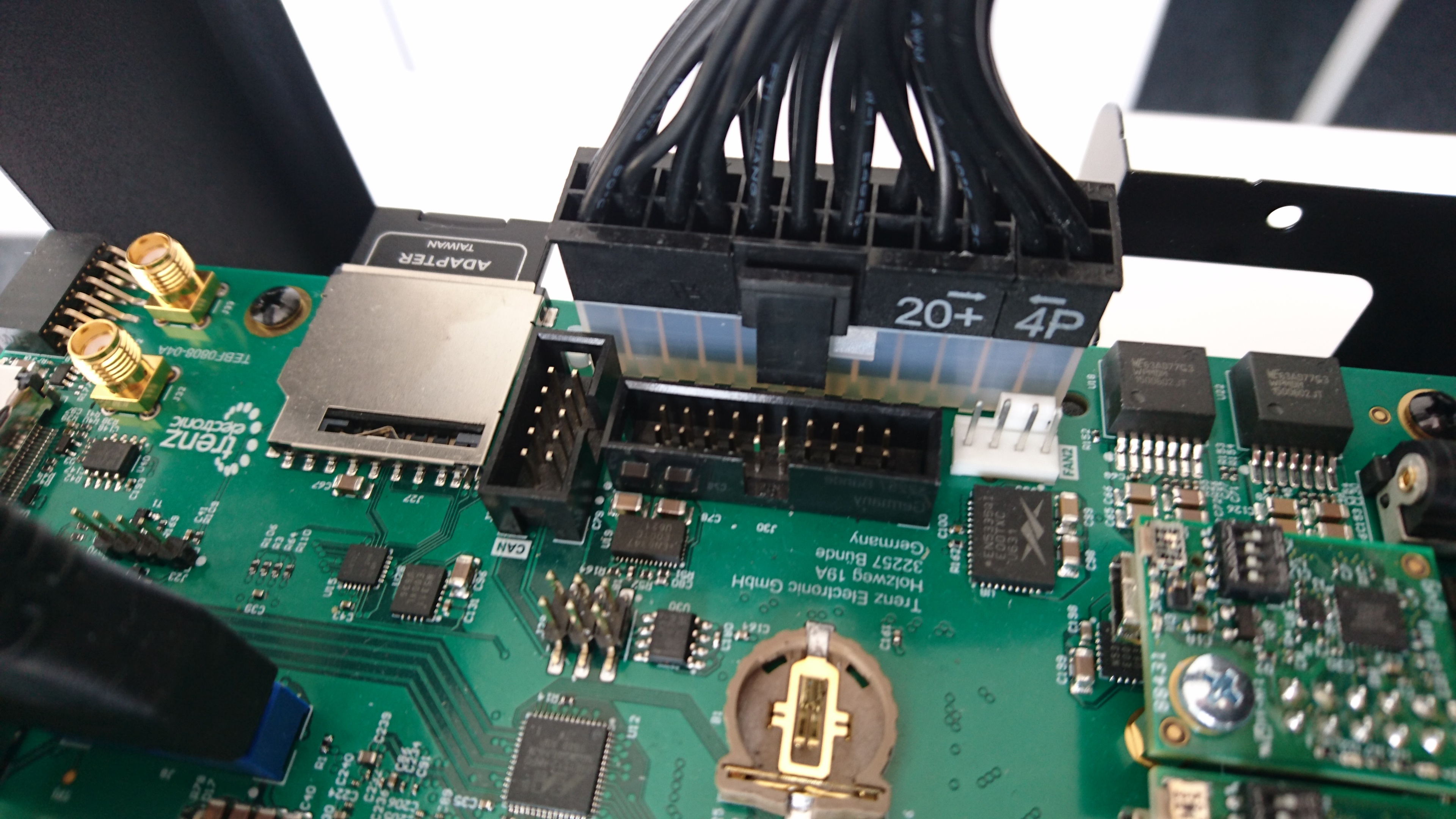
ATX Power
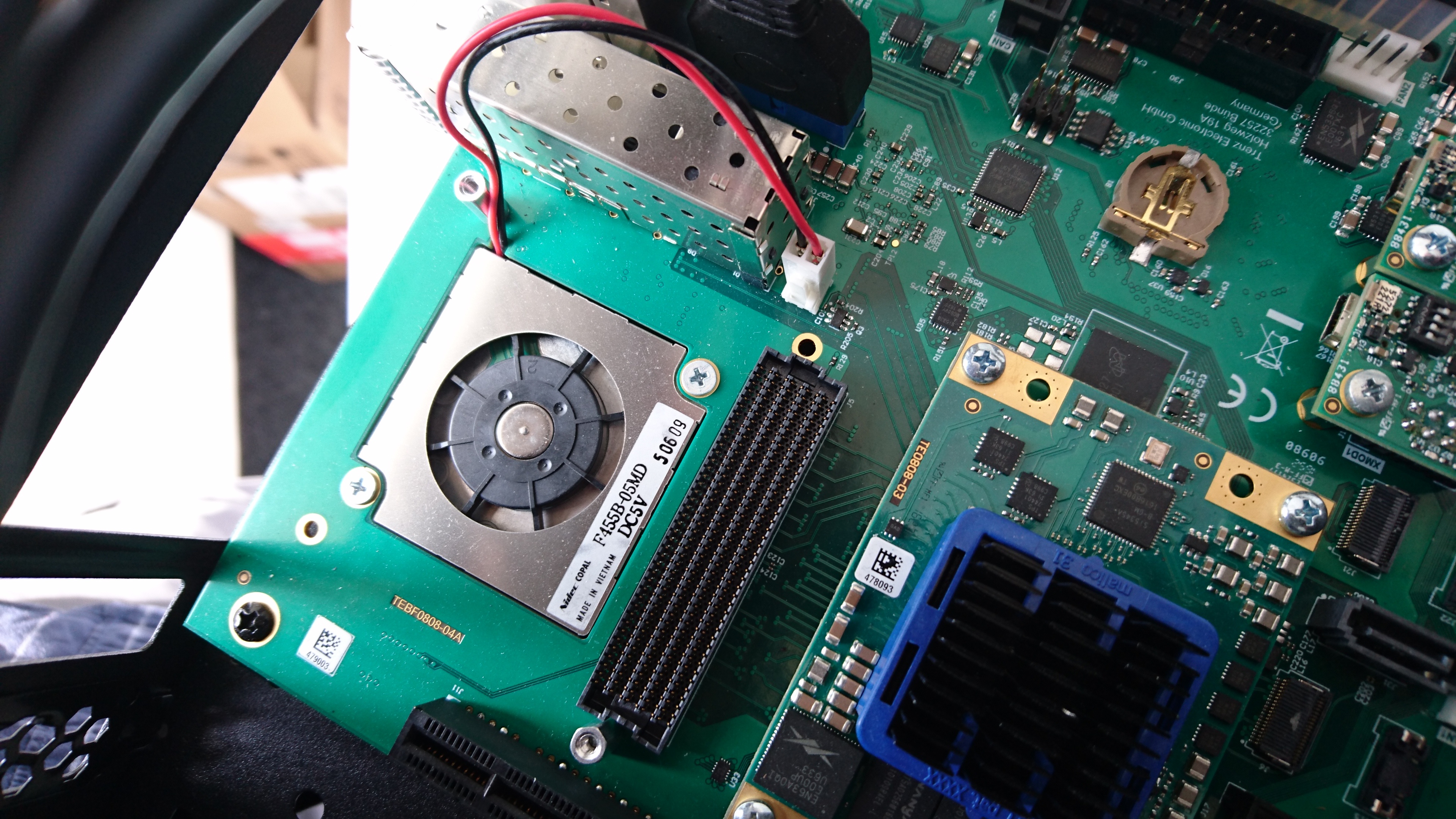
Module
FMC FAN
XMODs

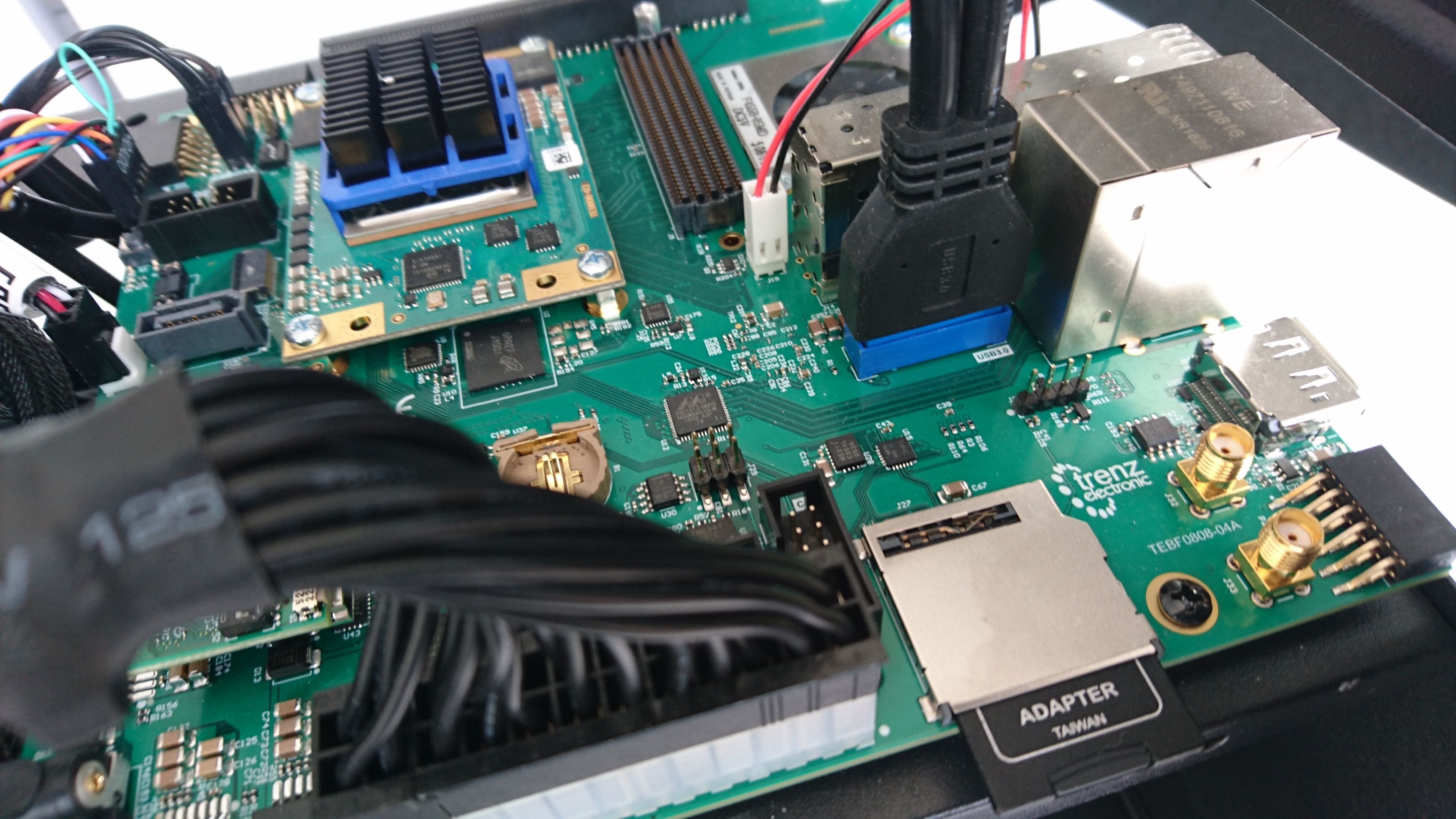
Enclosure USB
Enclosure FAN1 and HDAUDIO
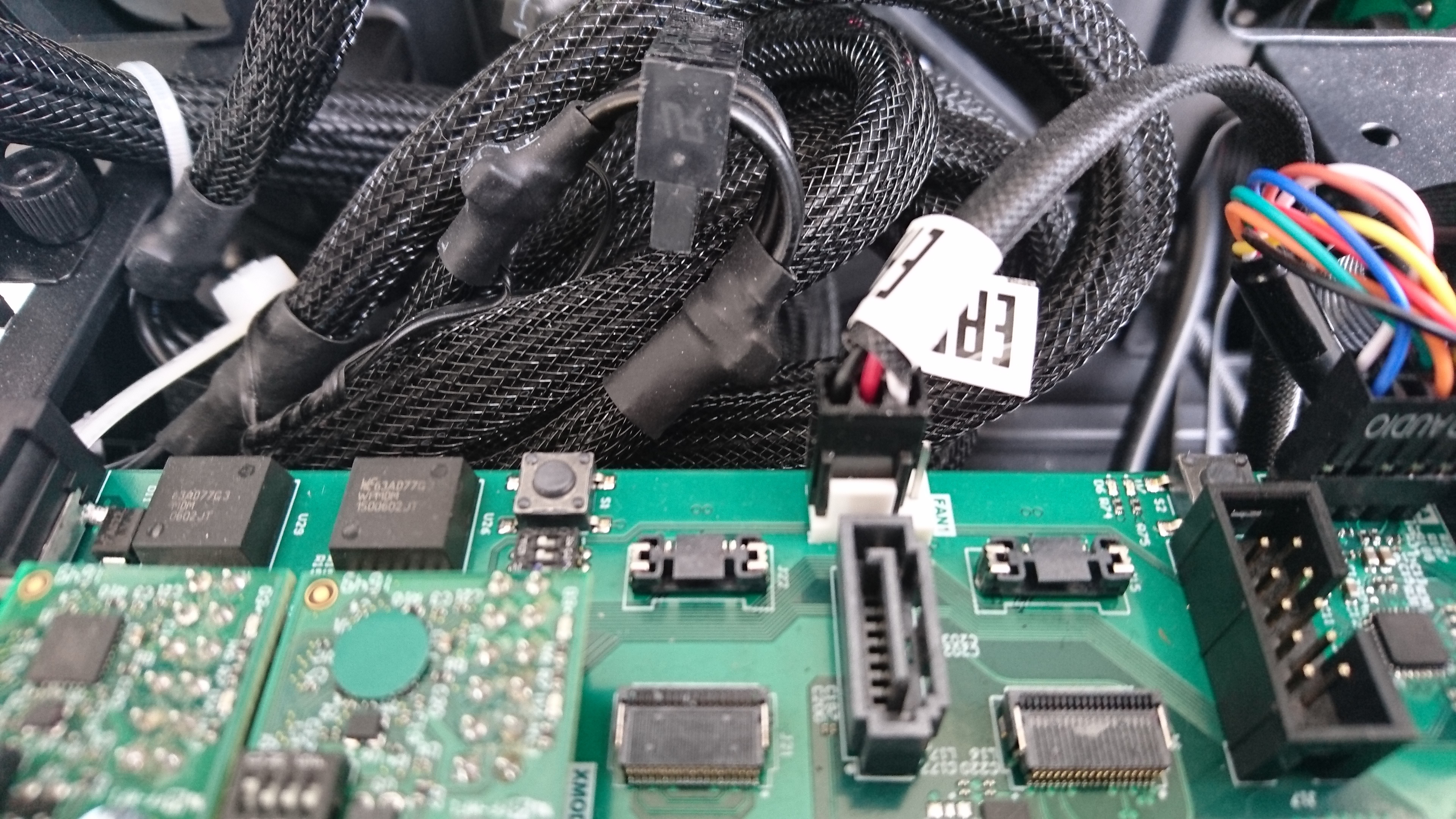
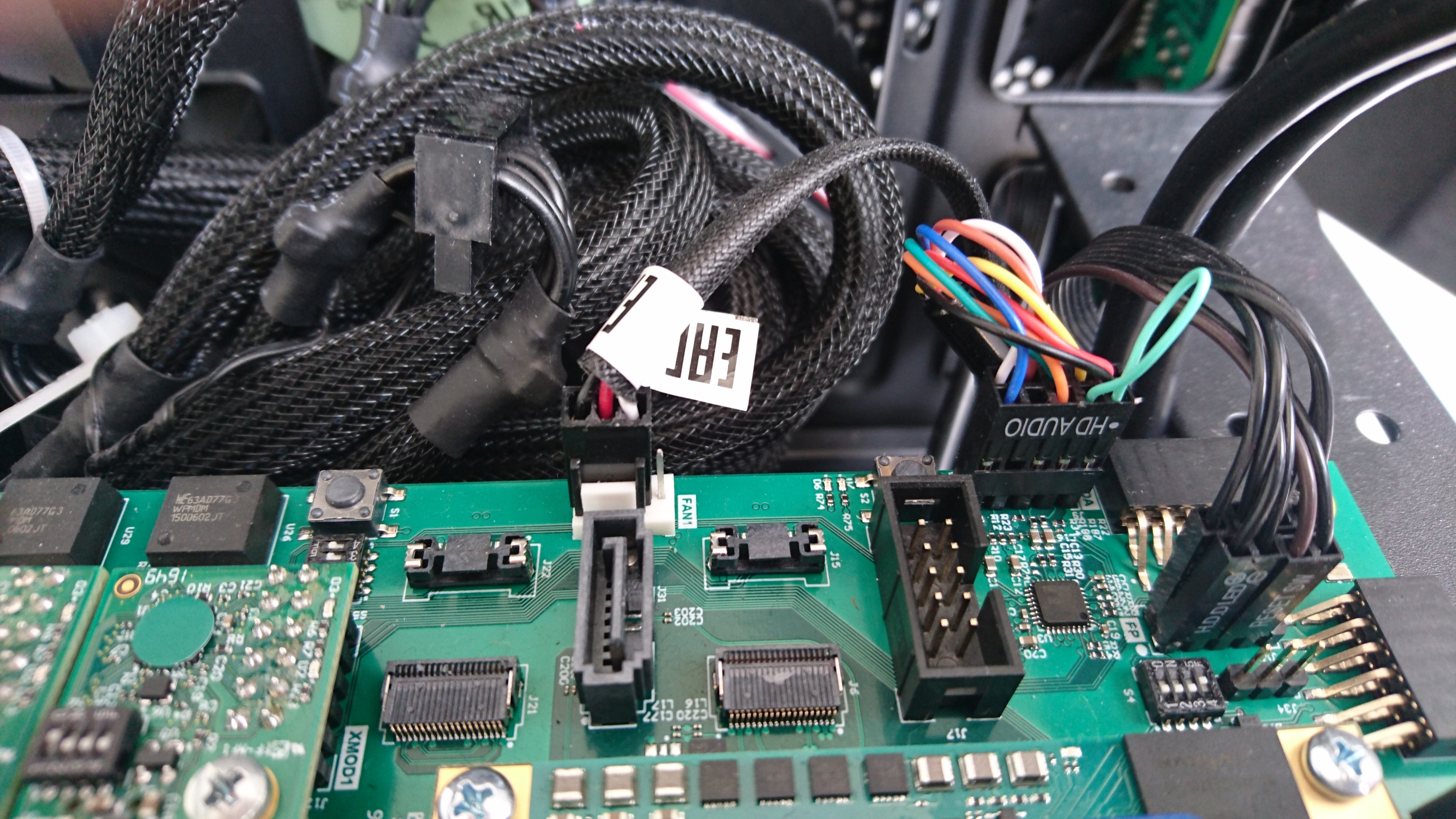
Enclosure Power Button , Reset Button, HDD LED and Power LED
Support
For support, please go to http://forum.trenz-electronic.de/ or contact support@trenz-electronic.de
Overview
Content Tools