Template Revision 2.12
- Module: TRM Name always "TE Series Name" +TRM
Example: "TE0728 TRM" - Carrier: TRM Name usually "TEB Series Name" +TRM
Example: "TEB0728 TRM"
|
<!-- tables have all same width (web max 1200px and pdf full page(640px), flexible width or fix width on menu for single column can be used as before) -->
<style>
.wrapped{
  width: 100% !important;
  max-width: 1200px !important;
 }
</style> |
----------------------------------------------------------------------- |
Note for Download Link of the Scroll ignore macro: |
Table of Contents 
|
Overview
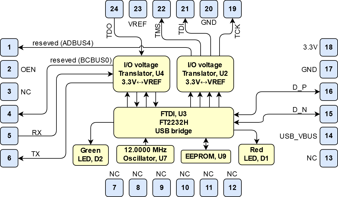
Arrow USB Programmer2 SMD module is a FT2232H based JTAG programmer supported by Intel Quartus. It's designed as Surface-mount module and have to be fitted on the target board in Surface Mount Technology. Furthermore, there is also an UART interface available and two I/O-pins reserved for future use.
Key Features
Note:
'description: Important components and connector or other Features of the module
→ please sort and indicate assembly options Key Features' must be split into 6 main groups for modues: - SoC/FPGA
- Package:
- Speed:
- Temperature:
- RAM/Storage
- On Board
- Interface
- E.g. ETH, USB, B2B, Display port
- Power
- E.g. Input supply voltage
- Dimension
Key Features' must be split into 6 main groups for carrier: - Modules
- TE0808, TE807, TE0803,...
- RAM/Storage
- On Board
- Interface
- E.g. ETH, USB, B2B, Display port
- Power
- E.g. Input supply voltage
- Dimension
|
- Supported by Intel Quartus (JTAG Mode only)
- Designed as Surface-mount module
- Compatible to SMT Pick and Place Assembly Process
- Delivery Option in Standard JEDEC Tray
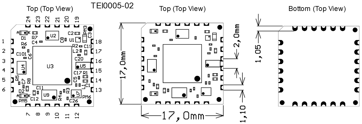
- 17 x 17 mm
- Based on FTDI FT2232H USB2 Interface
- Additional UART channel available
- Activity LEDs
Block Diagram
Signals, Interfaces and Pins
Notes : - For carrier or stand-alone boards use subsection for every connector type (add designator on description, not on the subsection title), for example:
- For modules which needs carrier use only classes and refer to B2B connector if more than one is used, for example
|
Board to Board (B2B)
JTAG module pin assignment.

| Pin | Signal | Module Direction |
|---|
| 1 | reserved for future use | out | | 2 | OEN (enable data transmitting), low active | in | | 3 | Do not connect (reserved for future use) | - | | 4 | reserved for future use | out | | 5 | UART RX | in | | 6 | UART TX | out | | 7...13 | Do not connect (reserved for future use) | - | | 14 | USB-VBUS (USB Host supply voltage) | in | | 15 | USB Data - | bidir | | 16 | USB Data + | | 17 | GND | - | | 18 | 3.3V output voltage from module | out | | 19 | TCK | out | | 20 | GND | - | | 21 | TDI | out | | 22 | TMS | out | | 23 | VREF (Reference I/O-voltage from target board for JTAG and UART) | in | | 24 | TDO | in |
|
USB Interface
The USB interface is provided by the FTDI FT2232H IC. The entire USB protocol is handled on chip and compatible to USB 2.0 High Speed (480 MBps) and Full Speed (12 MBps).
On-board Peripherals
FTDI FT2232H IC
FTDI FT2232H IC (U3) is used in MPSSE Mode for JTAG, Channel B is available as UART. FT2232H EEPROM is programmed with Arrow Programmer2 Identificator to be recognized by the support library for Quartus.
On-board LEDs
On-board LEDs indicating UART and JTAG activity:
| Designator | Color | Connected to | Active Level | Note |
|---|
| D2 | Green | U3-48; U3-49 | low | UART activity (BCBUS3 and BCBUS4) | | D1 | Red | U3-20 | low | JTAG activity (ADBUS7) |
|
Power
Power supply of the adapter board
Arrow Programmer2 is powered via USB_VBUS rail.
Power Distribution Dependencies
Power Rails
| Power Rail Name | Pad
| Direction | Notes |
|---|
| USB_VBUS | 14 | IN |
| | VREF | 23 | IN |
| | 3.3V | 18 | OUT | LDO output generated from USB_VBUS. Do not supply this rail external |
|
Technical Specifications
Absolute Maximum Ratings
| Parameter | Min | Max | Units | Reference Document |
|---|
| USB VBUS | 4.75 | 5.25 | V | USB 2.0 Specification | | VREF | -0.5 | 4.6 | V | Nexperia 74AVCH4T245 data sheet | | Voltage on I/O pins | -0.5 | 4.6 | V | Nexperia 74AVCH4T245 data sheet | | Storage temperature | -55 | +85 | °C | LED LTST-C191KRKT |
|
Recommended Operating Conditions
| Parameter | Min | Max | Units | Reference Document |
|---|
| USB VBUS | 4.75 | 5.25 | V | USB 2.0 Specification | | VREF | 0.8 | 3.6 | V | Nexperia 74AVCH4T245 data sheet (VCCB) | | Voltage on I/O pins | 0 | VREF | V | Nexperia 74AVCH4T245 data sheet | | Operating temperature | -40 | +85 | °C | FTDI FT2232H data sheet |
|
Arrow Programmer2 can be used within industrial temperature range.
Physical Dimensions
Currently Offered Variants
Revision History
Hardware Revision History
| Date | Revision | Changes | Documentation Link |
|---|
| - | 01 | - | TEI0005-01 |
| 2018-05-04 | 02 | - Reconnected D2 for RX TX indication
- Renamed SMD Pads
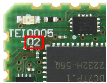
| TEI0005-02 |
Table 5: Hardware revision history.
Hardware revision number can be found on the PCB board together with the module model number separated by the dash.
Document Change History
- Note this list must be only updated, if the document is online on public doc!
- It's semi automatically, so do following
Add new row below first Copy "Page Information Macro(date)" Macro-Preview, Metadata Version number, Author Name and description to the empty row. Important Revision number must be the same as the Wiki document revision number Update Metadata = "Page Information Macro (current-version)" Preview+1 and add Author and change description. --> this point is will be deleted on newer pdf export template - Metadata is only used of compatibility of older exports
|
Date | Revision | Contributors | Description |
|---|
| | | - update all to REV02 and new TRM template >2.0
|
| 2018-01-23 | v.13 | John Hartfiel | - update "Recommended Operating condition"
|
| 2018-01-12 | v.12 | John Hartfiel | - updated physical dimensions
|
| 2017-11-24 | v.11 | Ali Naseri | - updated physical dimensions
|
| v.10 | Ali Naseri | |
Table 6: Document change history.
Disclaimer